EP1344902A2 - Dispositif de commande de soupape à actionnement électromagnétique - Google Patents
Dispositif de commande de soupape à actionnement électromagnétique Download PDFInfo
- Publication number
- EP1344902A2 EP1344902A2 EP03004820A EP03004820A EP1344902A2 EP 1344902 A2 EP1344902 A2 EP 1344902A2 EP 03004820 A EP03004820 A EP 03004820A EP 03004820 A EP03004820 A EP 03004820A EP 1344902 A2 EP1344902 A2 EP 1344902A2
- Authority
- EP
- European Patent Office
- Prior art keywords
- model parameter
- spring
- state
- valve body
- electromagnetically driven
- Prior art date
- Legal status (The legal status is an assumption and is not a legal conclusion. Google has not performed a legal analysis and makes no representation as to the accuracy of the status listed.)
- Withdrawn
Links
- 238000001514 detection method Methods 0.000 claims description 13
- 238000006073 displacement reaction Methods 0.000 description 108
- 230000014509 gene expression Effects 0.000 description 83
- 238000000034 method Methods 0.000 description 80
- 230000008569 process Effects 0.000 description 79
- 230000008859 change Effects 0.000 description 14
- 238000002485 combustion reaction Methods 0.000 description 14
- 230000001133 acceleration Effects 0.000 description 8
- 238000010276 construction Methods 0.000 description 8
- 230000000694 effects Effects 0.000 description 7
- 230000007704 transition Effects 0.000 description 6
- 230000007423 decrease Effects 0.000 description 4
- 238000005516 engineering process Methods 0.000 description 4
- 238000012545 processing Methods 0.000 description 3
- 238000010586 diagram Methods 0.000 description 2
- 230000004044 response Effects 0.000 description 2
- 238000000926 separation method Methods 0.000 description 2
- 238000013459 approach Methods 0.000 description 1
- 238000006243 chemical reaction Methods 0.000 description 1
- 238000004891 communication Methods 0.000 description 1
- 230000006835 compression Effects 0.000 description 1
- 238000007906 compression Methods 0.000 description 1
- 239000013256 coordination polymer Substances 0.000 description 1
- 238000002474 experimental method Methods 0.000 description 1
- 238000003780 insertion Methods 0.000 description 1
- 230000037431 insertion Effects 0.000 description 1
- 239000000314 lubricant Substances 0.000 description 1
- 238000005461 lubrication Methods 0.000 description 1
- 239000000463 material Substances 0.000 description 1
- 238000012986 modification Methods 0.000 description 1
- 230000004048 modification Effects 0.000 description 1
- 230000007935 neutral effect Effects 0.000 description 1
- 230000010355 oscillation Effects 0.000 description 1
- 230000002093 peripheral effect Effects 0.000 description 1
- 230000035699 permeability Effects 0.000 description 1
- 229920000747 poly(lactic acid) Polymers 0.000 description 1
- 238000004549 pulsed laser deposition Methods 0.000 description 1
Images


Classifications
-
- F—MECHANICAL ENGINEERING; LIGHTING; HEATING; WEAPONS; BLASTING
- F01—MACHINES OR ENGINES IN GENERAL; ENGINE PLANTS IN GENERAL; STEAM ENGINES
- F01L—CYCLICALLY OPERATING VALVES FOR MACHINES OR ENGINES
- F01L9/00—Valve-gear or valve arrangements actuated non-mechanically
- F01L9/20—Valve-gear or valve arrangements actuated non-mechanically by electric means
-
- F—MECHANICAL ENGINEERING; LIGHTING; HEATING; WEAPONS; BLASTING
- F16—ENGINEERING ELEMENTS AND UNITS; GENERAL MEASURES FOR PRODUCING AND MAINTAINING EFFECTIVE FUNCTIONING OF MACHINES OR INSTALLATIONS; THERMAL INSULATION IN GENERAL
- F16K—VALVES; TAPS; COCKS; ACTUATING-FLOATS; DEVICES FOR VENTING OR AERATING
- F16K31/00—Actuating devices; Operating means; Releasing devices
- F16K31/02—Actuating devices; Operating means; Releasing devices electric; magnetic
- F16K31/06—Actuating devices; Operating means; Releasing devices electric; magnetic using a magnet, e.g. diaphragm valves, cutting off by means of a liquid
Definitions
- the invention relates to an electromagnetically driven valve control apparatus.
- Control apparatus for electromagnetically driven valves adopted as intake valves or exhaust valves of internal combustion engines have been proposed. See, e.g., Japanese Patent Application Laid-Open Publication Nos. 2001-207875, 2000-234534, 2001-221022, and 2001-221360.
- Such control apparatus perform a position control of a movable element so as to achieve a target operation characteristic, for example, a control of changing the velocity of the movable element, or reducing the velocity of the movable element close to "0" at the time of reaching a seated position, or causing the movable element not to reach a seated position when the internal combustion engine is in a specified operation region, in order to reduce the impact noise produced by the movable element.
- an electromagnetically driven valve is modeled as a spring-mass vibration system in order to achieve a target operation characteristic as mentioned above.
- the value of electric current output to electromagnets in order to achieve a target operation characteristic is adjusted on the basis of a physical model in which the mass of the movable portion, the spring constant and the viscosity coefficient are used as model parameters.
- an electromagnetically driven valve control is executed with the model parameters, that is, the mass of the movable element, the spring constant and the viscosity coefficient, being fixed.
- the electromagnetically driven valve has a movable element that is driven by cooperation of spring force and electromagnetic force, and a valve body that is engageable with the movable element.
- the electromagnetically driven valve performs open-close actions in which the movable element engages with the valve body in accordance with the driving of the movable element. Therefore, there exist periods during which the movable element is moving in a state of disengagement from the valve body, in addition to the periods during which the movable element is moving in a state of engagement with the valve body.
- the electromagnetically driven valve control is executed on the basis of the model with the fixed model parameters, assuming that the valve operates in the engaged state all the time while ignoring the period of operation in the disengaged state. Therefore, during the disengaged state operation period, the spring-mass vibration system model deviates from the actual spring-mass vibration system. For example, after the valve body is seated during movement of the movable element toward the closed valve side, the movable element separates from the valve body, so that the actual mass is only the mass of the movable element, and therefore, the actual spring constant is the spring constant of the spring that urges the movable element. Furthermore, the actual viscosity coefficient becomes the viscosity coefficient related to movement of only the movable element. Due to occurrence of such a deviation of the spring-mass vibration system model, the characteristic of electromagnetic force produced by the electromagnets does not correspond to the target operation characteristic, thus giving rise to a problem of degraded precision of the electromagnetically driven valve control.
- the invention provides an electromagnetically driven valve control apparatus for an electromagnetically driven valve which has a movable element that is driven by cooperation of a spring force and an electromagnetic force, and a valve body engageable with the movable element, and which causes an open-close motion of the valve body due to the movable element engaging with the valve body in accordance with the driving of the movable element.
- the electromagnetically driven valve control apparatus includes: positional information detection means for detecting positional information regarding the movable element; electromagnetic force adjustment means for adjusting an electromagnetic force for driving the movable element so that the movable element reaches a target operation state based on the positional information detected by the positional information detection means and a model of the electromagnetically driven valve obtained as a spring-mass vibration system; and model parameter changing means for determining whether the movable element is operating in a first state in which the movable element is engaged with the valve body or in a second state in which the movable element is disengaged with the valve body based on the positional information detected by the positional information detection means, and for changing a model parameter of the model in the electromagnetic force adjustment means corresponding to the determined state.
- the electromagnetic force adjustment means can use an appropriate model corresponding to changes in the actual spring-mass vibration system. Therefore, the driving of the movable element by the electromagnetic force adjustment means can be performed with high precision, and the precision in the control of the electromagnetically driven valve using a model can be improved.
- positional information is a concept that includes information regarding position, such as changes in position, for example, velocity, acceleration, etc., as well as coordinate position.
- the aforementioned model that includes not only relational expressions that directly express models, but also various relational expressions derived from the aforementioned relational expression, for example, a state observer, an electromagnetic force request value calculating expression derived from the model, etc.
- the movable element in the electromagnetically driven valve, may be urged by a first spring in such a direction as to move the valve body toward an open side, and the valve body may be urged toward a closed side by a second spring.
- the movable element and the valve body are urged by the first spring and the second spring, respectively. Therefore, the model parameters regarding the springs vary depending on whether the movable element and the valve body are engaged. Therefore, since the model parameter changing means changes the model parameter depending on whether the movable element is engaged with the valve body, the electromagnetic force adjustment means can use an appropriate model corresponding to changes in the actual spring-mass vibration system. Therefore, the driving of the movable element by the electromagnetic force adjustment means can be performed with high precision, and the precision in the control of the electromagnetically driven valve using a model can be improved.
- the model parameter changing means may change a model parameter regarding mass corresponding to the determined state.
- the moving mass involved in the movement of the movable element varies depending on whether the movable element is engaged with the valve body. Therefore, the model parameter changing means changes the model parameter regarding mass depending on whether the movable element is engaged with the valve body. Therefore, the electromagnetic force adjustment means can use an appropriate model corresponding to changes in the actual spring-mass vibration system. Hence, the precision in the control of the electromagnetically driven valve using a model can be improved.
- the model parameter changing means may set the model parameter regarding mass based on a total mass of the movable element and the valve body if the determined state is the first state, and the model parameter changing means may change the model parameter regarding mass by setting the model parameter regarding mass based on a mass of the movable element if the determined state is the second state.
- the valve body moves in association with movement of the movable element at the time of engagement between the movable element and the valve body. At the time of disengagement therebetween, the valve body does not move while the movable element moves. Therefore, the difference in mass between the state of engagement and the state of disengagement includes a difference between the total mass of the movable element and the valve body, and the mass of only the movable element. Therefore, the model parameter changing means sets a model parameter based on the total mass of the movable element and the valve body at the time of engagement, and sets a model parameter based on the mass of the movable element at the time of disengagement. Therefore, the electromagnetic force adjustment means can use an appropriate model corresponding to the actual spring-mass vibration system, and the precision in the control of the electromagnetically driven valve using a model can be improved.
- the model parameter changing means may set the model parameter regarding mass based on a total mass of the movable element, the valve body, the first spring and the second spring if the determined state is the first state, and the model parameter changing means may change the model parameter regarding mass by setting the model parameter regarding mass based on a mass of the movable element and the first spring if the determined state is the second state.
- the number of springs that operate varies depending on whether the movable element is engaged with the valve body, a more appropriate difference in mass can be obtained provided that the difference in mass depending on the presence of the engagement of the movable element with the valve body includes a difference between the total mass of the first spring and the second spring and the mass of the first spring alone.
- the model parameter changing means sets a model parameter based on the total mass of the movable element, the valve body, the first spring and the second spring at the time of the engagement, and sets a model parameter based on the mass of the movable element and the first spring at the time of the disengagement.
- the electromagnetic force adjustment means can use an appropriate model corresponding to the actual spring-mass vibration system, and the precision in the control of the electromagnetically driven valve using a model can be improved.
- the model parameter changing means may change a model parameter regarding spring constant corresponding to the determined state.
- the motion of the movable element during the engagement with the valve body involves the first spring urging the movable element and the second spring urging the valve body, and the motion of the movable element during the disengagement from the valve body involves only the first spring urging the movable element. Therefore, since the model parameter changing means changes the model parameter regarding the spring constant depending on whether the movable element is engaged with the valve body, the electromagnetic force adjustment means can use an appropriate model corresponding to the actual spring-mass vibration system, and the precision in the control of the electromagnetically driven valve using a model can be improved.
- the model parameter changing means may set the model parameter regarding spring constant based on a spring constant of a combined spring of the first spring and the second spring if the determined state is the first state, and the model parameter changing means may change the model parameter regarding spring constant by setting the model parameter regarding spring constant based on a spring constant of the first spring if the determined state is the second state.
- the model parameter changing means sets the model parameter regarding spring constant based on the combined spring constant of the first spring and the second spring at the time of the engagement of the movable element with the valve body, and sets the model parameter regarding spring constant based on the spring constant of the first spring alone at the time of the disengagement from the valve body. Therefore, the electromagnetic force adjustment means can use an appropriate model corresponding to the actual spring-mass vibration system, and the precision in the control of the electromagnetically driven valve using a model can be improved.
- the model parameter changing means may change a model parameter regarding spring constant and a model parameter regarding offset of spring corresponding to the determined state.
- the motion of the movable element involves the first spring urging the movable element and the second spring urging the valve body.
- the motion of the movable element involves only the first spring urging the movable element.
- the parameter of offset may also be changed in addition to the parameter of spring constant.
- the electromagnetic force adjustment means can use an appropriate model corresponding to the actual spring-mass vibration system, and the precision in the control of the electromagnetically driven valve using a model can be further improved.
- the model parameter changing means may set the model parameter regarding spring constant and the model parameter regarding offset based on a spring constant of a combined spring of the first spring and the second spring and an offset of the combined spring if the determined state is the first state, and the model parameter changing means may change the model parameter regarding spring constant and the model parameter regarding offset by setting the model parameter regarding spring constant and the model parameter regarding offset based on a spring constant of the first spring and an offset of the first spring if the determined state is the second state.
- the model parameter changing means sets the model parameters regarding spring constant and offset based on the spring constant and the offset of the combined spring of the first spring and the second spring at the time of the engagement of the movable element with the valve body, and sets the model parameters regarding spring constant spring constant and offset based on the spring constant and the offset of the first spring alone at the time of the disengagement from the valve body. Therefore, the electromagnetic force adjustment means can use an appropriate model corresponding to the actual spring-mass vibration system, and the precision in the control of the electromagnetically driven valve using a model can be further improved.
- the model parameter changing means may change a model parameter regarding viscosity coefficient corresponding to the determined state.
- the viscosity coefficient during motion of the movable element varies depending on whether the movable element is engaged with the valve body.
- the resistance generated corresponding to the moving speed changes from the resistance generated at the time of motion of the movable element alone. That is, the viscosity coefficient changes. Therefore, since the model parameter changing means changes the model parameter regarding viscosity coefficient depending on the presence of the engagement of the movable element with the valve body, the electromagnetic force adjustment means can use an appropriate model corresponding to the actual spring-mass vibration system, and the precision in the control of the electromagnetically driven valve using a model can be improved.
- the model parameter changing means may set the model parameter regarding viscosity coefficient based on a total viscosity coefficient of a viscosity coefficient related to motion of the movable element and a viscosity coefficient related to motion of the valve body if the determined state is the first state, and the model parameter changing means may change the model parameter regarding viscosity coefficient by setting the model parameter regarding viscosity coefficient based on the viscosity coefficient related to motion of the movable element if the determined state is the second state.
- the model parameter changing means sets the model parameter based on the viscosity coefficient based on the motion of the movable element and the valve body at the time of engagement therebetween, and sets the model parameter based on the viscosity coefficient based on the motion of the movable element alone at the time of disengagement from the valve body. Therefore, the electromagnetic force adjustment means can use an appropriate model corresponding to the actual spring-mass vibration system, and the precision in the control of the electromagnetically driven valve using a model can be improved.
- the model parameter changing means may change a model parameter regarding a physical quantity that involves a combination of any two, three or four physical quantities selected from the group consisting of mass, spring constant, offset of spring and viscosity coefficient corresponding to the determined state.
- the model parameter changing means changing the parameter regarding the physical quantity that involves a combination of any two, three or four physical quantities selected from the group consisting of mass, spring constant, offset of spring and viscosity coefficient, depending on whether the movable element is engaged with the valve body. Therefore, the electromagnetic force adjustment means can use an appropriate model corresponding to the actual spring-mass vibration system, and the precision in the control of the electromagnetically driven valve using a model can be further improved.
- the model parameter changing means may set the model parameter regarding the physical quantity based on a physical quantity obtained from a combination of the physical quantity regarding the movable element and the physical quantity regarding the valve body if the determined state is the first state, and the model parameter changing means may change the model parameter regarding the physical quantity by setting the model parameter regarding the physical quantity based on the physical quantity regarding the movable element if the determined state is the second state.
- the electromagnetic force adjustment means can use an appropriate model corresponding to the actual spring-mass vibration system, and the precision in the control of the electromagnetically driven valve using a model can be further improved.
- FIG. 1 is a schematic illustration of the construction of an electromagnetically driven valve 2 to which the invention is applied.
- the electromagnetically driven valve 2 is a valve for use as an intake valve or an exhaust valve of an internal combustion engine installed in a vehicle. Since the intake valves and the exhaust valves are identical in a basic construction, the electromagnetically driven valve 2 in FIG. 1 will be described as an intake valve.
- the electromagnetically driven valve 2 has a valve portion 4, an electromagnetic drive portion 6, and a displacement sensor portion 7 (which functions as a positional information detection means).
- the valve portion 4 has a poppet type valve body 8 that is supported on a cylinder head 10 by a valve shaft 8a for to-and-fro movements.
- the cylinder head 10 has an intake port 14 that communicates with a combustion chamber 12. Formed on an opening portion of the intake port 14 on the side of the combustion chamber 12 is a valve seat 16 which the valve body 8 selectively contacts and separates from.
- a lower retainer 18 is provided on an end-side portion of the valve shaft 8a.
- a lower spring 20 (corresponding to a second spring) is disposed in a compressed state between the lower retainer 18 and the cylinder head 10. The whole valve body 8 is urged in a closing direction (upward in FIG. 1) by the lower spring 20.
- the electromagnetic drive portion 6 has an armature 22 (corresponding to a movable element), a lower core 24, and an upper core 26.
- the armature 22, the lower core 24 and the upper core 26 are formed from a high-magnetic permeability material.
- the disc-shape armature 22 has in a central portion thereof an armature shaft 22a that extends through a central hole of the lower core 24 and a central hole of the upper core 26 in such a manner as to allow sliding motion of the shaft.
- the armature shaft 22a, extending through the upper core 26, is fixed to an upper retainer 28.
- An upper spring 30 (corresponding to a first spring) is disposed in a compressed state between the upper retainer 28 and a casing 6a of the electromagnetic drive portion 6.
- the armature shaft 22a is urged toward the valve body 8 (downward in FIG. 1) by the upper spring 30.
- a lower end portion 22b of the armature shaft 22a and an upper end portion 8b of the valve shaft 8a contact each other due to the spring forces of the upper spring 30 and the lower spring 20.
- the armature 22 and the valve body 8 are engaged with each other as indicated in FIG. 1.
- the armature 22 and the valve body 8 are movable together as a single unit.
- the armature shaft 22a and the valve shaft 8a stop at a position of balance between the spring force of the lower spring 20 and the spring force of the upper spring 30.
- the lower spring 20 and the upper spring 30 are identical springs.
- FIG. 1 shows the state of balance.
- the displacement toward the lower core 24 is defined as negative displacement, and the displacement toward the upper core 26 is defined as positive displacement.
- a displacement sensor portion 7 is attached to the casing 6a of the electromagnetic drive portion 6.
- the displacement sensor portion 7 detects the displacement X of the armature 22 by detecting the amount of insertion of the armature shaft 22a extending through the casing 6a and inserted into the displacement sensor portion 7.
- the displacement sensor portion 7 outputs a displacement signal indicating the displacement X, to an electronic control unit (ECU) 32.
- the displacement X of the armature 22 represents the position of the unit of the armature 22 and the valve body 8, within the range of the open side (a lower side in FIG. 1) to a completely closed state (where the valve body 8 contacts the valve seat 16). If the armature 22 further moves from the completely closed state toward the closure side (upward in FIG. 1), the valve body 8 remains seated on the valve seat 16, and undergoes no position change. In such a range, the displacement X represents the position of only the armature 22, which has separated from the valve body 8.
- a lower coil 24a is disposed within the lower core 24.
- An upper coil 26a is disposed within the upper core 26.
- the lower coil 24a and the upper coil 26a are able to induce the lower core 24 and the upper core 26 to generate electromagnetic forces that attract or hold the armature 22, upon magnetizing currents output from the ECU 32.
- a magnetizing current Ilow is supplied to the lower coil 24a so that the lower core 24 attracts the armature 22, the armature 22 moves in such a direction that the valve body 8 moves away from the valve seat 16, overcoming the spring force of the upper spring 30 and the spring force of the lower spring 20.
- the degree of opening of the intake valve increases.
- the degree of opening of the intake valve reaches a maximum when the armature 22 contacts the lower core 24.
- FIG. 2A shows a fully open state.
- the lower end portion 22b of the armature shaft 22a separates from the upper end portion 8b of the valve shaft 8a.
- the spring force of the lower spring 20 does not act on the armature 22, but the armature 22 alone moves upward in the drawings by the electromagnetic force, overcoming the spring force of the upper spring 30.
- the ECU 32 is an electronic circuit formed mainly by a microcomputer.
- the ECU 32 acquires various kinds of information via signals from sensors 34 that include various sensors disposed in the displacement sensor portion 7, the internal combustion engine, etc., and data communications with other ECUs 36 that include an internal combustion engine-purpose ECU, as indicated in FIG. 1.
- the ECU 32 adjusts the magnetizing currents Ilow, Iup supplied to the coils 24a, 26a so as to execute the control of the driving of the electromagnetically driven valve 2.
- the drive control of the electromagnetically driven valve 2 in conjunction with operation of the internal combustion engine is performed by the ECU 32 as exemplified in a timing chart shown in FIG. 3.
- the ECU 32 brings the electromagnetically driven valve 2 from the state shown in FIG. 1 to the open valve state or the closed valve state by repetitively supplying the magnetizing current to the lower coil 24a and the upper coil 26a so as to oscillate the armature 22 and the valve body 8 and gradually increase the amplitude of oscillations thereof.
- the armature 22 Prior to a time point t0 in FIG. 3, the armature 22 is in contact with the lower core 24, and is in a hold state as shown in FIG. 2A. If a valve closure request is output by the other ECU 36, the magnetizing current Ilow supplied to the lower core 24 as a hold current is immediately discontinued (time point t0). Therefore, due to the combined spring force of the lower spring 20 and the upper spring 30, the armature 22 and the valve body 8 start to move together as one unit toward the closed valve side (upward in the drawing).
- valve body 8 becomes seated on the valve seat 16, and therefore completely closed.
- the valve body 8 stops.
- the armature 22 separates from the valve body 8, and moves in the disengaged state until the maximum displacement Xmax is reached.
- the magnetizing current Iup supplied as a hold current to the upper coil 26a is immediately discontinued (time point t4).
- time point t4 to t5 the armature 22 is in the state of disengagement from the valve body 8. Therefore, the armature 22 starts to move toward the open valve side (downward in the drawing) due to the spring force of the upper spring 30 alone.
- the armature 22 After the lower end portion 22b of the armature shaft 22a contacts the upper end portion 8b of the valve shaft 8a (time point t5), the armature 22 is in the state of engagement with the valve body 8, so that the armature 22 and the valve body 8 move together as one unit toward the open valve side (downward in the drawing) due to the spring force of a combined spring of the lower spring 20 and the upper spring 30.
- the ECU 32 is able to control the opening and closing of the intake valve and the degree of opening of the valve to a desired state synchronously with revolution of the internal combustion engine.
- the operation and advantages also can be achieved in the case of an exhaust valve.
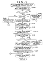
- the process executed by the ECU 32 to supply the magnetizing current to the upper coil 26a at the time of closing the valve is illustrated as an electromagnetically driven valve closure-time control process in FIG. 4.
- the process executed by the ECU 32 to supply the magnetizing current to the lower coil 24a at the time of opening the valve is illustrated as an electromagnetically driven valve opening-time control process in FIG. 5.
- These processes are executed after the startup of the internal combustion engine. The processes are repetitively executed in the cycles of a very short time. Although the processes are illustrated in conjunction with the intake valve, similar electromagnetically driven valve control processes are performed for the exhaust valve.
- the electromagnetically driven valve closure-time control process (FIG. 4) started upon discontinuation of the magnetizing current to the lower coil 24a in response to a valve closing request will be described.
- the present displacement X(i) of the armature 22 is input (S100).
- the displacement X of the armature 22 is constantly calculated by a calculation process that is separately executed on the basis of detection provided by the displacement sensor portion 7. It should be noted herein that the suffix (i) of displacement X indicates the value provided in the present cycle of control.
- the suffix (i-1) indicates the value acquired in the previous cycle of control.
- the suffix (i+1) mentioned below indicates the value acquired in the subsequent cycle of control. That is, X(i-1) represents the displacement X detected in the previous cycle of control. Furthermore, ⁇ t represents the cycle of control of the process.
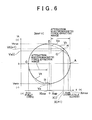
- a target driving velocity Vt corresponding to the displacement X(i+1) of the subsequent cycle of control is set with reference to a map V in which the target driving velocity Vt of the armature 22 is set corresponding to the displacement X (S112).
- the map V is indicated in FIG. 6. This map is stored in a ROM of the ECU 32. As indicated by a solid line in FIG. 6, the target driving velocity Vt for the displacement X of the armature 22 is set in a ring fashion.
- a state A is a state where the valve body 8 is already seated on the valve seat 16, and the electromagnetically driven valve 2 is completely closed, and the armature 22 is held on the upper core 26.
- a state C is a state where the armature 22 is held on the lower core 24, and therefore, the valve body 8 is farthest apart from the valve seat 16, that is, the electromagnetically driven valve 2 is fully open.
- the transition from the state A to the state C occurs via a state B.
- the target driving velocity Vt of the armature 22 is negative velocity (downward movement in FIGS. 1 and 2). In this case, the target driving velocity Vt reaches the least value (a maximum in absolute value) when the armature 22 is at the middle point (state B) between the lower core 24 and the upper core 26.
- the target driving velocity Vt of the armature 22 is positive velocity.
- the target driving velocity Vt reaches the greatest value when the armature 22 is at the middle point (state D) between the lower core 24 and the upper core 26.
- the target driving velocity Vt(i+1) at the displacement X(i+1) in the subsequent cycle of control determined as in the aforementioned expression (2) is indicated as the velocity corresponding to a state H.
- the aforementioned map V is not limited to the arrangement indicated in FIG. 6, but may be suitably set in accordance with the kind of the electromagnetically driven valve 2 and performance requirements thereof.
- the map is arranged as indicated in FIG. 6 as an example, in view of minimizing the energy loss in driving the electromagnetically driven valve 2 through efficient conversion of the elastic energy stored in the lower spring 20 and the upper spring 30 into kinetic energy.
- fa represents the force that mainly acts on the valve body 8 in accordance with the pressure difference between the in-cylinder pressure (pressure in the combustion chamber 12) and the intake pressure on the intake port 14 side, and is set at, for example, a value that is directly proportional to the pressure difference. If the electromagnetically driven valve 2 is an exhaust valve, the pressure difference is a difference between the in-cylinder pressure and the exhaust pressure.
- fb represents the friction resistance on the slide portion of the electromagnetically driven valve 2, and is a constant value set beforehand through experiments or the like. Since the magnitude of friction resistance changes in accordance with the state of lubrication of the sliding site and, in particular, the temperature of lubricant, the value fb may be increased with decreases in the temperature of the internal combustion engine.
- the boundary value Xupb represents the amount of displacement occurring at a boundary regarding whether the lower end portion 22b of the armature shaft 22a contacts the upper end portion 8b of the valve shaft 8a, that is, a boundary regarding whether the armature 22 moves in the state of engagement with the valve body 8 or the state of disengagement from the valve body 8.
- the model parameters in the electromagnetic force request value Fem-calculating expression are a mass parameter m, a viscosity coefficient parameter c, a spring constant k, and an offset amount xofs.
- the mass parameter m is set to a total mass mp of the armature 22, the valve body 8, the lower spring 20 and the upper spring 30.
- the mass of the lower spring 20 and the upper spring 30 is not the net mass, but is the mass of the movable portions thereof, and is therefore less than the actual mass of the springs.
- the viscosity coefficient parameter c is set to a viscosity coefficient cp that occurs when the armature 22 and the valve body 8 move together as one unit.
- the spring constant k is set to the spring constant kp of the combined spring of the lower spring 20 and the upper spring 30.
- the offset amount xofs is "0" when set as a closing-time first model parameter.
- Values of these parameters are empirically determined beforehand, and are stored in the ROM of the ECU 32.
- m ⁇ a represents the force needed to move an object of mass m at the acceleration request value a
- c ⁇ Va(i) represents the force that occurs as a resistance when an object is moved at the actual driving velocity Va(i)
- k ⁇ X(i) represents the spring force that occurs at the displacement X(i).
- k ⁇ xofs represents the spring force that occurs due to offset (offset load), and is “0” in this case.
- an upper attraction current value Iupp to be supplied to the upper coil 26a is calculated (S124).
- the calculation of the upper attraction current value Iupp is performed with reference to an attraction current map that factors in the electromagnetic force request value Fem and the displacement X(i).
- the attraction current map is empirically determined beforehand, and is stored in the ROM of the ECU 32.
- the upper attraction current value Iupp tends to be set greater for greater gaps between the armature 22 and the upper core 26, and also tends to be set greater for greater electromagnetic force request values Fem.
- a magnetizing current Iup for the upper coil 26a is supplied (S126).
- an electromagnetic force request value Fem is calculated using the closing-time first model parameters (S120, S122), and the output of the magnetizing current Iup of the corresponding upper attraction current value Iupp (S124, S126) continues (time point t1 to t2).
- closure-time second model parameters are set as model parameters in the electromagnetic force request value Fem-calculating expression (Expression 5) (S128).
- the mass parameter m is set to the total mass ms of the armature 22 and the upper spring 30.
- the mass of the upper spring 30 is not the net mass thereof, but is the mass of the movable portion of the spring, and is less than the actual mass of the upper spring 30.
- the viscosity coefficient parameter c is set to the viscosity coefficient cs that occurs when the armature 22 moves.
- the spring constant k is set to the spring constant ks of the upper spring 30 alone. It should be noted herein that while X(i) > Xupb, the armature shaft 22a is apart from the valve shaft 8a, and therefore does not receive the spring force of the lower spring 20. Therefore, as a closing-time second model parameter, the offset amount xofs is set to the amount of compression displacement of the upper spring 30 that occurs at the time of a neutral state of the armature 22 as indicated in FIG. 1. These values are empirically determined beforehand, and are stored in the ROM of the ECU 32.
- an electromagnetic force request value Fem is calculated as in the aforementioned expression 5 using these parameters (S122). Since xofs > 0 at this time, "k ⁇ xofs" is not "0".
- an upper attraction current value Iupp to be supplied to the upper coil 26a is calculated (S124).
- a magnetizing current Iup for the upper coil 26a is supplied (S126).
- an electromagnetic force request value Fem is calculated using the closing-time second model parameters (S128, S122), and the output of the magnetizing current Iup of the corresponding upper attraction current value Iupp (S124, S126) continues (time point t2 to t3).
- an upper hold current value Iups is calculated (S130).
- the upper hold current value Iups is a value of current that induces the amount of electromagnetic force that stably holds the armature 22 on the upper core 26, overcoming the spring force that occurs at that time (time point t3 to t4) (in this case, the spring force of the upper spring 30 alone "ks ⁇ X(i) + ks ⁇ xofs"). Then, the upper hold current value Iups is output as a magnetizing current Iup (S126).
- a magnetizing current Ilow for the lower coil 24a is supplied (S224).
- Ilowp "0”
- the magnetizing current Ilow is not supplied (time point t4 to t6).
- the model of the electromagnetically driven valve 2 as a spring-mass vibration system is changed upon contact of the armature shaft 22a with the valve shaft 8a (time point t5).
- this timing time point t5 is within a period during which an attraction control based on the magnetizing current is not performed, a process of changing the model parameters is not performed in the electromagnetically driven valve opening-time control process (FIG. 5).
- opening-time model parameters in the electromagnetic force request value Fem-calculating expression (5) are set (S218). Since the armature 22 is already in the state where the armature 22 and the valve body 8 move together as one unit, the opening-time model parameters are set as mentioned in conjunction with step S120. That is, the mass parameter m is set to the mass mp, and the viscosity coefficient parameter c is set to the viscosity coefficient cp, and the spring constant k is set to the spring constant kp, and the amount of offset xofs is set to "0". That is, the same parameters as the closing-time first model parameters are set.
- an electromagnetic force request value Fem is calculated as in Expression (5) (S220). Then, in order to output the electromagnetic force request value Fem, a lower attraction current value Ilowp to be supplied to the lower coil 24a is calculated (S222). Similar to the upper attraction current value Iupp mentioned in conjunction with step S124, the lower attraction current value Ilowp is determined with reference to an attraction current map that factors in the electromagnetic force request value Fem and the displacement X(i).
- a magnetizing current Ilow for the lower coil 24a is supplied (S224).
- an electromagnetic force request value Fem is calculated using the opening-time model parameters (S218, S220), and the output of the magnetizing current Ilow of the corresponding lower attraction current value Ilowp (S222, S224) continues (time point t6 to t7).
- a lower hold current value Ilows is calculated (S226).
- the lower hold current value Ilows is a value of current that induces the amount of electromagnetic force that stably holds the armature 22 on the lower core 24, overcoming the spring force that occurs at this time (time point t7 and later) (in this case, the spring force "kp ⁇ X(i)" of the lower spring 20 and the upper spring 30).
- the lower attraction current value Ilowp is output as a magnetizing current Ilow (S224).
- the displacement sensor portion 7 functions as a positional information detection means, and steps S118, S120, S128 in the electromagnetically driven valve closing-time control process (FIG. 4) and step S218 in the electromagnetically driven valve opening-time control process (FIG. 5) function as a model parameter changing means. Furthermore, the electromagnetically driven valve closing-time control process (FIG. 4) and the electromagnetically driven valve opening-time control process (FIG. 5) excluding steps S118, S120, S128 and S218 function as an electromagnetic force adjusting means.
- a second embodiment of the invention will next be described.
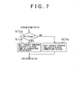
- a process illustrated in FIG. 7 is performed in place of step S112 in the electromagnetically driven valve closing-time control process illustrated in FIG. 4.
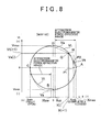
- a map V2 indicated in FIG. 8 is used instead of the map V indicated in FIG. 6.
- the second embodiment is the same as the first embodiment.
- the target driving velocity Vt temporarily becomes "0" (mm/sec) (state P1) when the displacement X equals the boundary value Xupb at which the armature 22 separates from the valve body 8.
- another target driving velocity Vt (> 0) is set (state P2).
- the target driving velocity Vt decreases again as the displacement X(i) increases.
- the target driving velocity Vt becomes "0" (mm/sec).
- the map V2 is the same as the map V (FIG. 6).
- the displacement X(i+1) of the subsequent cycle of control is estimated as in Expression (2) in step S110 (FIG. 4), and then it is determined whether the present displacement X(i) of the armature 22 is less than the boundary value Xupb (S111a in FIG. 7). If X(i) ⁇ Xupb ("YES" at S111a), the armature 22 is in the state of moving the valve body 8. Therefore, a target driving velocity Vt is determined on the basis of the displacement X(i+1) estimated by a portion of the armature-valve body united state (state C-P1) in the map V2 (FIG. 8).
- the target driving velocity Vt is set to a target driving velocity that occurs at the state P1 ("0" in this case).
- the map of the state P2-A may be directly applied if the estimated displacement X(i+1) is within the range (state P2-A) where the armature 22 is moving alone. In this manner, too, the velocity of the unit of the armature 22 and the valve body 8 can be made sufficiently close to "0" before the displacement X(i) reaches the boundary value Xupb.
- an acceleration request value a is calculated as in Expression (3) on the basis of the target driving velocity Vt and the actual driving velocity Va(i) (S114 in FIG. 4). After that, the process as described above in conjunction with the first embodiment is executed (S116 to 126 in FIG. 4).
- the magnetizing current Iup through the upper coil 26a is adjusted so that the unit of the armature 22 and the valve body 8 stops at the boundary value Xupb.
- a target driving velocity Vt (> 0) is set based on a portion of the state P2-A in the map of FIG. 8 (S111c). Then, on the basis of this target driving velocity Vt and the actual driving velocity Va(i), an acceleration request value a is calculated as in Expression (3) (S114 in FIG. 4). After that, the process as described in conjunction with the first embodiment (S116, S118, S128, S122-S126 in FIG. 4) is executed.
- the armature 22 moves toward the upper core 26 at increased actual driving velocity Va(i).
- the magnetizing current Iup of the upper coil 26a is adjusted so that the actual driving velocity Va(i) of the armature 22 becomes "0" at the position of contact of the armature 22 with the upper core 26 (state A).
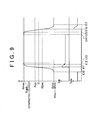
- the armature 22 moves between the lower core 24 and the upper core 26 as indicated in a timing chart shown in FIG. 9. That is, when the supply of the hold current to the lower coil 24a is discontinued (t10), the unit of the armature 22 and the valve body 8 starts moving toward the upper core 26 due to the spring force of the combined spring of the lower spring 20 and the upper spring 30, so that the displacement X increases. Then, when the displacement X exceeds the closing-time passage reference position Xup (t11), the magnetizing current Iup is supplied to the upper coil 26a in accordance with the upper attraction current value Iupp calculated on the basis of the aforementioned closing-time first model parameters.
- the upper attraction current value Iupp is adjusted so as to achieve the target driving velocity Vt indicated between the closing-time passage reference position Xup and the state P1 in the map V2 (FIG. 8). Therefore, control is performed such that the actual driving velocity Va becomes "0" at the position where the displacement X becomes equal to the boundary value Xupb.
- the unit of the armature 22 and the valve body 8 temporarily stops or approximately stops (t12). Exactly at this position, the valve body 8 contacts the valve seat 16. Therefore, the impact of the valve body 8 on the valve seat 16 is reduced, and impact noise can be prevented.
- the target driving velocity Vt becomes positive value again due to adoption of the map of the state P2-A. Therefore, the moving speed of the armature 22 toward the upper core 26 increases. At this time, the armature 22 moves alone in the state of separation from the valve body 8, and therefore, the magnetizing current Iup is supplied to the upper coil 26a in accordance with the upper attraction current value Iupp calculated (S128, S122, S124) on the basis of the aforementioned closing-time second model parameters. Since the upper attraction current value Iupp is adjusted so as to achieve the target driving velocity Vt indicated between the state P2 and the state A in the map V2 (FIG.
- the target driving velocity Vt becomes "0" (state A) at the position where the displacement X reaches the maximum displacement Xmax.
- the armature 22 thus stops (t13). Exactly at this stop position, the armature 22 contacts the upper core 26. Therefore, impact of the armature 22 on the upper core 26 is reduced, and impact noises can be prevented.
- the state where the armature 22 is in contact with the upper core 26 is maintained by the hold current supplied to the upper coil 26a (t13 to t14). Then, when the supply of the hold current to the upper coil 26a is discontinued in order to open the valve, the armature 22 starts to move toward the lower core 24 due to the same process as the electromagnetically driven valve opening-time control process (FIG. 5). During the movement, the armature 22 contacts the valve body 8, and becomes engaged with the valve body 8 (t15), so that the unit of the armature 22 and the valve body 8 moves toward the lower core 24. After that (t16 and later), an attraction current is supplied to the lower coil 24a, so that the armature 22 is attracted toward the lower core 24.
- the velocity of the unit of the armature 22 and the valve body 8 becomes "0".
- the unit of the armature 22 and the valve body 8 thus stops.
- the armature 22 contacts the lower core 24. Therefore, the impact of the armature 22 on the lower core 24 is reduced, and the impact noises can be prevented.
- the target driving velocity Vt of the armature 22 is not brought to "0".
- the reason for this operation is as follows. That is, during the valve-opening drive, the armature 22 contacts the valve body 8 shortly after starting to move. Therefore, the velocity of the armature 22 at the time of contact with the valve body 8 is relatively low, and the noise of impact of the armature 22 on the valve body 8 tends to be low.
- the displacement sensor portion 7 functions as a positional information detection means, and steps S118, S120, S128 in the electromagnetically driven valve closing-time control process (FIGS. 4 and 7) and step S218 in the electromagnetically driven valve opening-time control process (FIG. 5) function as a model parameter changing means. Furthermore, the electromagnetically driven valve closing-time control process (FIGS. 4 and 7) and the electromagnetically driven valve opening-time control process (FIG. 5) excluding steps S118, S120, S128 and S218 function as an electromagnetic force adjusting means.
- a third embodiment of the invention will next be described.
- a negative determination (“NO") is made at step S204 in the electromagnetically driven valve opening-time control process illustrated in FIG. 5
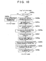
- a process illustrated in FIG. 10 is performed prior to execution of step S206.
- a map for the target driving velocity Vt a map V3 as indicated in FIG. 11 is used.
- the third embodiment is the same as the second embodiment.
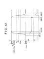
- a timing chart illustrating an example of the control of the third embodiment is shown in FIG. 12.
- the electromagnetically driven valve opening-time control process (FIGS. 5 and 10) will be described below. This process is executed after a time point (t24 in FIG. 12) at which the supply of current to the upper coil 26a is temporarily discontinued due to generation of a valve-opening request. At this time, the armature 22 tends to move apart from the upper core 26 toward the lower core 24 due to the spring force of the upper spring 30. In an initial period of the opening of the valve, the displacement X(i) is greater than the minimum displacement Xmin ("YES" at S202 in FIG. 5), and is also greater than the opening-time passage reference position Xlow ("NO" at S204 in FIG. 5). Therefore, the process illustrated in FIG. 10 is entered.
- This series of steps (S205b to S205j) is the same as the process of the steps S108 to S116, S128, and S122 to S126 where the second model parameters are used in the electromagnetically driven valve closing-time control process (FIG. 4). Therefore, after the armature 22 temporarily moves toward the lower core 24 due to the spring force of the upper spring 30 (t24 and later), the armature 22 stops at the position of the boundary value Xupb (t25) due to the effect of electromagnetic force from the upper core 26, as indicated by the line Lm in FIG. 11. That is, the velocity of the armature 22 becomes "0" when the armature 22 contacts the valve body 8. Therefore, the armature 22 can engage with the valve body 8 without producing impact at the time of contact. After the series of steps (S205b to S205j), the above-described process of steps S206 and S224 is performed, and current is not supplied to the lower coil 24a.
- the process at the time of closing the valve (t20 to t24) is performed as in the above-described electromagnetically driven valve closing-time control process (FIGS. 4 and 7) of the second embodiment.
- the displacement sensor portion 7 functions as a positional information detection means, and steps S118, S120, S128 in the electromagnetically driven valve closing-time control process (FIGS. 4 and 7) and steps S218, S205g (the same as S128) in the electromagnetically driven valve opening-time control process (FIGS. 5 and 10) function as a model parameter changing means.
- the electromagnetically driven valve closing-time control process (FIGS. 4 and 7) and the electromagnetically driven valve opening-time control process (FIGS. 5 and 10) excluding steps S118, S120, S128, S218 and S205g function as an electromagnetic force adjusting means.
- a fourth embodiment of the invention will next be described.
- one of two spring-mass vibration system models designed beforehand by using different model parameters is selected corresponding to a state change between the state of engagement of the armature 22 and the valve body 8 and the state of disengagement thereof.
- This operation changes the model parameters for use in the spring-mass vibration system model and therefore the model itself, between the engaged state and the disengaged state of the armature 22 and the valve body 8.
- the embodiment uses an observer for observing an internal state.
- the observer is formed beforehand.
- the observer is provided for estimating an actual driving velocity Va of the electromagnetically driven valve 2, and for estimating a resultant force of the friction resistance on the sliding portion of the electromagnetically driven valve 2 and the force that acts on the electromagnetically driven valve 2 in accordance with the pressure difference between the in-cylinder pressure and the intake pressure (in the case of an exhaust valve, the difference between the in-cylinder pressure and the exhaust pressure).
- mass mp, viscosity coefficient cp and spring constant kp are values provided when the armature 22 and the valve body 8 move in the engaged state, as described above in conjunction with the first embodiment.
- x represents the amount of displacement of the armature 22
- w represents the external force that acts on the electromagnetically driven valve 2.
- the external force w is the resultant force of the force fa that acts on the electromagnetically driven valve 2 in accordance with the pressure difference between the in-cylinder pressure and the intake pressure (in the case of an exhaust valve, the difference between the in-cylinder pressure and the exhaust pressure) and the friction resistance fb on the sliding portion of the electromagnetically driven valve 2.
- u represents the control input to the model, that is, the electromagnetic force generated by the lower coil 24a and the upper coil 26a.
- a state variable X is defined as in Expression 7.
- first observer An observer for determining an estimated value Z of the state variable X (hereinafter, referred to as "first observer”) is expressed as in Expression (10).
- L is an observer gain
- an estimated value Z can be calculated by the first observer expressed by Expression (10). That is, the external force w and the actual driving velocity Va of the electromagnetically driven valve 2 during the period during which the armature 22 and the valve body 8 move in the engaged state can be estimated. Then, by subtracting the electromagnetic force generated by the coils 24a, 26a from the estimated external force w, the resultant force F based on the aforementioned pressure difference and the friction resistance fb can be estimated.
- the mass ms, the viscosity coefficient cs and the amount of offset xofs are values provided when the armature 22 moves in the state of disengagement from the valve body 8, as mentioned above in conjunction with the first embodiment. Since the offset xofs is constant, the offset load ks ⁇ xofs is also constant. Therefore, if the offset load ks ⁇ xofs is subtracted from the right and left-hand sides of Expression (12), the left-hand side becomes the same as Expression (6). Furthermore, if in the right-hand side, the external force w is assumed to include "-ks ⁇ xofs", and is expressed as wofs, Expression (12) can be rewritten into Expression (13).
- an observer for the case where the armature 22 moves alone (hereinafter, referred to as "second observer") can be designed.
- the second observer the external force wofs and the actual driving velocity Va of the electromagnetically driven valve 2 during the period where the armature 22 moves alone can be estimated.
- the resultant force F of the force fa caused by the differential pressure and the friction resistance fb can be estimated.
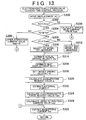
- the electromagnetically driven valve closing-time control process as illustrated in FIG. 13 is executed instead of the electromagnetically driven valve closing-time control process of the first embodiment.
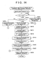
- the electromagnetically driven valve opening-time control process as illustrated in FIG. 14 is executed instead of the electromagnetically driven valve opening-time control process (FIG. 5).
- Steps S300 to S306 and steps S326 to S330 in the electromagnetically driven valve closing-time control process are the same as steps S100 to S106, and S124, S126 and S130 in FIG. 4.
- the control process will be described below mainly with regard to the differences from the process illustrated in FIG. 4.
- the boundary value Xupb represents the amount of displacement that occurs at a boundary regarding whether the armature 22 moves in the state of engagement with the valve body 8 or the state of disengagement from the valve body 8, as mentioned above in conjunction with the first embodiment.
- the first model and the first observer are selected from the two models and the two observers designed as described above (S310). If X(i) ⁇ Xupb is established ("NO" at S308), the second model and the second observer are selected (S312). That is, if X(i) ⁇ Xupb, the first observer and the first model set by the model parameters corresponding to the state where the armature 22 and the valve body 8 are moving together as one unit are selected. Conversely, if X(i) ⁇ Xupb, the second observer and the second model set by the model parameters corresponding to the state where the armature 22 is moving alone are selected.
- the actual driving velocity Va of the armature 22 is estimated as mentioned above (S314).
- the displacement X(i+1) in the subsequent cycle of control is estimated by Expression (2) (S316).
- the target driving velocity Vt corresponding to the displacement X(i+1) in the subsequent cycle of control is set (S318).
- an acceleration request value a is calculated as in Expression (3) (S320).
- the external force F is estimated by the selected observer, as described above (S322).
- An electromagnetic force request value Fem is calculated on the basis of the expression obtained from the selected model (S324). If the first model has been selected, the electromagnetic force request value Fem is calculated on the basis of Expression (14) corresponding to the first model.
- the electromagnetic force request value Fem is calculated on the basis of Expression (15) corresponding to the second model.
- the upper attraction current value Iupp to be supplied to the upper coil 26a is calculated (S326).
- the calculation of the upper attraction current value Iupp is performed with reference to the attraction current map of the electromagnetic force request value Fem and the displacement X(i) as described above in conjunction with the first embodiment.
- the magnetizing current Iup for the upper coil 26a is supplied (S328).
- the upper hold current value Iups is calculated (S330), and the upper hold current value Iups is output as a magnetizing current Iup (S328).
- the upper hold current value Iups is as described above in conjunction with the first embodiment.
- steps S400 to S406, and S422 to S426 are the same as steps S200 to S206, and S222 to S226 in FIG. 5.
- the control process will be described below mainly with regard to the differences from the process illustrated in FIG. 5.
- the first observer and the first model are selected (S408). Therefore, the subsequent estimation of the actual driving velocity Va of the armature 22 is performed by the selected first observer (S410).
- the displacement X(i+1) in the subsequent cycle of control is estimated by Expression (2) (S412).
- the target driving velocity Vt corresponding to the displacement X(i+1) in the subsequent cycle of control is set (S414).
- an acceleration request value a is calculated as in Expression (3) (S416).
- the external force F is estimated by the selected first observer, as described above (S418).
- the electromagnetic force request value Fem is calculated as in Expression (14) corresponding to the first model (S420). After that, the process of steps S422 and S424 is executed.
- the displacement sensor portion 7 functions as a positional information detection means, and steps S308 to S312, and S408 function as a model parameter changing means. Furthermore, the processes of FIGS. 13 and 14 excluding steps S308 to S312, and S408 function as an electromagnetic force adjusting means.
- the above-described fourth embodiment achieves the following advantages.
- the armature 22 is allowed to contact the upper core 26 during the valve-closing drive after the valve body 8 contacts the valve seat 16, it is also possible to prevent the armature 22 from contacting the upper core 26 after separation of the armature 22 from the valve body 8. That is, the electromagnetic force generated by the upper coil 26a may be adjusted so as to stop the armature 22 in a generally termed suspended state where there is a gap between the armature 22 and the upper core 26. In such a suspended control, too, the changing of model parameters and the selection of a model are suitably performed, so that high-precision drive control can be achieved. Hence, impact noise at the time of closure of the valve can be precisely prevented.
- the armature 22 may be stopped in the suspended state with a small gap left between the armature 22 and the lower core 24, by adjusting the electromagnetic force generated by the lower coil 24a.
- This arrangement allows total avoidance of impact of the armature 22 on the lower core 24.
- the changing of model parameters and the selection of a model are suitably performed, so that high-precision drive control can be achieved. Hence, impact noise during the opening of the valve can be precisely prevented.
- the amount of offset of the upper spring 30 is small, or if the amount of offset thereof has only small effect on the control relative to the other parameters, it is also possible to omit the changing of the amount of offset and perform the changing of only the parameters of mass, viscosity coefficient and spring constant.
- the mass of the valve body 8 is considerably small relative to the armature 22, or if the entire mass including the mass of the armature 22 is small so as to have only small effect on the control relative to the other parameters, it is also possible to omit the changing of the parameter of mass and perform the changing of only the parameters of viscosity coefficient, spring constant and offset.
- the viscosity coefficient based on motion of the valve body 8 is considerably small relative to that based on the motion of the armature 22, or if the entire viscosity coefficient including the viscosity coefficient based on the motion of the armature 22 is small so as to have only small effect on the control relative to the other parameters, it is also possible to omit the changing of the parameter of viscosity coefficient and perform the changing of only the parameters of mass, spring constant and offset.
- the spring constant of the lower spring 20 is smaller than that of the upper spring 30, or if the spring constant itself, including the spring constant of the upper spring 30, is small so as to have only small effect on the control relative to the other parameters, it is also possible to omit the changing of the parameter of spring constant and perform the changing of only the parameters of mass, viscosity coefficient and offset. If two of the model parameters of mass, viscosity coefficient, spring constant and offset have particularly great effect on the control, it is also possible to perform the changing with respect to these two model parameters and omit the changing of the other two model parameters. If one of the model parameters of mass, viscosity coefficient, spring constant and offset has particularly great effect on the control, it is also possible to perform the changing with respect to that model parameter and omit the changing of the other three model parameters.
- the mass of the lower spring 20 or the upper spring 30 is smaller than the masses of other movable portions, such as the mass of the armature 22 or the valve body 8, and particularly the mass of the armature 22, it is also possible to reflect only the masses of the armature 22 and the valve body 8 in the parameter of mass.
- a similar arrangement may also be applied to the case of setting an observer that reflects a model of the foregoing fourth embodiment or an expression for calculating an electromagnetic force request value Fem. That is, with regard to all the parameters of mass, viscosity coefficient, spring constant and the offset of spring, suitable one or more of the parameters may be selected in accordance with the engagement or disengagement of the armature 22 and the valve body 8, for use in the setting of a calculating expression for an electromagnetic force request value Fem or an observer. Furthermore, as for the model parameters used for the setting, it is also possible to set only one of the model parameters to as an object of selection, or set only two or three of the model parameters as objects of selection.
- step S120 S128, S218, S205g. That is, in step S120, S218, Expression (14) may be selected for use. In step S128, s205g, Expression (5) may be selected for use.
- the electromagnetically driven valve 2 is used as an intake valve or an exhaust valve of an internal combustion engine, the invention is also applicable to other types of open-close valves.
- a controller (the ECU 32) is implemented as a programmed general purpose computer. It will be appreciated by those skilled in the art that the controller can be implemented using a single special purpose integrated circuit (e.g., ASIC) having a main or central processor section for overall, system-level control, and separate sections dedicated to performing various different specific computations, functions and other processes under control of the central processor section.
- the controller can be a plurality of separate dedicated or programmable integrated or other electronic circuits or devices (e.g., hardwired electronic or logic circuits such as discrete element circuits, or programmable logic devices such as PLDs, PLAs, PALs or the like).
- the controller can be implemented using a suitably programmed general purpose computer, e.g., a microprocessor, microcontroller or other processor device (CPU or MPU), either alone or in conjunction with one or more peripheral (e.g., integrated circuit) data and signal processing devices.
- a suitably programmed general purpose computer e.g., a microprocessor, microcontroller or other processor device (CPU or MPU)
- CPU or MPU processor device
- peripheral e.g., integrated circuit
- a distributed processing architecture can be used for maximum data/signal processing capability and speed.
Landscapes
- Engineering & Computer Science (AREA)
- General Engineering & Computer Science (AREA)
- Mechanical Engineering (AREA)
- Valve Device For Special Equipments (AREA)
- Magnetically Actuated Valves (AREA)
- Output Control And Ontrol Of Special Type Engine (AREA)
Applications Claiming Priority (2)
| Application Number | Priority Date | Filing Date | Title |
|---|---|---|---|
| JP2002065801A JP4055443B2 (ja) | 2002-03-11 | 2002-03-11 | 電磁駆動弁制御装置 |
| JP2002065801 | 2002-03-11 |
Publications (2)
| Publication Number | Publication Date |
|---|---|
| EP1344902A2 true EP1344902A2 (fr) | 2003-09-17 |
| EP1344902A3 EP1344902A3 (fr) | 2007-09-26 |
Family
ID=27764469
Family Applications (1)
| Application Number | Title | Priority Date | Filing Date |
|---|---|---|---|
| EP03004820A Withdrawn EP1344902A3 (fr) | 2002-03-11 | 2003-03-04 | Dispositif de commande de soupape à actionnement électromagnétique |
Country Status (4)
| Country | Link |
|---|---|
| US (1) | US6938591B2 (fr) |
| EP (1) | EP1344902A3 (fr) |
| JP (1) | JP4055443B2 (fr) |
| KR (1) | KR100482528B1 (fr) |
Cited By (1)
| Publication number | Priority date | Publication date | Assignee | Title |
|---|---|---|---|---|
| WO2021105654A1 (fr) * | 2019-11-25 | 2021-06-03 | Camcon Auto Limited | Système de commande de soupape et ses procédés de fonctionnement |
Families Citing this family (9)
| Publication number | Priority date | Publication date | Assignee | Title |
|---|---|---|---|---|
| US7165518B2 (en) * | 2005-02-01 | 2007-01-23 | Ford Global Technologies, Llc | Adjusting valve lash for an engine with electrically actuated valves |
| US7204210B2 (en) * | 2005-02-01 | 2007-04-17 | Ford Global Technologies, Llc | Reducing power consumption and noise of electrically actuated valves |
| JP2007100593A (ja) * | 2005-10-04 | 2007-04-19 | Nissan Motor Co Ltd | 可変動弁機構の制御装置 |
| DE102009004572B4 (de) * | 2009-01-14 | 2010-08-19 | Abb Technology Ag | Verfahren und elektronische Einrichtung zur Kompensation des Driftverhaltens bei einem pneumatischen Stellglied während des Betriebs |
| KR101104789B1 (ko) * | 2009-05-20 | 2012-01-25 | 오종찬 | 급수장치의 재열시스템 |
| JP5644757B2 (ja) * | 2011-12-28 | 2014-12-24 | 株式会社日本自動車部品総合研究所 | 圧力制御装置 |
| GB2504693B (en) * | 2012-08-06 | 2014-12-31 | Camcon Auto Ltd | Valve control systems for internal combustion engines and methods of operation thereof |
| GB202005894D0 (en) * | 2020-04-22 | 2020-06-03 | Wastling Michael | Fast-acting toggling armature uses centring spring |
| CN113859197B (zh) * | 2021-09-26 | 2022-08-30 | 清华大学 | 一种基于阀芯位置预估的电磁阀液压力控制方法和系统 |
Citations (4)
| Publication number | Priority date | Publication date | Assignee | Title |
|---|---|---|---|---|
| JP2000234534A (ja) | 1998-12-17 | 2000-08-29 | Nissan Motor Co Ltd | 電磁駆動弁の制御装置 |
| JP2001207875A (ja) | 2000-01-21 | 2001-08-03 | Nissan Motor Co Ltd | 電磁駆動弁の制御装置 |
| JP2001221360A (ja) | 1999-12-02 | 2001-08-17 | Nissan Motor Co Ltd | 電磁駆動弁の制御装置 |
| JP2001221022A (ja) | 2000-02-04 | 2001-08-17 | Nissan Motor Co Ltd | 電磁駆動弁の制御装置 |
Family Cites Families (10)
| Publication number | Priority date | Publication date | Assignee | Title |
|---|---|---|---|---|
| KR970004292B1 (ko) * | 1993-06-17 | 1997-03-26 | 엘지전자 주식회사 | 브이씨알(vcr)의 수명체크장치 |
| JP3106890B2 (ja) * | 1995-01-11 | 2000-11-06 | トヨタ自動車株式会社 | 内燃機関の弁駆動装置 |
| DE19739840C2 (de) * | 1997-09-11 | 2002-11-28 | Daimler Chrysler Ag | Verfahren zur Steuerung einer elektromagnetisch betätigbaren Stellvorrichtung, insbesondere eines Ventils für Brennkraftmaschinen |
| NO974530L (no) * | 1997-09-30 | 1999-03-31 | Kv Rner Asa | Styreanordning for ventiler av motorer |
| DE19960796C5 (de) * | 1998-12-17 | 2009-09-10 | Nissan Motor Co., Ltd., Yokohama-shi | Elektromagnetisch betätigbare Ventilsteuervorrichtung und Verfahren zum Steuern eines elektromagnetisch betätigbaren Ventils |
| JP2000205442A (ja) * | 1999-01-13 | 2000-07-25 | Nissan Motor Co Ltd | 電磁バルブ駆動制御装置 |
| WO2000071861A1 (fr) * | 1999-05-19 | 2000-11-30 | Fev Motorentechnik Gmbh | Procede de commande d'un mecanisme de distribution electromagnetique pour soupape a gaz a deux voies dans un moteur a combustion interne a piston |
| ATE224505T1 (de) * | 1999-05-27 | 2002-10-15 | Fev Motorentech Gmbh | Verfahren zur endlagenansteuerung eines durch einen elektromagnetischen aktuator betätigten gaswechselventils an einer kolbenbrennkraftmaschine |
| JP3617413B2 (ja) * | 2000-06-02 | 2005-02-02 | 日産自動車株式会社 | 電磁駆動弁の制御装置 |
| JP4281257B2 (ja) * | 2000-06-29 | 2009-06-17 | トヨタ自動車株式会社 | 機関バルブの駆動制御装置 |
-
2002
- 2002-03-11 JP JP2002065801A patent/JP4055443B2/ja not_active Expired - Fee Related
- 2002-10-31 KR KR10-2002-0066774A patent/KR100482528B1/ko not_active Expired - Fee Related
-
2003
- 2003-02-27 US US10/373,812 patent/US6938591B2/en not_active Expired - Fee Related
- 2003-03-04 EP EP03004820A patent/EP1344902A3/fr not_active Withdrawn
Patent Citations (4)
| Publication number | Priority date | Publication date | Assignee | Title |
|---|---|---|---|---|
| JP2000234534A (ja) | 1998-12-17 | 2000-08-29 | Nissan Motor Co Ltd | 電磁駆動弁の制御装置 |
| JP2001221360A (ja) | 1999-12-02 | 2001-08-17 | Nissan Motor Co Ltd | 電磁駆動弁の制御装置 |
| JP2001207875A (ja) | 2000-01-21 | 2001-08-03 | Nissan Motor Co Ltd | 電磁駆動弁の制御装置 |
| JP2001221022A (ja) | 2000-02-04 | 2001-08-17 | Nissan Motor Co Ltd | 電磁駆動弁の制御装置 |
Non-Patent Citations (1)
| Title |
|---|
| SCHERNUS C ET AL: "Modeling of Exhaust Valve Opening in a Camless Engine", SAE TECHNICAL PAPER SERIES, SOCIETY OF AUTOMOTIVE ENGINEERS, WARRENDALE, PA, US, 4 March 2002 (2002-03-04), pages 1 - 15, XP007914450, ISSN: 0148-7191 * |
Cited By (1)
| Publication number | Priority date | Publication date | Assignee | Title |
|---|---|---|---|---|
| WO2021105654A1 (fr) * | 2019-11-25 | 2021-06-03 | Camcon Auto Limited | Système de commande de soupape et ses procédés de fonctionnement |
Also Published As
| Publication number | Publication date |
|---|---|
| EP1344902A3 (fr) | 2007-09-26 |
| KR20030074085A (ko) | 2003-09-19 |
| JP4055443B2 (ja) | 2008-03-05 |
| US20030168029A1 (en) | 2003-09-11 |
| US6938591B2 (en) | 2005-09-06 |
| KR100482528B1 (ko) | 2005-04-14 |
| JP2003269119A (ja) | 2003-09-25 |
Similar Documents
| Publication | Publication Date | Title |
|---|---|---|
| EP1167725B1 (fr) | Dispositif et procédé de commande d'entraínement de soupape | |
| EP1241325B1 (fr) | Appareil et procédé de contrôle d'une soupape électromagnétique | |
| EP1344902A2 (fr) | Dispositif de commande de soupape à actionnement électromagnétique | |
| EP2108789B1 (fr) | Appareil et procédé de contrôle de commande de soupape de moteur | |
| US6373678B1 (en) | Method of regulating the armature impact speed in an electromagnetic actuator by controlling the current supply based on performance characteristics | |
| EP1344903B1 (fr) | Dispositif et procédé pour amortir la fin de course d'un actionneur électromagnétique | |
| EP1106791A2 (fr) | Système électronique de commande pour un actuateur électromagnétique | |
| CN101278106B (zh) | 电磁驱动气门操作机构的控制装置及控制方法 | |
| JP3614092B2 (ja) | 電磁駆動弁のバルブクリアランス推定装置及び制御装置 | |
| EP1308802A2 (fr) | Système de commande par glissement et procédé de commande de mode de glissant | |
| JP4577171B2 (ja) | スライディングモード制御装置 | |
| EP1371820B1 (fr) | Dispositif de commande pour soupapes à actionnement électromagnétique | |
| JP4196571B2 (ja) | 電磁駆動弁の電磁力制御装置 | |
| JP2002054759A (ja) | 電磁駆動弁の制御装置 | |
| JP4706768B2 (ja) | 電磁駆動式動弁機構の制御装置 | |
| JP2001015329A (ja) | 電磁駆動弁のバルブクリアランス推定装置 | |
| JP2016118150A (ja) | 内燃機関の制御装置 |
Legal Events
| Date | Code | Title | Description |
|---|---|---|---|
| PUAI | Public reference made under article 153(3) epc to a published international application that has entered the european phase |
Free format text: ORIGINAL CODE: 0009012 |
|
| 17P | Request for examination filed |
Effective date: 20030403 |
|
| AK | Designated contracting states |
Kind code of ref document: A2 Designated state(s): AT BE BG CH CY CZ DE DK EE ES FI FR GB GR HU IE IT LI LU MC NL PT RO SE SI SK TR |
|
| AX | Request for extension of the european patent |
Extension state: AL LT LV MK |
|
| PUAL | Search report despatched |
Free format text: ORIGINAL CODE: 0009013 |
|
| AK | Designated contracting states |
Kind code of ref document: A3 Designated state(s): AT BE BG CH CY CZ DE DK EE ES FI FR GB GR HU IE IT LI LU MC NL PT RO SE SI SK TR |
|
| AX | Request for extension of the european patent |
Extension state: AL LT LV MK |
|
| 17Q | First examination report despatched |
Effective date: 20080219 |
|
| AKX | Designation fees paid |
Designated state(s): DE FR GB IT |
|
| STAA | Information on the status of an ep patent application or granted ep patent |
Free format text: STATUS: THE APPLICATION IS DEEMED TO BE WITHDRAWN |
|
| 18D | Application deemed to be withdrawn |
Effective date: 20120221 |