EP1344707A2 - Lenkspindel einer Lenksäule für ein Kraftfahrzeug - Google Patents
Lenkspindel einer Lenksäule für ein Kraftfahrzeug Download PDFInfo
- Publication number
- EP1344707A2 EP1344707A2 EP02024230A EP02024230A EP1344707A2 EP 1344707 A2 EP1344707 A2 EP 1344707A2 EP 02024230 A EP02024230 A EP 02024230A EP 02024230 A EP02024230 A EP 02024230A EP 1344707 A2 EP1344707 A2 EP 1344707A2
- Authority
- EP
- European Patent Office
- Prior art keywords
- corrugated tube
- wave
- steering spindle
- spindle according
- wall thickness
- Prior art date
- Legal status (The legal status is an assumption and is not a legal conclusion. Google has not performed a legal analysis and makes no representation as to the accuracy of the status listed.)
- Granted
Links
Images
Classifications
-
- B—PERFORMING OPERATIONS; TRANSPORTING
- B62—LAND VEHICLES FOR TRAVELLING OTHERWISE THAN ON RAILS
- B62D—MOTOR VEHICLES; TRAILERS
- B62D1/00—Steering controls, i.e. means for initiating a change of direction of the vehicle
- B62D1/02—Steering controls, i.e. means for initiating a change of direction of the vehicle vehicle-mounted
- B62D1/16—Steering columns
- B62D1/18—Steering columns yieldable or adjustable, e.g. tiltable
-
- B—PERFORMING OPERATIONS; TRANSPORTING
- B21—MECHANICAL METAL-WORKING WITHOUT ESSENTIALLY REMOVING MATERIAL; PUNCHING METAL
- B21C—MANUFACTURE OF METAL SHEETS, WIRE, RODS, TUBES, PROFILES OR LIKE SEMI-MANUFACTURED PRODUCTS OTHERWISE THAN BY ROLLING; AUXILIARY OPERATIONS USED IN CONNECTION WITH METAL-WORKING WITHOUT ESSENTIALLY REMOVING MATERIAL
- B21C37/00—Manufacture of metal sheets, rods, wire, tubes, profiles or like semi-manufactured products, not otherwise provided for; Manufacture of tubes of special shape
- B21C37/06—Manufacture of metal sheets, rods, wire, tubes, profiles or like semi-manufactured products, not otherwise provided for; Manufacture of tubes of special shape of tubes or metal hoses; Combined procedures for making tubes, e.g. for making multi-wall tubes
- B21C37/15—Making tubes of special shape; Making tube fittings
- B21C37/154—Making multi-wall tubes
-
- B—PERFORMING OPERATIONS; TRANSPORTING
- B21—MECHANICAL METAL-WORKING WITHOUT ESSENTIALLY REMOVING MATERIAL; PUNCHING METAL
- B21C—MANUFACTURE OF METAL SHEETS, WIRE, RODS, TUBES, PROFILES OR LIKE SEMI-MANUFACTURED PRODUCTS OTHERWISE THAN BY ROLLING; AUXILIARY OPERATIONS USED IN CONNECTION WITH METAL-WORKING WITHOUT ESSENTIALLY REMOVING MATERIAL
- B21C37/00—Manufacture of metal sheets, rods, wire, tubes, profiles or like semi-manufactured products, not otherwise provided for; Manufacture of tubes of special shape
- B21C37/06—Manufacture of metal sheets, rods, wire, tubes, profiles or like semi-manufactured products, not otherwise provided for; Manufacture of tubes of special shape of tubes or metal hoses; Combined procedures for making tubes, e.g. for making multi-wall tubes
- B21C37/15—Making tubes of special shape; Making tube fittings
- B21C37/20—Making helical or similar guides in or on tubes without removing material, e.g. by drawing same over mandrels, by pushing same through dies ; Making tubes with angled walls, ribbed tubes or tubes with decorated walls
- B21C37/205—Making helical or similar guides in or on tubes without removing material, e.g. by drawing same over mandrels, by pushing same through dies ; Making tubes with angled walls, ribbed tubes or tubes with decorated walls with annular guides
-
- B—PERFORMING OPERATIONS; TRANSPORTING
- B21—MECHANICAL METAL-WORKING WITHOUT ESSENTIALLY REMOVING MATERIAL; PUNCHING METAL
- B21D—WORKING OR PROCESSING OF SHEET METAL OR METAL TUBES, RODS OR PROFILES WITHOUT ESSENTIALLY REMOVING MATERIAL; PUNCHING METAL
- B21D15/00—Corrugating tubes
- B21D15/04—Corrugating tubes transversely, e.g. helically
- B21D15/06—Corrugating tubes transversely, e.g. helically annularly
-
- B—PERFORMING OPERATIONS; TRANSPORTING
- B62—LAND VEHICLES FOR TRAVELLING OTHERWISE THAN ON RAILS
- B62D—MOTOR VEHICLES; TRAILERS
- B62D1/00—Steering controls, i.e. means for initiating a change of direction of the vehicle
- B62D1/02—Steering controls, i.e. means for initiating a change of direction of the vehicle vehicle-mounted
- B62D1/16—Steering columns
- B62D1/18—Steering columns yieldable or adjustable, e.g. tiltable
- B62D1/19—Steering columns yieldable or adjustable, e.g. tiltable incorporating energy-absorbing arrangements, e.g. by being yieldable or collapsible
- B62D1/192—Yieldable or collapsible columns
Definitions
- the invention relates to a steering shaft of a steering column for a motor vehicle, with at least one section intended for deformation in a crash, wherein at least one such deformable portion formed as a corrugated tube is, at least over part of its longitudinal extent, the at least one the wave crests of the corrugated pipe comprises, is formed multi-layered.
- Steering spindles of steering columns with corrugated pipes as deformable sections are known, for example, from DE 196 31 214 A1, EP 0 709 274 A1, EP 0 872 401 A2 and EP 0 701 070 A1.
- Corrugated tubes as in the event of a crash deformable sections can be used in the steering column in different sections become. It can be used a single corrugated pipe or multiple corrugated pipes in different sections of the steering shaft can be used.
- Deformable sections in the form of corrugated pipes can on the one hand in the event of a crash be compressed in the axial direction, on the other hand, these can be at deflect laterally from a non-axial force.
- DE 2 027 638 A1 further teaches a method for producing a radially corrugated Pipe in which a constant wall thickness or a different Wall thickness and / or profiling of the corrugated tube from shaft to shaft or can be achieved zone by zone. It can thereby be a corrugated tube for a deformable Section of a steering shaft provided with different crumple zones become.
- a corrugated tube of the type mentioned is further from DE 25 44 769 A1 known.
- two-layered Structure of the corrugated tube is the stability with respect to one about the longitudinal axis the corrugated tube acting torque compared to a conventional single-layer construction with a total of the same total thickness of the wall thickness not or only slightly reduced, while a deformation, especially a lateral Buckling at a non-axial force already at a comparatively significantly lower acting force is enabled.
- the object of the invention is to provide a steering spindle of the type mentioned at least one deformable section formed by a corrugated pipe, to provide, with the simultaneous requirements of sufficient stability relative to a torque acting about the longitudinal axis of the corrugated pipe and the loads occurring during normal operation on the one hand and a suitable deformability in the event of a crash on the other hand even better than the previously known facilities can be met. According to the invention succeeds this by a steering shaft with the features of claim 1.
- the flexural rigidity of the corrugated tube in the vicinity of the adjacent Universal joints, where the strongest bending loads occur be improved.
- the "adjacent universal joint" is the one viewed, which the end facing the respective universal joint closer to the corrugated tube.
- the one end of the corrugated tube directly be connected to a universal joint of the universal joint, while the other End of the corrugated tube with a between the corrugated tube and the universal joint lying connecting shaft is connected.
- At least one of Layers of corrugated pipe with a plurality of in the range of wave crests be arranged openings provided. Because the wave crests in the transmission of torques acting about the longitudinal axis of the steering shaft due to their lower distance from the central axis exposed to lower voltages can thereby provide a deformable portion of a steering shaft with a stability that meets the requirements relative to the transmission of torques acting about the longitudinal axis a further improved deformation behavior in the event of a crash, in particular allows easier turning at a non-axially acting force becomes.
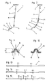
- Figs. 1 and 2 show in highly schematic form two different configurations of steering columns 1.
- a first part 3 of the steering shaft which has a hinged Connection 4 in the form of a universal joint connected to a second part 5 is, which is also called an intermediate wave (possibly a Contains damper).
- the part 5 is connected via an articulated connection 6 with a Steering rod pin 7 of the steering gear in conjunction.
- a hinged connection 26 is connected.
- the articulated connections 6 and 26 are also known as cardan joints executed.
- a steering spindle according to the invention can also be constructed differently, for example, have more or fewer parts 3, 5 and 8.
- At least one of the parts 3, 5 and 8 of the steering shaft is one for deformation arranged in a crash section 9, 10, wherein at least one such deformable portion 9 is formed as a corrugated tube 11.
- deformable sections 9 can also in Shaped sections 10 formed in another shape may be provided, for example in the form of partially telescoped tubes in the event of a crash Axially inserted into each other. Such training of shortenable Sections are known.
- corrugated pipe 11 formed deformable portions 9 may be present in one or more of the Parts 3, 5 and 8 of the steering shaft are arranged.
- FIGS. 3 to 9 an embodiment of a corrugated tube for a steering spindle according to the invention will be briefly explained.
- the corrugated pipe is here over its entire length formed in two layers and used to form the outer layer 14
- Tube 12 has a closed jacket.
- the tube 12 has in shown embodiment thickened ends. In the area between these thickened Ends the wall thickness of the tube is lower contrast.
- this middle portion of the tube is in Fig. 3 as well as in Figs. 5 to 7, 10 and 11 no change in the wall thickness recognizable (for the sake of clarity in this Not shown). However, such is present and in Figs. 13 to 15 shown oversubscribed. These FIGS. 13 to 15 will be explained in more detail below.
- the inner layer 15 forming tube 13 has This embodiment, a plurality of openings 16.
- the tube 13 is in each case with several in the circumferential direction provided spaced apart openings 16, for example can each be seven equally spaced along a circumferential line 17 spaced in this embodiment, circular openings 16 are arranged be.
- the tube 12 is fitted to the tube 13, as shown in Fig. 5. through an expanding mandrel, the inner tube 13 can be widened in sequence to the two layers 14, 15 close together.
- the corrugations are formed, for example by a multi-stage process, as indicated by FIGS. 6 and 7.
- a method can be used, as in the introduction to the description EP 0782 891 B1. This will be first the pipe wall from the outside and inside against the pipe wall pressed molds having corrugations provided with a corrugation, being several such molds with an increasingly strong corrugation can be used. Furthermore, this is preformed according to FIG. 6 Tube pushed together in the axial direction, the tube of is supported inside with a mandrel and from the outside cheek plates in the individual Troughs are retracted, which are pushed towards each other in the axial direction become.
- two-layer corrugated tube accordingly 7 are in the region of the wave peaks 18 in the inner layer 15 a plurality arranged by openings 16.
- all Wave crests with a plurality of circumferentially spaced apart openings 16 provided.
- the troughs 19 are conveniently at least until to a quarter of the height H between the troughs 19 and the wave crests 18 free of openings 16 (see Fig. 9).
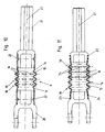
- the corrugated pipe 11 can be installed in a part 3, 5, 8 of the steering shaft become.
- a connection with a link fork 20 and on the other side a connection with a shaft 21 shown.
- this is positively by means Nopponne 22 formed, which in corresponding recesses in the joint fork 20 and 21 intervene.
- Nopponne 22 are the two layers 14, 15 of the corrugated pipe also against a mutual displacement secured in the circumferential direction.
- Noppungen could also other positive connections, in particular press connections, provided be, for example, gears.
- the corrugated tube 11 with the joint fork 20 and the shaft 21 via welds 23rd and / or welds 24 connected together. These welds 23 and 24 can simultaneously connect between the two layers 14, 15 produce. Laser or ultrasonic welding 23, both layers 14, 15 enforce and reach to the joint fork 20 or shaft 21, can be provided for security reasons.
- the corrugated tube 11 could also be integrally formed with a subsequent part of the steering shaft.
- Wave peaks 18 of the inner layer 15 is provided with openings 16, wherein the with Openings 16 provided wave crests 18 in a portion of the longitudinal extent lie of the corrugated pipe.
- the two wave peaks 18, on the neighboring Cardan joint 6, 26 facing side of the corrugated tube 11 are on the other hand free from such openings, as in this area in the ordinary Operation of the steering spindle, the largest of the adjacent universal joint originating non-axial forces occur in the form of bending loads.
- openings 24 are indicated in Fig. 11 by dashed lines. It is advantageous here when the openings 24 are offset from the openings 16 so that the openings 24 from the inner layer 15 to the interior of the corrugated tube 11 out are closed.
- the openings in the trough and the openings are dimensioned in the wave mountain so that the weakening by in the area the troughs attached openings is less than the weakening by the openings 16, 24 in the region of the wave crests.
- corrugated pipes according to the invention could also be used without such openings 16, 24 be formed.
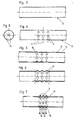
- the portion of the tube 12 in which the corrugations are formed is two Sections with different wall thicknesses D1 and D2, which are stepped connect to each other.
- the section with the larger wall thickness D1 is located doing so on the adjacent universal joint 6 and 26 facing side.
- the wave crests 18 and troughs 19, in the section with the wall thickness D1 be formed therefore, have a greater wall thickness, as the wave crests and troughs, which are formed in the section with the wall thickness D2. If this training is a method is used, during which the formation of the corrugations in the troughs the wall thickness is increased in relation to the wave crests (see that in the introduction to the description above-mentioned EP 0782 891 B1) these different wall thickness changes.
- FIG. 14 are in the area in which the corrugations be formed, three sections with different wall thicknesses D1, D2, D3 provided, which connect stepwise to each other, taking the wall thickness D2 is greater than the wall thickness D3 and the wall thickness D1 is greater than that Wall thickness D2 and in the finished state of the steering shaft the adjacent Cardan joint 6, 26 on the side of the section with the wall thickness D1 of Tube 12 connects to the finished corrugated tube.
- FIG. Another embodiment is shown in FIG. Here are the places where the crests of the wave crests are formed indicated by the arrow 18. Between these wave mountains wave troughs are formed, wherein on the in the finished state of the corrugated pipe or the steering shaft the adjacent Universal joint 6, 26 facing side of the tube 12, the tube 12 in Area of these troughs is provided with wall thickness thickening.
- the first this wall thickness thickening has the strength S1 and the next one in contrast slightly reduced S2 strength.
- the tube 12 has a wall thickness of thickness S3.
- the closest to the adjacent Cardan joint 6, 26 lying wave trough has the largest wall thickness. Also, by the wall thickness thickening S1, S2, the wall thickness of the associated Weller valleys increased compared to the neighboring wave mountains.
- the inner Tube 13 be provided with changes in wall thickness of the type described, so that in the finished state of the corrugated tube such wall thickness changes only or in the inner layer.
- an embodiment of the two or more layers 14, 15 of the corrugated tube 11 from different materials is conceivable and possible. So could the outer one Layer 14 act as a heat shield and between the outer layer 14 and the from a comparatively cheaper material existing inner Layer 15 is a spacer material, for example in the form of a metal mesh or wire grid 25 may be provided, as shown schematically in Fig. 12 is. Also, an additional outer layer could be provided as corrosion protection be, e.g. a comparatively thin layer of stainless steel. All too Layers of the corrugated tube could consist of stainless steel (stainless steel or stainless steel).
- the multi-layered design of the corrugated pipe could also only one Extend part of its longitudinal extent, for example, over the corrugated part its longitudinal extent. At least the corrugated pipe is over part of it Longitudinal extent, the at least one of the wave crests and preferably also one of the troughs of the corrugated pipe comprises multilayered. Even though A two-tiered training is considered beneficial would be fundamental Also a three- or multi-layered training conceivable and possible. at a three-layered training could be the wall thicknesses of the individual layers for example, in the range of about 0.4mm.
- the height H of the corrugation could also change, whereby the distance of the corrugation Wellentals from the longitudinal axis 27 of the corrugated pipe of one or more of the adjacent universal joint 6, 26 adjacent troughs is greater than the one from this universal joint 6, 26 more distant troughs.
- the corrugated tube is characterized in the vicinity of the adjacent universal joint 6, 26, where the strongest bending stresses occur, more rigid, with the height H the curl in this area is lower.
- the steering shaft in improved On the one hand to the loads occurring during normal operation on the other hand adapted to the requirements for the crash case.
Landscapes
- Engineering & Computer Science (AREA)
- Mechanical Engineering (AREA)
- Chemical & Material Sciences (AREA)
- Combustion & Propulsion (AREA)
- Transportation (AREA)
- Vibration Dampers (AREA)
- Steering Controls (AREA)
Abstract
Description
- die Fig. 1 und 2
- stark schematisierte Darstellungen von möglichen Ausbildungen von Lenksäulen;
- die Fig. 3 bis 7
- Längsmittelschnitte von verschiedenen Herstellungsschritten bei der Herstellung eines Wellrohres;
- Fig. 8
- einen Querschnitt des Rohres von Fig. 4;
- Fig. 9
- einen vergrößerten Ausschnitt von Fig. 7;
- Fig. 10
- einen Längsmittelschnitt durch einen Teil der Lenkspindel, die einen deformierbaren Abschnitt in Form eines Wellrohres enthält;
- Fig. 11
- eine Fig. 10 entsprechende Abbildung eines weiteren Ausführungsbeispiels der Erfindung;
- Fig. 12
- eine Fig. 9 entsprechende vergrößerte Teilansicht eines Wellbalges gemäß einem weiteren Ausführungsbeispiel der Erfindung und
- die Fig. 13, 14 und 15
- schematische Darstellungen von Längsmittelschnitten einer Wandung eines Rohres mit Bereichen unterschiedlicher Wandstärke.
- 1
- Lenksäule
- 2
- Lenkrad
- 3
- Teil der Lenkspindel
- 4
- gelenkige Verbindung
- 5
- Teil der Lenkspindel
- 6
- gelenkige Verbindung
- 7
- Lenkstockzapfen
- 8
- Teil der Lenkspindel
- 9
- deformierbarer Abschnitt
- 10
- zusammenschiebbarer Abschnitt
- 11
- Wellrohr
- 12
- Rohr
- 13
- Rohr
- 14
- äußere Schicht
- 15
- innere Schicht
- 16
- Öffnung
- 17
- Umfangslinie
- 18
- Wellenberg
- 19
- Wellental
- 20
- Gelenkskabel
- 21
- Welle
- 22
- Nocken
- 23
- Verschweißung
- 24
- Öffnung
- 25
- Drahtgitter
- 26
- gelenkige Verbindung
- 27
- Längsachse
Claims (16)
- Lenkspindel einer Lenksäule (1) für ein Kraftfahrzeug, mit mindestens einem zur Deformation bei einem Crash vorgesehenen Abschnitt (9, 10), wobei mindestens ein solcher deformierbarer Abschnitt (9) als Wellrohr (11) ausgebildet ist, das zumindest über einen Teil seiner Längserstreckung, der zumindest einen der Wellenberge (18) des Wellrohres (11) umfaßt, mehrschichtig ausgebildet ist, dadurch gekennzeichnet, daß die in einem jeweiligen Wellental (19) des Wellrohres (11) und/oder die in einem jeweiligen Wellenberg (18) des Wellrohres (11) vorliegende Wandstärke von zumindest einer der Schichten (14, 15) sich über den Bereich der Wellenberge (18) bzw. Wellentäler (19) zwischen der dem benachbarten Kardangelenk (6, 26) zugewandten Seite und der dem benachbarten Kardangelenk (6,26) abgewandten Seite des Wellrohres (11) verringert.
- Lenkspindel nach Anspruch 1, dadurch gekennzeichnet, daß sich die Wandstärke zumindest über einen Teil des Bereichs der Wellenberge (18) und Wellentäler (19) kontinuierlich zwischen einem Wellental (19) und dem nächsten bzw. zwischen einem Wellenberg (18) und dem nächsten verringert.
- Lenkspindel nach Anspruch 1, dadurch gekennzeichnet, daß sich die in den Wellentäler (19) und/oder Wellenbergen (18) vorliegende Wandstärke stufenförmig ändert, wobei vorzugsweise eine oder zwei solche Stufen vorgesehen sind.
- Lenkspindel nach einem der Ansprüche 1 bis 3, dadurch gekennzeichnet, daß die Wandstärke von zumindest einer der Schichten (14, 15) zumindest im Bereich eines Wellenberges (18) geringer ist als im benachbarten Wellental (19), vorzugsweise um zumindest 20 %.
- Lenkspindel nach Anspruch 4, dadurch gekennzeichnet, daß die Wandstärke von zumindest einer der Schichten (14, 15) jedes Wellenberges (18) geringer ist als in einem benachbarten Wellental (19), vorzugsweise um zumindest 10%.
- Lenkspindel nach einem der Ansprüche 1 bis 5, dadurch gekennzeichnet, daß das Wellrohr (11) zumindest über den Teil seiner Längserstreckung, in welchem die Wellenberge (18) und Wellentäler (19) angeordnet sind, vorzugsweise über seine gesamte Länge, mehrschichtig ausgebildet ist.
- Lenkspindel nach Ansprüche 1 bis 6, dadurch gekennzeichnet, daß zumindest eine der Schichten (14, 15) des Wellrohres (11) mit einer Mehrzahl von im Bereich von Wellenbergen (18) angeordneten Öffnungen (16, 24) versehen ist.
- Lenkspindel nach Anspruch 7, dadurch gekennzeichnet, daß zumindest ein Wellenberg (18), vorzugsweise mehrere Wellenberge (18), mit mehreren in Umfangsrichtung des Wellrohres (11) voneinander beabstandeten Öffnungen (16, 24) versehen ist/sind.
- Lenkspindel nach Anspruch 7 oder Anspruch 8, dadurch gekennzeichnet, daß zumindest der an das einem benachbarten Kardangelenk (6, 26) zugewandte Ende des Wellrohres (11) anschließende Wellenberg (18) für alle Schichten (14, 15) des Wellrohres (11) frei von Öffnungen (16, 24) ist, vorzugsweise mehrere an dieses Ende des Wellrohres (11) anschließende Wellenberge (18) frei von Öffnungen (16, 24) sind.
- Lenkspindel nach einem der Ansprüche 7 bis 9, dadurch gekennzeichnet, daß die Wellentäler (19) zumindest bis zu einem Viertel der Höhe (H) zwischen Wellental (19) und Wellenberg (18) frei von Öffnungen (16, 24) sind.
- Lenkspindel nach einem der Ansprüche 1 bis 10, dadurch gekennzeichnet, daß die Schichten (14, 15) aus verschiedenen Materialien bestehen.
- Lenkspindel nach Anspruch 11, dadurch gekennzeichnet, daß die äußere Schicht aus einem korrosionsbeständigen Material besteht, vorzugsweise Edelstahl, oder korrosionsfest beschichtet ist.
- Lenkspindel nach Anspruch 11 oder Anspruch 12, dadurch gekennzeichnet, dass die äußere Schicht aus einem hitzebeständigen Material besteht.
- Lenkspindel nach einem der Ansprüche 1 bis 13, dadurch gekennzeichnet, daß zwischen zwei Schichten (14, 15) ein Distanzmaterial, vorzugsweise Metallgeflecht oder Drahtgitter (25), zumindest über einen Teil der Länge des Wellrohres angeordnet ist.
- Lenkspindel nach einem der Ansprüche 1 bis 14, dadurch gekennzeichnet, daß sich die Höhe (H) der Wellung über den gewellten Bereich ändert, wobei der Abstand des Wellentals von der Längsachse (27) des Wellrohrs von einem oder mehreren dem benachbarten Kardangelenk (6, 26) benachbarten Wellentäler größer ist als derjenige von von diesem Kardangelenk (6, 26) weiter entfernt liegenden Wellentälern.
- Verfahren zur Herstellung einer Lenksäule nach einem der Ansprüche 1 bis 15, dadurch gekennzeichnet, daß das Wellrohr (11) durch Einbringen einer Wellung in mindestens zwei vor dem Einbringen der Wellung ineinander geschobene Rohre (12, 13) ausgebildet wird, wobei mindestens eines der Rohre (12, 13) vor dem Einbringen der Wellung in dem für das Einbringen der Wellung vorgesehenen Bereich mit einer Änderung seiner Wandstärke versehen wird.
Priority Applications (1)
| Application Number | Priority Date | Filing Date | Title |
|---|---|---|---|
| US10/388,010 US6896290B2 (en) | 2002-03-14 | 2003-03-13 | Steering gear shaft for a steering column of a motor vehicle |
Applications Claiming Priority (2)
| Application Number | Priority Date | Filing Date | Title |
|---|---|---|---|
| DE2002111743 DE10211743A1 (de) | 2002-03-14 | 2002-03-14 | Lenkspindel einer Lenksäule für ein Kraftfahrzeug |
| DE10211743 | 2002-03-14 |
Publications (3)
| Publication Number | Publication Date |
|---|---|
| EP1344707A2 true EP1344707A2 (de) | 2003-09-17 |
| EP1344707A3 EP1344707A3 (de) | 2003-10-22 |
| EP1344707B1 EP1344707B1 (de) | 2006-05-24 |
Family
ID=27762955
Family Applications (2)
| Application Number | Title | Priority Date | Filing Date |
|---|---|---|---|
| EP20020024230 Expired - Lifetime EP1344707B1 (de) | 2002-03-14 | 2002-10-31 | Lenkspindel einer Lenksäule für ein Kraftfahrzeug |
| EP20020024231 Expired - Lifetime EP1344708B1 (de) | 2002-03-14 | 2002-10-31 | Lenkspindel einer Lenksäule für ein Kraftfahrzeug |
Family Applications After (1)
| Application Number | Title | Priority Date | Filing Date |
|---|---|---|---|
| EP20020024231 Expired - Lifetime EP1344708B1 (de) | 2002-03-14 | 2002-10-31 | Lenkspindel einer Lenksäule für ein Kraftfahrzeug |
Country Status (3)
| Country | Link |
|---|---|
| EP (2) | EP1344707B1 (de) |
| DE (3) | DE10211743A1 (de) |
| ES (2) | ES2264714T3 (de) |
Cited By (1)
| Publication number | Priority date | Publication date | Assignee | Title |
|---|---|---|---|---|
| CN111872187A (zh) * | 2020-06-30 | 2020-11-03 | 韩阳 | 一种波纹管的成型系统 |
Families Citing this family (2)
| Publication number | Priority date | Publication date | Assignee | Title |
|---|---|---|---|---|
| DE102006005736A1 (de) | 2006-02-07 | 2007-08-09 | Thyssenkrupp Presta Ag | Wellrohr |
| JP5120601B2 (ja) | 2007-04-27 | 2013-01-16 | 株式会社ジェイテクト | 衝撃吸収ステアリング装置 |
Citations (10)
| Publication number | Priority date | Publication date | Assignee | Title |
|---|---|---|---|---|
| CH324476A (fr) | 1954-08-06 | 1957-09-30 | Napier & Son Ltd | Procédé de fabrication d'un soufflet métallique |
| DE2027638A1 (de) | 1970-06-05 | 1971-12-16 | Reiche & Co | Verfahren und Vorrichtung zum Herstellen radial gewellter Rohre |
| DE3224308C2 (de) | 1981-09-09 | 1984-12-06 | Atomic Energy of Canada Ltd., Ottawa, Ontario | Verfahren und Vorrichtung zum Herstellen eines gewellten mehrschichtigen Metallbalgs |
| EP0298832B1 (de) | 1987-07-02 | 1992-09-16 | Nacam | Verfahren und Vorrichtung zum Formen durch Hämmern eines Wellenrohres und seine Anwendung bei Rohren der Automobilindustrie |
| EP0661117A1 (de) | 1993-11-26 | 1995-07-05 | Nsk Ltd | Verfahren zur Herstellung metallischer Faltenbälge |
| EP0701070A1 (de) | 1994-09-09 | 1996-03-13 | Nsk Ltd | Kreuzgelenk und Joch dafür, für Lenkeinrichtung |
| EP0709274A1 (de) | 1994-10-26 | 1996-05-01 | Alusuisse-Lonza Services AG | Sicherheitslenksäule |
| EP0782891A2 (de) | 1995-08-12 | 1997-07-09 | Etablissement Supervis | Verfahren zur Herstellung von gewellten Metallrohren |
| DE19631214A1 (de) | 1996-08-02 | 1998-02-05 | Mc Micro Compact Car Ag | Lenkspindel für ein Kraftfahrzeug |
| EP0872401A2 (de) | 1997-04-16 | 1998-10-21 | Volkswagen Aktiengesellschaft | Lenksäule für Insassenschutzeinrichtungen und Sicherheitslenkungen |
Family Cites Families (6)
| Publication number | Priority date | Publication date | Assignee | Title |
|---|---|---|---|---|
| US3508633A (en) * | 1967-05-17 | 1970-04-28 | Nissan Motor | Plastically deformable impact absorbing means for vehicles |
| DE2459246A1 (de) * | 1974-12-14 | 1976-06-16 | Reiche & Co | Aussenmantelrohr fuer eine kraftfahrzeug-lenkspindel oder rohrfoermige kraftfahrzeug-lenkspindel |
| DE2544769B2 (de) * | 1975-10-07 | 1980-05-14 | Kabel- Und Metallwerke Gutehoffnungshuette Ag, 3000 Hannover | Sicherheitslenkung für Kraftfahrzeuge |
| DE3213462A1 (de) * | 1982-04-10 | 1983-10-13 | Audi Nsu Auto Union Ag, 7107 Neckarsulm | Sicherheitslenksaeule fuer kraftfahrzeuge |
| JPS5992254A (ja) * | 1982-11-16 | 1984-05-28 | Mitsubishi Electric Corp | 衝撃吸収ステアリングシヤフト |
| JPH09150747A (ja) * | 1995-11-28 | 1997-06-10 | Katayama Kogyo Kk | コラプシブルステアリングシャフト |
-
2002
- 2002-03-14 DE DE2002111743 patent/DE10211743A1/de not_active Withdrawn
- 2002-10-31 EP EP20020024230 patent/EP1344707B1/de not_active Expired - Lifetime
- 2002-10-31 EP EP20020024231 patent/EP1344708B1/de not_active Expired - Lifetime
- 2002-10-31 ES ES02024230T patent/ES2264714T3/es not_active Expired - Lifetime
- 2002-10-31 ES ES02024231T patent/ES2281484T3/es not_active Expired - Lifetime
- 2002-10-31 DE DE50209439T patent/DE50209439D1/de not_active Expired - Lifetime
- 2002-10-31 DE DE50206882T patent/DE50206882D1/de not_active Expired - Lifetime
Patent Citations (10)
| Publication number | Priority date | Publication date | Assignee | Title |
|---|---|---|---|---|
| CH324476A (fr) | 1954-08-06 | 1957-09-30 | Napier & Son Ltd | Procédé de fabrication d'un soufflet métallique |
| DE2027638A1 (de) | 1970-06-05 | 1971-12-16 | Reiche & Co | Verfahren und Vorrichtung zum Herstellen radial gewellter Rohre |
| DE3224308C2 (de) | 1981-09-09 | 1984-12-06 | Atomic Energy of Canada Ltd., Ottawa, Ontario | Verfahren und Vorrichtung zum Herstellen eines gewellten mehrschichtigen Metallbalgs |
| EP0298832B1 (de) | 1987-07-02 | 1992-09-16 | Nacam | Verfahren und Vorrichtung zum Formen durch Hämmern eines Wellenrohres und seine Anwendung bei Rohren der Automobilindustrie |
| EP0661117A1 (de) | 1993-11-26 | 1995-07-05 | Nsk Ltd | Verfahren zur Herstellung metallischer Faltenbälge |
| EP0701070A1 (de) | 1994-09-09 | 1996-03-13 | Nsk Ltd | Kreuzgelenk und Joch dafür, für Lenkeinrichtung |
| EP0709274A1 (de) | 1994-10-26 | 1996-05-01 | Alusuisse-Lonza Services AG | Sicherheitslenksäule |
| EP0782891A2 (de) | 1995-08-12 | 1997-07-09 | Etablissement Supervis | Verfahren zur Herstellung von gewellten Metallrohren |
| DE19631214A1 (de) | 1996-08-02 | 1998-02-05 | Mc Micro Compact Car Ag | Lenkspindel für ein Kraftfahrzeug |
| EP0872401A2 (de) | 1997-04-16 | 1998-10-21 | Volkswagen Aktiengesellschaft | Lenksäule für Insassenschutzeinrichtungen und Sicherheitslenkungen |
Cited By (1)
| Publication number | Priority date | Publication date | Assignee | Title |
|---|---|---|---|---|
| CN111872187A (zh) * | 2020-06-30 | 2020-11-03 | 韩阳 | 一种波纹管的成型系统 |
Also Published As
| Publication number | Publication date |
|---|---|
| ES2264714T3 (es) | 2007-01-16 |
| DE10211743A1 (de) | 2003-11-06 |
| DE50209439D1 (de) | 2007-03-22 |
| DE50206882D1 (de) | 2006-06-29 |
| ES2281484T3 (es) | 2007-10-01 |
| EP1344708B1 (de) | 2007-02-07 |
| EP1344707A3 (de) | 2003-10-22 |
| EP1344707B1 (de) | 2006-05-24 |
| EP1344708A2 (de) | 2003-09-17 |
| EP1344708A3 (de) | 2003-10-01 |
Similar Documents
| Publication | Publication Date | Title |
|---|---|---|
| EP2154404B1 (de) | Fluidleitung | |
| EP0737803B1 (de) | Abgassammelrohr, insbesondere für eine Brennkraftmaschine in einem Kraftfahrzeug, und Verfahren zu dessen Herstellung | |
| DE3437564C2 (de) | Stahlrohr als Rißstopper für Gasleitung | |
| EP1835199B1 (de) | Federbeinrohr aus flexibel gewalztem Blech | |
| DE1551455A1 (de) | Endteil fuer Rohrbuendel-Waermeaustauscher,mit solchen Endteilen versehener Waermeaustauscher und Verfahren zu ihrer Herstellung | |
| DE2212713B2 (de) | Sicherheitslenksaeule fuer fahrzeuge, insbesondere kraftfahrzeuge | |
| DE3047335C2 (de) | Sicherheitslenksäule | |
| EP4118376B1 (de) | Tankbehälter zur speicherung von gasen und verfahren zu dessen herstellung | |
| EP0983425B1 (de) | System zur vermeidung mechanischer schwingungen | |
| DE102006005736A1 (de) | Wellrohr | |
| EP1847752B1 (de) | Wellrohr aus thermoplastischem Kunststoff | |
| DE202009008309U1 (de) | Entkopplungselement | |
| EP0782891B1 (de) | Verfahren zur Herstellung von gewellten Metallrohren | |
| EP2620683B1 (de) | Verbundrohr für Klima- und Lüftungstechnik | |
| EP1616122B1 (de) | Doppelwand-wellrohr | |
| EP1344707B1 (de) | Lenkspindel einer Lenksäule für ein Kraftfahrzeug | |
| EP0281685B1 (de) | Als Kompensator wirkender, rohrförmiger Faltenbalg | |
| EP3270027A1 (de) | Rohrleitungsabschnitt mit zwei verbundenen vortriebsrohren | |
| EP2925463B1 (de) | Verfahren zur herstellung einer mehrschichtigen rohrleitung, rohrleitung und klimaanlage mit einer solchen rohrleitung | |
| DE3047736A1 (de) | Waermeaustauscher mit einem gewendelten doppelrohr | |
| WO2008025177A1 (de) | Antriebswelle | |
| DE19704690A1 (de) | Wabenkörper mit abgeflachtem Querschnittsbereich | |
| DE202017100169U1 (de) | Knautschelement für eine Sicherheitslenksäule | |
| EP2480760A2 (de) | Reibrohranker | |
| DE19526085A1 (de) | Gelenkige Verbindung zweier Rohre einer Abgasanlage |
Legal Events
| Date | Code | Title | Description |
|---|---|---|---|
| PUAI | Public reference made under article 153(3) epc to a published international application that has entered the european phase |
Free format text: ORIGINAL CODE: 0009012 |
|
| PUAL | Search report despatched |
Free format text: ORIGINAL CODE: 0009013 |
|
| AK | Designated contracting states |
Kind code of ref document: A2 Designated state(s): AT BE BG CH CY CZ DE DK EE ES FI FR GB GR IE IT LI LU MC NL PT SE SK TR |
|
| AX | Request for extension of the european patent |
Extension state: AL LT LV MK RO SI |
|
| AK | Designated contracting states |
Kind code of ref document: A3 Designated state(s): AT BE BG CH CY CZ DE DK EE ES FI FR GB GR IE IT LI LU MC NL PT SE SK TR |
|
| AX | Request for extension of the european patent |
Extension state: AL LT LV MK RO SI |
|
| 17P | Request for examination filed |
Effective date: 20040317 |
|
| AKX | Designation fees paid |
Designated state(s): DE ES FR GB IT |
|
| 17Q | First examination report despatched |
Effective date: 20040804 |
|
| GRAP | Despatch of communication of intention to grant a patent |
Free format text: ORIGINAL CODE: EPIDOSNIGR1 |
|
| GRAS | Grant fee paid |
Free format text: ORIGINAL CODE: EPIDOSNIGR3 |
|
| GRAA | (expected) grant |
Free format text: ORIGINAL CODE: 0009210 |
|
| AK | Designated contracting states |
Kind code of ref document: B1 Designated state(s): DE ES FR GB IT |
|
| PG25 | Lapsed in a contracting state [announced via postgrant information from national office to epo] |
Ref country code: IT Free format text: LAPSE BECAUSE OF FAILURE TO SUBMIT A TRANSLATION OF THE DESCRIPTION OR TO PAY THE FEE WITHIN THE PRESCRIBED TIME-LIMIT;WARNING: LAPSES OF ITALIAN PATENTS WITH EFFECTIVE DATE BEFORE 2007 MAY HAVE OCCURRED AT ANY TIME BEFORE 2007. THE CORRECT EFFECTIVE DATE MAY BE DIFFERENT FROM THE ONE RECORDED. Effective date: 20060524 |
|
| REG | Reference to a national code |
Ref country code: GB Ref legal event code: FG4D Free format text: NOT ENGLISH |
|
| REF | Corresponds to: |
Ref document number: 50206882 Country of ref document: DE Date of ref document: 20060629 Kind code of ref document: P |
|
| GBT | Gb: translation of ep patent filed (gb section 77(6)(a)/1977) |
Effective date: 20060904 |
|
| ET | Fr: translation filed | ||
| REG | Reference to a national code |
Ref country code: ES Ref legal event code: FG2A Ref document number: 2264714 Country of ref document: ES Kind code of ref document: T3 |
|
| PLBE | No opposition filed within time limit |
Free format text: ORIGINAL CODE: 0009261 |
|
| STAA | Information on the status of an ep patent application or granted ep patent |
Free format text: STATUS: NO OPPOSITION FILED WITHIN TIME LIMIT |
|
| 26N | No opposition filed |
Effective date: 20070227 |
|
| PG25 | Lapsed in a contracting state [announced via postgrant information from national office to epo] |
Ref country code: IT Free format text: LAPSE BECAUSE OF NON-PAYMENT OF DUE FEES Effective date: 20091031 |
|
| PGRI | Patent reinstated in contracting state [announced from national office to epo] |
Ref country code: IT Effective date: 20110616 |
|
| REG | Reference to a national code |
Ref country code: DE Ref legal event code: R082 Ref document number: 50206882 Country of ref document: DE Representative=s name: VONNEMANN, KLOIBER & KOLLEGEN, DE |
|
| REG | Reference to a national code |
Ref country code: DE Ref legal event code: R082 Ref document number: 50206882 Country of ref document: DE Representative=s name: VONNEMANN, KLOIBER & KOLLEGEN, DE Effective date: 20130130 Ref country code: DE Ref legal event code: R081 Ref document number: 50206882 Country of ref document: DE Owner name: THYSSENKRUPP PRESTA AKTIENGESELLSCHAFT, LI Free format text: FORMER OWNER: THYSSENKRUPP PRESTA AG, ESCHEN, LI Effective date: 20130130 Ref country code: DE Ref legal event code: R081 Ref document number: 50206882 Country of ref document: DE Owner name: THYSSENKRUPP PRESTA AKTIENGESELLSCHAFT, LI Free format text: FORMER OWNER: THYSSENKRUPP PRESTA AKTIENGESELLSCHAFT, ESCHEN, LI Effective date: 20130130 Ref country code: DE Ref legal event code: R082 Ref document number: 50206882 Country of ref document: DE Representative=s name: VONNEMANN KLOIBER & KOLLEGEN, DE Effective date: 20130130 Ref country code: DE Ref legal event code: R082 Ref document number: 50206882 Country of ref document: DE Representative=s name: VKK PATENTANWAELTE, DE Effective date: 20130130 |
|
| REG | Reference to a national code |
Ref country code: FR Ref legal event code: PLFP Year of fee payment: 14 |
|
| REG | Reference to a national code |
Ref country code: FR Ref legal event code: PLFP Year of fee payment: 15 |
|
| REG | Reference to a national code |
Ref country code: FR Ref legal event code: PLFP Year of fee payment: 16 |
|
| PGFP | Annual fee paid to national office [announced via postgrant information from national office to epo] |
Ref country code: GB Payment date: 20171019 Year of fee payment: 16 Ref country code: IT Payment date: 20171023 Year of fee payment: 16 |
|
| REG | Reference to a national code |
Ref country code: FR Ref legal event code: PLFP Year of fee payment: 17 |
|
| PGFP | Annual fee paid to national office [announced via postgrant information from national office to epo] |
Ref country code: DE Payment date: 20181019 Year of fee payment: 17 |
|
| PGFP | Annual fee paid to national office [announced via postgrant information from national office to epo] |
Ref country code: FR Payment date: 20181022 Year of fee payment: 17 Ref country code: ES Payment date: 20181123 Year of fee payment: 17 |
|
| GBPC | Gb: european patent ceased through non-payment of renewal fee |
Effective date: 20181031 |
|
| PG25 | Lapsed in a contracting state [announced via postgrant information from national office to epo] |
Ref country code: GB Free format text: LAPSE BECAUSE OF NON-PAYMENT OF DUE FEES Effective date: 20181031 Ref country code: IT Free format text: LAPSE BECAUSE OF NON-PAYMENT OF DUE FEES Effective date: 20181031 |
|
| REG | Reference to a national code |
Ref country code: DE Ref legal event code: R119 Ref document number: 50206882 Country of ref document: DE |
|
| PG25 | Lapsed in a contracting state [announced via postgrant information from national office to epo] |
Ref country code: DE Free format text: LAPSE BECAUSE OF NON-PAYMENT OF DUE FEES Effective date: 20200501 |
|
| PG25 | Lapsed in a contracting state [announced via postgrant information from national office to epo] |
Ref country code: FR Free format text: LAPSE BECAUSE OF NON-PAYMENT OF DUE FEES Effective date: 20191031 |
|
| REG | Reference to a national code |
Ref country code: ES Ref legal event code: FD2A Effective date: 20210414 |
|
| PG25 | Lapsed in a contracting state [announced via postgrant information from national office to epo] |
Ref country code: ES Free format text: LAPSE BECAUSE OF NON-PAYMENT OF DUE FEES Effective date: 20191101 |