EP1344478A1 - Duschkabine mit einer wenigstens eine Glasplatte aufweisenden Duschtrennwand - Google Patents
Duschkabine mit einer wenigstens eine Glasplatte aufweisenden Duschtrennwand Download PDFInfo
- Publication number
- EP1344478A1 EP1344478A1 EP20030004053 EP03004053A EP1344478A1 EP 1344478 A1 EP1344478 A1 EP 1344478A1 EP 20030004053 EP20030004053 EP 20030004053 EP 03004053 A EP03004053 A EP 03004053A EP 1344478 A1 EP1344478 A1 EP 1344478A1
- Authority
- EP
- European Patent Office
- Prior art keywords
- plate
- bearing element
- plate parts
- cutout
- edge
- Prior art date
- Legal status (The legal status is an assumption and is not a legal conclusion. Google has not performed a legal analysis and makes no representation as to the accuracy of the status listed.)
- Granted
Links
Images



Classifications
-
- E—FIXED CONSTRUCTIONS
- E06—DOORS, WINDOWS, SHUTTERS, OR ROLLER BLINDS IN GENERAL; LADDERS
- E06B—FIXED OR MOVABLE CLOSURES FOR OPENINGS IN BUILDINGS, VEHICLES, FENCES OR LIKE ENCLOSURES IN GENERAL, e.g. DOORS, WINDOWS, BLINDS, GATES
- E06B3/00—Window sashes, door leaves, or like elements for closing wall or like openings; Layout of fixed or moving closures, e.g. windows in wall or like openings; Features of rigidly-mounted outer frames relating to the mounting of wing frames
- E06B3/54—Fixing of glass panes or like plates
- E06B3/5436—Fixing of glass panes or like plates involving holes or indentations in the pane
- E06B3/5445—Support arms engaging the holes or indentations
-
- A—HUMAN NECESSITIES
- A47—FURNITURE; DOMESTIC ARTICLES OR APPLIANCES; COFFEE MILLS; SPICE MILLS; SUCTION CLEANERS IN GENERAL
- A47K—SANITARY EQUIPMENT; ACCESSORIES THEREFOR, e.g. TOILET ACCESSORIES
- A47K3/00—Baths; Showers; Appurtenances therefor
- A47K3/28—Showers or bathing douches
- A47K3/30—Screens or collapsible cabinets for showers or baths
-
- A—HUMAN NECESSITIES
- A47—FURNITURE; DOMESTIC ARTICLES OR APPLIANCES; COFFEE MILLS; SPICE MILLS; SUCTION CLEANERS IN GENERAL
- A47K—SANITARY EQUIPMENT; ACCESSORIES THEREFOR, e.g. TOILET ACCESSORIES
- A47K3/00—Baths; Showers; Appurtenances therefor
- A47K3/28—Showers or bathing douches
- A47K3/30—Screens or collapsible cabinets for showers or baths
- A47K3/34—Slidable screens
-
- A—HUMAN NECESSITIES
- A47—FURNITURE; DOMESTIC ARTICLES OR APPLIANCES; COFFEE MILLS; SPICE MILLS; SUCTION CLEANERS IN GENERAL
- A47K—SANITARY EQUIPMENT; ACCESSORIES THEREFOR, e.g. TOILET ACCESSORIES
- A47K3/00—Baths; Showers; Appurtenances therefor
- A47K3/28—Showers or bathing douches
- A47K3/30—Screens or collapsible cabinets for showers or baths
- A47K3/36—Articulated screens
-
- E—FIXED CONSTRUCTIONS
- E05—LOCKS; KEYS; WINDOW OR DOOR FITTINGS; SAFES
- E05D—HINGES OR SUSPENSION DEVICES FOR DOORS, WINDOWS OR WINGS
- E05D15/00—Suspension arrangements for wings
- E05D15/06—Suspension arrangements for wings for wings sliding horizontally more or less in their own plane
- E05D15/0621—Details, e.g. suspension or supporting guides
- E05D15/0626—Details, e.g. suspension or supporting guides for wings suspended at the top
- E05D15/063—Details, e.g. suspension or supporting guides for wings suspended at the top on wheels with fixed axis
-
- E—FIXED CONSTRUCTIONS
- E05—LOCKS; KEYS; WINDOW OR DOOR FITTINGS; SAFES
- E05D—HINGES OR SUSPENSION DEVICES FOR DOORS, WINDOWS OR WINGS
- E05D5/00—Construction of single parts, e.g. the parts for attachment
- E05D5/02—Parts for attachment, e.g. flaps
- E05D5/0246—Parts for attachment, e.g. flaps for attachment to glass panels
-
- E—FIXED CONSTRUCTIONS
- E05—LOCKS; KEYS; WINDOW OR DOOR FITTINGS; SAFES
- E05D—HINGES OR SUSPENSION DEVICES FOR DOORS, WINDOWS OR WINGS
- E05D7/00—Hinges or pivots of special construction
- E05D7/04—Hinges adjustable relative to the wing or the frame
-
- E—FIXED CONSTRUCTIONS
- E05—LOCKS; KEYS; WINDOW OR DOOR FITTINGS; SAFES
- E05D—HINGES OR SUSPENSION DEVICES FOR DOORS, WINDOWS OR WINGS
- E05D7/00—Hinges or pivots of special construction
- E05D7/08—Hinges or pivots of special construction for use in suspensions comprising two spigots placed at opposite edges of the wing, especially at the top and the bottom, e.g. trunnions
- E05D7/081—Hinges or pivots of special construction for use in suspensions comprising two spigots placed at opposite edges of the wing, especially at the top and the bottom, e.g. trunnions the pivot axis of the wing being situated near one edge of the wing, especially at the top and bottom, e.g. trunnions
-
- E—FIXED CONSTRUCTIONS
- E06—DOORS, WINDOWS, SHUTTERS, OR ROLLER BLINDS IN GENERAL; LADDERS
- E06B—FIXED OR MOVABLE CLOSURES FOR OPENINGS IN BUILDINGS, VEHICLES, FENCES OR LIKE ENCLOSURES IN GENERAL, e.g. DOORS, WINDOWS, BLINDS, GATES
- E06B3/00—Window sashes, door leaves, or like elements for closing wall or like openings; Layout of fixed or moving closures, e.g. windows in wall or like openings; Features of rigidly-mounted outer frames relating to the mounting of wing frames
- E06B3/02—Wings made completely of glass
-
- E—FIXED CONSTRUCTIONS
- E06—DOORS, WINDOWS, SHUTTERS, OR ROLLER BLINDS IN GENERAL; LADDERS
- E06B—FIXED OR MOVABLE CLOSURES FOR OPENINGS IN BUILDINGS, VEHICLES, FENCES OR LIKE ENCLOSURES IN GENERAL, e.g. DOORS, WINDOWS, BLINDS, GATES
- E06B3/00—Window sashes, door leaves, or like elements for closing wall or like openings; Layout of fixed or moving closures, e.g. windows in wall or like openings; Features of rigidly-mounted outer frames relating to the mounting of wing frames
- E06B3/54—Fixing of glass panes or like plates
- E06B3/5436—Fixing of glass panes or like plates involving holes or indentations in the pane
-
- E—FIXED CONSTRUCTIONS
- E05—LOCKS; KEYS; WINDOW OR DOOR FITTINGS; SAFES
- E05D—HINGES OR SUSPENSION DEVICES FOR DOORS, WINDOWS OR WINGS
- E05D15/00—Suspension arrangements for wings
- E05D15/06—Suspension arrangements for wings for wings sliding horizontally more or less in their own plane
- E05D15/0621—Details, e.g. suspension or supporting guides
- E05D15/0626—Details, e.g. suspension or supporting guides for wings suspended at the top
- E05D15/0652—Tracks
-
- E—FIXED CONSTRUCTIONS
- E05—LOCKS; KEYS; WINDOW OR DOOR FITTINGS; SAFES
- E05D—HINGES OR SUSPENSION DEVICES FOR DOORS, WINDOWS OR WINGS
- E05D5/00—Construction of single parts, e.g. the parts for attachment
- E05D5/02—Parts for attachment, e.g. flaps
- E05D5/0246—Parts for attachment, e.g. flaps for attachment to glass panels
- E05D2005/0253—Parts for attachment, e.g. flaps for attachment to glass panels the panels having conical or stepped recesses
-
- E—FIXED CONSTRUCTIONS
- E05—LOCKS; KEYS; WINDOW OR DOOR FITTINGS; SAFES
- E05Y—INDEXING SCHEME ASSOCIATED WITH SUBCLASSES E05D AND E05F, RELATING TO CONSTRUCTION ELEMENTS, ELECTRIC CONTROL, POWER SUPPLY, POWER SIGNAL OR TRANSMISSION, USER INTERFACES, MOUNTING OR COUPLING, DETAILS, ACCESSORIES, AUXILIARY OPERATIONS NOT OTHERWISE PROVIDED FOR, APPLICATION THEREOF
- E05Y2800/00—Details, accessories and auxiliary operations not otherwise provided for
- E05Y2800/67—Materials; Strength alteration thereof
- E05Y2800/672—Glass
-
- E—FIXED CONSTRUCTIONS
- E05—LOCKS; KEYS; WINDOW OR DOOR FITTINGS; SAFES
- E05Y—INDEXING SCHEME ASSOCIATED WITH SUBCLASSES E05D AND E05F, RELATING TO CONSTRUCTION ELEMENTS, ELECTRIC CONTROL, POWER SUPPLY, POWER SIGNAL OR TRANSMISSION, USER INTERFACES, MOUNTING OR COUPLING, DETAILS, ACCESSORIES, AUXILIARY OPERATIONS NOT OTHERWISE PROVIDED FOR, APPLICATION THEREOF
- E05Y2900/00—Application of doors, windows, wings or fittings thereof
- E05Y2900/10—Application of doors, windows, wings or fittings thereof for buildings or parts thereof
- E05Y2900/114—Application of doors, windows, wings or fittings thereof for buildings or parts thereof for showers
-
- E—FIXED CONSTRUCTIONS
- E06—DOORS, WINDOWS, SHUTTERS, OR ROLLER BLINDS IN GENERAL; LADDERS
- E06B—FIXED OR MOVABLE CLOSURES FOR OPENINGS IN BUILDINGS, VEHICLES, FENCES OR LIKE ENCLOSURES IN GENERAL, e.g. DOORS, WINDOWS, BLINDS, GATES
- E06B3/00—Window sashes, door leaves, or like elements for closing wall or like openings; Layout of fixed or moving closures, e.g. windows in wall or like openings; Features of rigidly-mounted outer frames relating to the mounting of wing frames
- E06B3/32—Arrangements of wings characterised by the manner of movement; Arrangements of movable wings in openings; Features of wings or frames relating solely to the manner of movement of the wing
- E06B3/34—Arrangements of wings characterised by the manner of movement; Arrangements of movable wings in openings; Features of wings or frames relating solely to the manner of movement of the wing with only one kind of movement
- E06B3/42—Sliding wings; Details of frames with respect to guiding
- E06B3/46—Horizontally-sliding wings
- E06B3/4681—Horizontally-sliding wings made of glass panes without frames
Definitions
- the invention relates to a shower cubicle with at least one Shower partition, which has at least one glass plate, which through a door pivotable about a vertical axis and / or a sliding door and / or a fixed glass wall is formed is, for holding the through at least one door and / or a glass wall formed at least one in the edge area attacking fitting is provided.
- Such shower cubicles are in numerous embodiments known.
- the problem is one that is as inconspicuous as possible Fitting for fastening the respective glass plate inexpensive and yet fixed to be able to install either a pivot bearing of a pivoting door or one Bracket for hanging a sliding door or a Connect the wall connection of a permanently installed glass wall to be able to.
- the shower cabin mentioned above characterized in that the door and / or the fixed Glass plate forming glass wall in the edge area a cutout and one running from the cutout to the edge Has opening that on the edge on the one hand and on the cutout on the other hand, that the fitting two is roughly parallel Has plate parts that fit into the cutout and at least partially intervene and one each on the glass plate Attachment or have a stop that between each other facing surfaces of the plate parts a distance is provided and that at least one that runs transversely to the plate parts Fastening element for connecting and clamping the plate parts with each other and with the glass plate and at the same time Clamping a bearing element is provided, the bearing element over the plate parts and through the edge opening of the cutout over the glass plate in the use position.
- That for connecting the plate parts and for clamping the Bearing element serving fastener can be one of the two Fastening element penetrating plate parts, in particular one or more screws. Screws are special easy-to-assemble fasteners, the corresponding Holding and clamping forces on the connected parts can transmit well.
- the fastening element is designed as a clamping screw, the one with a head Plate part and with its thread directly or indirectly that second plate part captured so that by tightening the Clamping screw the two spaced plate parts in the sense a reduction in their distance are elastically deformable. This will make the plate parts on the edge of the cutout clamped attached. At the same time, this can occur between the plate elements located bearing element, which is initially still loose be pinched with sufficient force.
- the plate parts essentially forming the fitting can at least in some areas a circular outer contour or as a whole have a circular outline and the one that receives them Cutout in the glass plate can extend up to the outside Opening or to the opening slot a circular inner contour have, relative to which the plate parts with loosened or loosened fastener rotatable and adjustable are. This also allows the direction of what is to be pinched or clamped bearing element relative to the edge of the glass plate adjust.
- At least one of the plate parts can be on its inner surface a at least partially encompassing the bearing element, for example have groove-shaped recess, which is preferably through the Center of the plate part, in particular approximately on a diameter runs. This enables better mounting and jamming of the bearing element in its position of use and allowed also the transfer of larger forces to the fitting.
- the bearing element can be a pin or at least in the area between the plate parts conical or bolt-shaped his. This results in a simple manufacture and before all a quick assembly when pinching this pin or of the peg-shaped area between the plate parts especially if these are the aforementioned groove-shaped recesses to enclose the bearing element.
- the part of the bearing element protruding over the edge of the glass plate can engage as a pin in a thrust bearing or with be connected to a trolley, which is guided on a mounting rail is.
- the bearing element can be made very simple and also very simple with a corresponding counterpart, namely a thrust bearing of a pivoting door or one Trolleys are connected to a sliding door, with any Connection types are available.
- the protruding area of the deformed in particular pin-shaped bearing element for example bent, widened, designed as a flange or with be provided with a flange.
- This extends the possibilities mounting on a counter bearing or trolley and above all, this gives a good attachment option for example on a fixed wall or a building wall.
- the fitting provided is particularly well suited for installation fixed glass walls.
- the cutout that receives the fitting in the position of use can in particular on at least one side of the glass plate on the side facing the inside of the shower cubicle - one have a conical taper towards the inside of the glass plate and the matching plate part can be used as a counter cone for at least partial, preferably complete immersion this plate part in alignment with the surface of this Glass plate be formed.
- One of the plate parts can protrude from the glass surface, for example be spherical cap-shaped and preferably the internal thread or threads for the clamping screw (s) contain.
- One such, opposite the glass surface fitting part protruding at least in some areas Appropriately provided on the outside of the glass plate and results from its protrusion from the glass surface a greater thickness, in which more threads can be accommodated for clamping screws. simultaneously can shape such a plate part of the fitting in order to achieve an aesthetic effect.
- a further embodiment of the invention can consist in that the fastener or fasteners, especially one or several clamping screws, one provided in the bearing element Recess is / are and that the Plate parts by tightening these fasteners to the Outside of the bearing element can be pressed.
- the plate parts or fitting plates receiving cutout of the glass plate larger than that edge opening of this cutout is and if the middle the opening on the edge, preferably as an extension of one Diameter of the cutout and / or perpendicular to the edge of the Glass plate runs and, for example, designed as a slot whose width exceeds that of the bearing element.
- the deadlock of the plate parts on or in the cutout places this then firmly in every direction, although the cutout still faces the Has edge directed opening. This can happen within this opening Bearing element run.
- the edge opening area or a slot enclosing the bearing element running through this Locking part can be used, for example on the Bearing element from the side or be axially attachable. Thereby this opening can also be closed and protected against splashing water be sealed and in addition the bearing element also guided and fixed laterally in the area of this opening.
- the preferably pin-shaped bearing element have an interior longitudinal cavity and designed as a sleeve can be in the mounted position a pin or bolt fits, the part of a thrust bearing or a wall fitting or of a trolley. Also a bearing element designed as a sleeve can thus get caught between the plate parts to interact with a cone-shaped counterpart and match up.
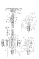
- a shower cubicle designated as a whole can be known Way any number of shower partitions 2, namely a single shower partition in a building niche or two shower partitions 2 in a building corner, as shown in Fig. 1 or also have three or four such shower partitions.
- at least one glass plate is provided, the one according to FIGS. 1 to 4 and according to FIGS. 13 and 14 Doors 4 pivotable about a vertical axis 3 or according to FIG. 11 and 12 a sliding door 4 or, according to FIGS. 5 to 7, a permanently installed glass wall 5 can be or have.
- the glass plate forming the door 4 or the fixed glass wall 5 has in all embodiments in its edge area one particularly clearly shown in FIGS. 9 and 10 Cutout 7 and one from cutout 7 to edge 8 extending opening 9 on the edge 8 on the one hand and on or on the other hand opens into the cutout 7, so that a total of one edge-open recess is formed.
- Fig. 2 In the upper part of Fig. 2 is an already installed fitting 6 as shown in Fig. 5, 11 and 13. It recognizes one each that between the facing each other Surfaces of the plate parts 10 and 11 in the use position a distance is provided.
- Clamping screws 13 are provided on the between the plate parts 10 and 11 clamped or clamped bearing element 14 run past. If the clamping screws are still loose 13 So can the bearing element 14 stepless, especially in its direction of longitudinal extension are adjusted and adjusted, which conversely an adjustment of the respective glass plate opposite their mounting or storage means.
- the plate parts 10 and 11 essentially forming the fitting 6 have a circular outline and that the one receiving them Section 7 - also according to FIG. 9 - up to the outside leading opening 9, so up to the opening slot, a has a circular inner contour, relative to that in its Dimension matched plate parts 10 and 11 loosened fastener 13 rotatable and adjustable are.
- Such a twist is from the Plastic or other lubricious material existing bushes 12 facilitated. This in the direction of rotation feasible adjustment can take place, even if the Clamping screws 13 are already tightened so far that a certain clamping and holding force also for the bearing element 14 is available.
- this bearing element is 14 a pin with a substantially circular cross-section, which at least in the area between the plate parts 10 and 11 is cone-shaped or bolt-shaped and thus well between the clamping screws 17 run and are clamped can.
- the over the edge 8 of the respective glass plate - door 4 or Glass wall 5 - protruding part of the bearing element 14 can according to 2 to 4 engage as a pin in an axial bearing or according to 11 and 12 to be connected to a trolley 18, the a mounting rail 18a is guided.
- the protruding area of the cone-shaped Bearing element 14 but also deformed, for example be bent over with an attachment to a building wall 19
- the Holding plate 20 not only a hole for the fastening screw 21, but also a groove-like recess 20a for gripping the bearing element, which in turn has a Has elongated hole 22 for the passage of the screw 21.
- the protruding part of the bearing element 14 could also have a different shape to use as a wall connection or connection to serve a camp.
- it could widen profiled, designed as a flange or provided with a flange be, such deformations also provided in combination could be.
- Fig. 6 shows, for example, that the bent Part is additionally profiled by that of the building wall facing area is flattened.
- the receiving the fitting 6 and its plate parts 10 and 11 Cutout 7 is from both sides with a conical taper provided on the inside, as you can see it particularly clearly in Fig. 10 recognizes.
- the taper leads to a common one central boundary surface or boundary edge 23, at which the cutout 7 has its smallest diameter dimension Has.
- the matching plate parts 10 and 11 and the associated Bushes 12 are at least as a counter cone partial or total immersion in flight with the Surface of the glass plate formed. You can see one sunken arrangement of the entire fitting 6 respectively its plate parts 10 and 11 z. 5 or 11.
- one of the Plate parts namely the plate part 11 according to FIG. 2 or 13 protruding from the glass surface in the shape of a spherical cap be formed so that the internal thread provided inside correspondingly longer for the clamping screws 13.
- An alternative mounting option could provide that the clamping or fastening screw 13 by one in the Bearing element 14 provided recess is passed through roughly analogous to the elongated hole 22 in the deformed part of the 6 shown bearing element 14. This could also Plate parts with the help of the clamping screws 13 to the outside of the bearing element 14 pressed and thereby clamped and additionally by the transverse clamping screws 13 being held.
- the plate parts 10 and 11 or fitting plate receiving cutout 7 the glass plate is larger than the edge opening 9, that means the diameter of the cutout 7 is larger than that Width of the opening 9.
- the center of this opening 9 runs in extension of a diameter of section 7 and at right angles to edge 8 of the glass plate, resulting in a symmetrical Arrangement leads, so that the glass plate in any orientation can be used and the fitting 6 always to the Cutout 7 fits.
- the fitting 6 in its two 180 ° opposing arrangements in the also Plate level symmetrical section 7 can be used.
- the opening 7 is formed as a slot, the Width exceeds that of the bearing element 14, so that this with Distance to the edges of the opening 9 through the opening 9 can.
- the pin-shaped bearing element 14 mentioned several times can according to the embodiment of FIGS. 13 and 14 also formed as a sleeve be, that is, have an interior longitudinal cavity into which Mounting position a pin or bolt 26 fits and engages, the part of a thrust bearing or a wall fitting or also a trolley 18 can be.
- the shower cubicle 1 has at least one shower partition 2 which can be formed by at least one glass plate, which a pivoting or sliding door 4 and / or a fixed glass wall 5 can be.
- the shower partition 2 forming or belonging to it Glass plate holding fittings 6 are provided for their attachment the glass plate has cutouts so that the fittings completely or partially sunk a bearing element approximately in the plane the glass plate over the edge 8 arranged and between two which essentially form the fitting 6 Plate parts 10 and 11 clamped by means of fasteners can be, this clamping also for fixation serves on the cutout 7 of the glass plate.
Landscapes
- Engineering & Computer Science (AREA)
- Health & Medical Sciences (AREA)
- Public Health (AREA)
- Mechanical Engineering (AREA)
- General Health & Medical Sciences (AREA)
- Epidemiology (AREA)
- Structural Engineering (AREA)
- Civil Engineering (AREA)
- Securing Of Glass Panes Or The Like (AREA)
- Hinges (AREA)
- Body Structure For Vehicles (AREA)
- Load-Bearing And Curtain Walls (AREA)
- Specific Sealing Or Ventilating Devices For Doors And Windows (AREA)
Abstract
Description
- Fig. 1
- Eine erfindungsgemäße Duschkabine mit zwei rechtwinklig zueinander angeordneten Duschtrennwänden, die je eine schwenkbare Türe und eine Glaswand aufweisen und in einer Gebäudeecke installiert sind,
- Fig. 2
- einen Längsschnitt einer als schwenkbare Türe ausgebildeten Glasplatte im Bereich der für die Schwenklagerung erforderlichen Beschläge, die dabei - auch gemäß Fig. 1 - mit Abstand zu dem Rand dieser Türe angeordnet sind, wobei die die Türe bildende Glasplatte Ausschnitte zum Installieren eines zwei Plattenteile und Klemmschrauben umfassenden Beschlags hat, der im Bereich eines unteren Schwenklagers in Explosionsdarstellung gezeichnet ist, wobei eines der Plattenteile in zwei verschiedenen möglichen Ausführungsformen dargestellt ist, wobei die Beschläge in einem Schnitt durch einen Durchmesser gezeichnet sind,
- Fig. 2a
- ein Plattenteil des Beschlags gemäß Fig. 2 in einem um 90° verdrehten Schnitt,
- Fig. 3
- eine teilweise im Längsschnitt gehaltene Ansicht der Lagerung der schwenkbaren Tür im Bereich ihres Beschlags und des damit zusammenwirkenden, an einer Duschtasse angeordneten Axiallagers,
- Fig. 4
- eine abgewandelte Ausführungsform und Darstellung gemäß Fig. 3, bei welcher das Axiallager so gestaltet ist, dass beim Verschwenken der Türe diese gleichzeitig angehoben wird,
- Fig. 5
- einen Schnitt durch den Randbereich einer fest installierten, als Glasplatte ausgebildeten Glaswand, bei welcher an dem Beschlag ein zapfenförmiges Lagerelement angreift, das außerhalb der Glasplatte rechtwinklig gegenüber seinem zwischen den Plattenteilen befindlichen Bereich verformt ist, wobei gleichzeitig die Befestigungsschraube und ein Klemmstück zum Erfassen dieses Lagerelements außerhalb des Beschlags auch in Ansicht und im Schnitt dargestellt sind,
- Fig.6
- in schaubildlicher Darstellung das Lagerelement gemäß Fig. 5, bei welchem der außerhalb des Beschlags befindliche umgebogene Teil zusätzlich abgeflacht ist,
- Fig. 7
- eine Ansicht des fest installierten Glaswandteils mit dem Beschlag gemäß Fig. 5,
- Fig. 8
- in Stirnansicht und Längsschnitt zwei unterschiedliche Ausführungsformen eines Verschlusses, der in einen Öffnungsschlitz an der Glasplatte passt, der den Ausschnitt für den Beschlag und den Rand der Glasplatte verbindet,
- Fig. 9
- eine Darstellung des Glasausschnitts und seiner Öffnung ohne eingesetzten Beschlag, wie er für die Türen oder fest installierten Glaswände zum Anbringen des erfindungsgemäßen Beschlags ausgebildet ist,
- Fig. 10
- einen Querschnitt durch eine Glasplatte im Bereich ihres Ausschnitts für den Beschlag etwa durch die Mitte des den Ausschnitt und den Rand verbindenden Öffnungsschlitzes,
- Fig. 11
- einen Schnitt durch einen Beschlag und eine Schiebetüre in ihrem Randbereich, wobei das von den Plattenteilen des Beschlags erfasste Lagerelement mit einem Rollwagen verbunden ist, der an einer Tragschiene verschiebbar ist,
- Fig. 12
- eine Ansicht des Beschlags einer Schiebetüre gemäß Fig. 11,
- Fig. 13
- einen Schnitt durch einen Beschlag und eine schwenkbare Türe im Bereich ihres unteren Schwenklagers, wobei das Lagerelement als Hülse ausgebildet ist, in welche ein zu dem Lager passender Stift eingreift , sowie
- Fig. 14
- eine teilweise im Längsschnitt gehaltene Ansicht der Lagerung einer schwenkbaren Türe mit Hilfe des erfindungsgemäßen Beschlags und einem hülsenförmigen Lagerelement gemäß Fig. 13, wobei die Halterung des Axiallagers an einer Duschtasse oder Wanne abgewandelt ausgebildet ist.
Claims (16)
- Duschkabine (1) mit zumindest einer Duschtrennwand (2), die wenigstens eine Glasplatte aufweist, welche durch eine um eine vertikale Achse (3) schwenkbare Türe (4) und/oder eine Schiebetüre (4) und/oder eine fest installierte Glaswand (5) gebildet ist, wobei zur Halterung der durch eine Türe (4) und/oder eine Glaswand (5) gebildeten Glasplatte wenigstens ein in deren Randbereich angreifender Beschlag (6) vorgesehen ist, dadurch gekennzeichnet, dass die die Türe (4) und/oder die feststehende Glaswand (5) bildende Glasplatte im Randbereich einen Ausschnitt (7) und eine von dem Ausschnitt (7) zum Rand (8) verlaufende Öffnung (9) hat, die an dem Rand (8) einerseits und an dem Ausschnitt (7) andererseits mündet, dass der Beschlag (6) zwei etwa parallele Plattenteile (10,11) aufweist, die in den Ausschnitt (7) passen und zumindest teilweise eingreifen und jeweils an der Glasplatte eine Anlage oder einen Anschlag haben, dass zwischen den einander zugewandten Flächen der Plattenteile (10,11) ein Abstand vorgesehen ist und dass wenigstens ein quer zu den Plattenteilen (10,11) wirkendes Befestigungselement (13) zum Verbinden und Verklemmen der Plattenteile (10,11) miteinander und mit der Glasplatte und zum gleichzeitigen Einklemmen eines Lagerelements (14) zwischen den Plattenteilen vorgesehen ist, wobei das Lagerelement (14) über die Plattenteile (10,11) und durch die randseitige Öffnung(9) des Ausschnitts (7) über die Glasplatte in Gebrauchsstellung übersteht.
- Duschkabine nach Anspruch 1, dadurch gekennzeichnet, dass das zum Verbinden der Plattenteile (10,11) und zum Einklemmen des Lagerelements (14) dienende Befestigungselement (13) ein die beiden Plattenelemente durchsetzendes Befestigungselement insbesondere eine oder mehrere Schrauben, ist.
- Duschkabine nach Anspruch 1 oder 2, dadurch gekennzeichnet, dass das Befestigungselement als Klemmschraube (13) ausgebildet ist, die mit einem Kopf (15)das eine Platteteil (10) und mit ihrem Gewinde (16) direkt oder indirekt das zweite Plattenteil (11) erfasst, so dass durch das Anziehen der Klemmschraube (13) die beiden beabstandeten Plattenteile (10,11) im Sinne einer Verminderung ihres Abstands verformbar sind.
- Duschkabine nach einem der Ansprüche 1 bis 3, dadurch gekennzeichnet, dass das oder die Befestigungselemente zum gegenseitigen Verspannen der Plattenteile, insbesondere die Klemmschraube(n) (13) in Gebrauchsstellung an dem zwischen den Plattenteilen (10,11) eingeklemmten Lagerelement (14) vorbei verlaufen.
- Duschkabine nach einem der Ansprüche 1 bis 4, dadurch gekennzeichnet, dass die den Beschlag (6) im Wesentlichen bildenden Plattenteile (10,11) zumindest bereichsweise eine kreisförmige Außenkontur oder insgesamt einen kreisförmigen Umriss haben und dass der sie aufnehmende Ausschnitt (7) in der Glasplatte bis zu der nach außen führenden Öffnung (9) oder einem Öffnungsschlitz eine kreisförmige Innenkontur hat, relativ zu der die Plattenteile (10,11) bei gelockertem Befestigungselement (13) verdrehbar und einstellbar sind.
- Duschkabine nach einem der Ansprüche 1 bis 5, dadurch gekennzeichnet, dass wenigstens eines der Plattenteile (11) an seiner inneren Fläche eine das Lagerelement (14) zumindest bereichsweise umgreifende, etwa rinnenförmige Ausnehmung (17) hat, die vorzugsweise durch die Mitte des Plattenteils (11) etwa auf einem Durchmesser verläuft.
- Duschkabine nach einem der Ansprüche 1 bis 6, dadurch gekennzeichnet, dass beide Plattenteile des Beschlags jeweils an den einander zugewandten Flächen miteinander korrespondierende Ausnehmungen(17) zum formschlüssigen Festlegen des von ihnen in Gebrauchsstellung eingeklemmten Lagerelements (14) haben.
- Duschkabine nach einem der Ansprüche 1 bis 7, dadurch gekennzeichnet, dass das Lagerelement (14) ein Zapfen ist oder zumindest in dem Bereich zwischen den Plattenteilen (10,11) zapfen- oder bolzenförmig ausgebildet ist.
- Duschkabine nach einem der Ansprüche 1 bis 8, dadurch gekennzeichnet, dass der über den Rand (8) der Glasplatte überstehende Teil des Lagerelements (14) als Zapfen in ein Axiallager eingreift oder mit einem Rollwagen (18) verbunden ist, der an einer Tragschiene geführt ist.
- Duschkabine nach einem der Ansprüche 1 bis 9, dadurch gekennzeichnet, dass der überstehende Bereich des insbesondere zapfenförmigen Lagerelements (14)verformt, beispielsweise umgebogen, verbreitert, profiliert als Flansch ausgebildet oder mit einem Flansch versehen ist.
- Duschkabine nach einem der Ansprüche 1 bis 10, dadurch gekennzeichnet, dass der den Beschlag (6) in Gebrauchsstellung aufnehmende Ausschnitt (7) an wenigstens einer Seite der Glasplatte eine konische Verjüngerung zum Inneren der Glasplatte hin hat und das dazu passende Plattenteil (10,11) seinerseits als Gegenkonus zum wenigstens teilweisen, vorzugsweise vollständigen Versenken dieses Plattenteils in die Flucht mit der Oberfläche dieser Glasplatte ausgebildet ist.
- Duschkabine nach einem der Ansprüche 1 bis 11, dadurch gekennzeichnet, dass eines der Plattenteile gegenüber der Glasoberfläche überstehend, beispielsweise kalottenförmig ausgebildet ist und vorzugsweise das oder die Innengewinde für die Klemmschraube(n) (13) enthält.
- Duschkabine nach einem der Ansprüche 1 bis 12, dadurch gekennzeichnet, dass das oder die Befestigungselemente, insbesondere eine oder mehrere Klemmschrauben (13) durch eine in dem Lagerelement (14) vorgesehene Ausnehmung hindurchgeführt ist/sind und dass die Plattenteile durch Anziehen dieser Befestigungselemente an die Außenseite des Lagerelements (14) andrückbar sind.
- Duschkabine nach einem der Ansprüche 1 bis 13, dadurch gekennzeichnet, dass der die Plattenteile (10,11) oder Beschlagplatten aufnehmende Ausschnitt (7) der Glasplatte größer als die randseitige Öffnung (9) diese Ausschnitts ist und dass die Mitte der randseitigen Öffnung vorzugsweise in Verlängerung eines Durchmessers des Ausschnitts (7) und rechtwinklig zum Rand (8) der Glasplatte verläuft und zum Beispiel als Schlitz ausgebildet ist, dessen Breite die des Lagerelements (14) übertrifft.
- Duschkabine nach einem der Ansprüche 1 bis 14, dadurch gekennzeichnet, dass in Gebrauchsstellung in dem randseitigen Öffnungsbereich oder -schlitz ein das durch diesen verlaufende Lagerelement (14) umschließendes Verschlussteil (24) einsetzbar, beispielsweise auf das Lagerelement (14) aufsteckbar ist.
- Duschkabine, nach einem der Ansprüche 1 bis 15, dadurch gekennzeichnet, dass das vorzugsweise zapfenförmige Lagerelement (14) eine Innenlängshöhlung hat und als Hülse ausgebildet ist, in die in Montagestellung ein Stift oder Bolzen (26) passt, der Teil eines Axiallagers oder eines Wandbeschlags oder eines Rollwagens (18) ist.
Applications Claiming Priority (2)
| Application Number | Priority Date | Filing Date | Title |
|---|---|---|---|
| DE10211709 | 2002-03-16 | ||
| DE2002111709 DE10211709C1 (de) | 2002-03-16 | 2002-03-16 | Duschkabine mit einer wenigstens eine Glasplatte aufweisenden Duschtrennwand |
Publications (2)
| Publication Number | Publication Date |
|---|---|
| EP1344478A1 true EP1344478A1 (de) | 2003-09-17 |
| EP1344478B1 EP1344478B1 (de) | 2007-12-05 |
Family
ID=27762952
Family Applications (1)
| Application Number | Title | Priority Date | Filing Date |
|---|---|---|---|
| EP03004053A Expired - Lifetime EP1344478B1 (de) | 2002-03-16 | 2003-02-25 | Duschkabine mit einer wenigstens eine Glasplatte aufweisenden Duschtrennwand |
Country Status (3)
| Country | Link |
|---|---|
| EP (1) | EP1344478B1 (de) |
| AT (1) | ATE379987T1 (de) |
| DE (2) | DE10211709C1 (de) |
Cited By (3)
| Publication number | Priority date | Publication date | Assignee | Title |
|---|---|---|---|---|
| EP1614842A2 (de) | 2004-07-05 | 2006-01-11 | DORMA GmbH + Co. KG | Beschlag zur Aufhängung einer Glasscheibe |
| GB2444398A (en) * | 2006-11-28 | 2008-06-04 | Brik Group Ltd | Modular Shower Enclosure |
| EP3626141A1 (de) * | 2018-09-20 | 2020-03-25 | Gebr. Willach GmbH | Abtrennungswand einer duschkabine oder dusch- oder badewannenabtrennung |
Families Citing this family (1)
| Publication number | Priority date | Publication date | Assignee | Title |
|---|---|---|---|---|
| DE102012019778B4 (de) | 2012-10-09 | 2014-10-02 | Combia GmbH | Breitenverstellbare Haltevorrichtung für eine rahmenlose Wannenabtrennung und mit dieser ausgestattete Wannenabtrennung sowie Verwendung eines Verstellelements zur Breitenverstellung einer Wannenabtrennung |
Citations (5)
| Publication number | Priority date | Publication date | Assignee | Title |
|---|---|---|---|---|
| DE3901395A1 (de) * | 1989-01-19 | 1990-08-02 | Munch Paul Jean | Schwenktuere fuer duschtrennwand |
| US6070294A (en) * | 1996-09-23 | 2000-06-06 | George Fethers & Co. Trading Pty Ltd | Hinge for a shower screen door |
| EP1038488A2 (de) * | 1999-03-22 | 2000-09-27 | Altura Leiden Holding B.V. | Duschabtrennung |
| DE10027896A1 (de) * | 2000-06-06 | 2002-01-03 | Peter Leitgeb | Vorrichtung zur lösbaren Halterung von wenigstens zwei Flächenelementen und deren Verwendung |
| EP1170513A2 (de) * | 2000-06-06 | 2002-01-09 | Joachim Fischbach | Vorrichtung zur lösbaren Halterung von wenigstens zwei Flächenelementen und deren Verwendung |
Family Cites Families (1)
| Publication number | Priority date | Publication date | Assignee | Title |
|---|---|---|---|---|
| EP0036207B1 (de) * | 1980-03-15 | 1984-10-24 | Frank Huster | Kabine mit Eintrittsöffnung und Tür zum Abschirmen des Raumes nach aussen |
-
2002
- 2002-03-16 DE DE2002111709 patent/DE10211709C1/de not_active Expired - Fee Related
-
2003
- 2003-02-25 EP EP03004053A patent/EP1344478B1/de not_active Expired - Lifetime
- 2003-02-25 DE DE50308715T patent/DE50308715D1/de not_active Expired - Fee Related
- 2003-02-25 AT AT03004053T patent/ATE379987T1/de not_active IP Right Cessation
Patent Citations (5)
| Publication number | Priority date | Publication date | Assignee | Title |
|---|---|---|---|---|
| DE3901395A1 (de) * | 1989-01-19 | 1990-08-02 | Munch Paul Jean | Schwenktuere fuer duschtrennwand |
| US6070294A (en) * | 1996-09-23 | 2000-06-06 | George Fethers & Co. Trading Pty Ltd | Hinge for a shower screen door |
| EP1038488A2 (de) * | 1999-03-22 | 2000-09-27 | Altura Leiden Holding B.V. | Duschabtrennung |
| DE10027896A1 (de) * | 2000-06-06 | 2002-01-03 | Peter Leitgeb | Vorrichtung zur lösbaren Halterung von wenigstens zwei Flächenelementen und deren Verwendung |
| EP1170513A2 (de) * | 2000-06-06 | 2002-01-09 | Joachim Fischbach | Vorrichtung zur lösbaren Halterung von wenigstens zwei Flächenelementen und deren Verwendung |
Cited By (5)
| Publication number | Priority date | Publication date | Assignee | Title |
|---|---|---|---|---|
| EP1614842A2 (de) | 2004-07-05 | 2006-01-11 | DORMA GmbH + Co. KG | Beschlag zur Aufhängung einer Glasscheibe |
| EP1614842A3 (de) * | 2004-07-05 | 2009-08-12 | DORMA GmbH + Co. KG | Beschlag zur Aufhängung einer Glasscheibe |
| GB2444398A (en) * | 2006-11-28 | 2008-06-04 | Brik Group Ltd | Modular Shower Enclosure |
| EP3626141A1 (de) * | 2018-09-20 | 2020-03-25 | Gebr. Willach GmbH | Abtrennungswand einer duschkabine oder dusch- oder badewannenabtrennung |
| EP3626141B1 (de) | 2018-09-20 | 2021-06-23 | Gebr. Willach GmbH | Abtrennungswand einer duschkabine oder dusch- oder badewannenabtrennung |
Also Published As
| Publication number | Publication date |
|---|---|
| ATE379987T1 (de) | 2007-12-15 |
| DE50308715D1 (de) | 2008-01-17 |
| EP1344478B1 (de) | 2007-12-05 |
| DE10211709C1 (de) | 2003-11-06 |
Similar Documents
| Publication | Publication Date | Title |
|---|---|---|
| AT394081B (de) | Verstellbares tuer- und fensterband | |
| AT509796B1 (de) | Hohlprofil | |
| WO2004106679A1 (de) | Schiebetür | |
| DE202012008665U1 (de) | Anordnung zum Befestigen eines Pfostens an einer Rahmenleiste eines Fensters oder einer Türe mittels eines Pfostenverbinders | |
| AT511046B1 (de) | Rahmensystem eines partikelschutzgitters | |
| EP3103948B1 (de) | Band für eine tür oder ein fenster | |
| EP2366857B1 (de) | Befestigungsanordnung für eine Schiebetür | |
| AT18487U1 (de) | Verbesserte Inpektionsklapptür | |
| DE102006016045B4 (de) | Vorrichtung zur lösbaren Halterung von einem Flächenelement und deren Verwendung | |
| EP1231347B1 (de) | Fensterladen mit wenigstens zwei Befestigungsbändern | |
| EP2345787B1 (de) | Türband für Aluminiumtüren | |
| EP0976891B1 (de) | Aufbausystem | |
| DE202012105001U1 (de) | Türsystem | |
| DE202016101091U1 (de) | Türverriegelung | |
| DE102012111547B3 (de) | Türband | |
| DE10211709C1 (de) | Duschkabine mit einer wenigstens eine Glasplatte aufweisenden Duschtrennwand | |
| EP2320022B1 (de) | Scharnier für ein Insekten- und/oder Pollenschutzgitter | |
| WO2004085780A1 (de) | Band, insbesondere für dusch- und/oder glastüren | |
| EP0592854B1 (de) | Lösbare Türdrückerverbindung | |
| EP2108774B1 (de) | Beschlag | |
| DE202011052447U1 (de) | Anordnung einer Antriebseinheit einer Ausstell- oder Verriegelungseinrichtung | |
| EP1659246A1 (de) | Scharnierbeschlag für Fensterläden | |
| EP1560996A1 (de) | Beschlaganordnung für glastüren | |
| EP1038486B1 (de) | Bausatz für Duschabtrennungen | |
| DE29923347U1 (de) | Befestigungsvorrichtung für eine Duschabtrennung |
Legal Events
| Date | Code | Title | Description |
|---|---|---|---|
| PUAI | Public reference made under article 153(3) epc to a published international application that has entered the european phase |
Free format text: ORIGINAL CODE: 0009012 |
|
| AK | Designated contracting states |
Kind code of ref document: A1 Designated state(s): AT BE BG CH CY CZ DE DK EE ES FI FR GB GR HU IE IT LI LU MC NL PT SE SI SK TR |
|
| AX | Request for extension of the european patent |
Extension state: AL LT LV MK RO |
|
| RAP1 | Party data changed (applicant data changed or rights of an application transferred) |
Owner name: DORMA GMBH + CO. KG |
|
| RIN1 | Information on inventor provided before grant (corrected) |
Inventor name: MUNCH, PAUL-JEAN |
|
| AKX | Designation fees paid | ||
| REG | Reference to a national code |
Ref country code: HK Ref legal event code: DE Ref document number: 1059105 Country of ref document: HK |
|
| 17P | Request for examination filed |
Effective date: 20040513 |
|
| RBV | Designated contracting states (corrected) |
Designated state(s): AT BE BG CH CY CZ DE DK EE ES FI FR GB GR HU IE IT LI LU MC NL PT SE SI SK TR |
|
| REG | Reference to a national code |
Ref country code: DE Ref legal event code: 8566 |
|
| 17Q | First examination report despatched |
Effective date: 20040624 |
|
| GRAP | Despatch of communication of intention to grant a patent |
Free format text: ORIGINAL CODE: EPIDOSNIGR1 |
|
| GRAS | Grant fee paid |
Free format text: ORIGINAL CODE: EPIDOSNIGR3 |
|
| GRAA | (expected) grant |
Free format text: ORIGINAL CODE: 0009210 |
|
| AK | Designated contracting states |
Kind code of ref document: B1 Designated state(s): AT BE BG CH CY CZ DE DK EE ES FI FR GB GR HU IE IT LI LU MC NL PT SE SI SK TR |
|
| REG | Reference to a national code |
Ref country code: GB Ref legal event code: FG4D Free format text: NOT ENGLISH |
|
| REG | Reference to a national code |
Ref country code: IE Ref legal event code: FG4D Free format text: LANGUAGE OF EP DOCUMENT: GERMAN |
|
| REG | Reference to a national code |
Ref country code: CH Ref legal event code: EP |
|
| REF | Corresponds to: |
Ref document number: 50308715 Country of ref document: DE Date of ref document: 20080117 Kind code of ref document: P |
|
| PG25 | Lapsed in a contracting state [announced via postgrant information from national office to epo] |
Ref country code: ES Free format text: LAPSE BECAUSE OF FAILURE TO SUBMIT A TRANSLATION OF THE DESCRIPTION OR TO PAY THE FEE WITHIN THE PRESCRIBED TIME-LIMIT Effective date: 20080316 Ref country code: NL Free format text: LAPSE BECAUSE OF FAILURE TO SUBMIT A TRANSLATION OF THE DESCRIPTION OR TO PAY THE FEE WITHIN THE PRESCRIBED TIME-LIMIT Effective date: 20071205 Ref country code: SE Free format text: LAPSE BECAUSE OF FAILURE TO SUBMIT A TRANSLATION OF THE DESCRIPTION OR TO PAY THE FEE WITHIN THE PRESCRIBED TIME-LIMIT Effective date: 20080305 |
|
| PG25 | Lapsed in a contracting state [announced via postgrant information from national office to epo] |
Ref country code: SI Free format text: LAPSE BECAUSE OF FAILURE TO SUBMIT A TRANSLATION OF THE DESCRIPTION OR TO PAY THE FEE WITHIN THE PRESCRIBED TIME-LIMIT Effective date: 20071205 Ref country code: FI Free format text: LAPSE BECAUSE OF FAILURE TO SUBMIT A TRANSLATION OF THE DESCRIPTION OR TO PAY THE FEE WITHIN THE PRESCRIBED TIME-LIMIT Effective date: 20071205 |
|
| NLV1 | Nl: lapsed or annulled due to failure to fulfill the requirements of art. 29p and 29m of the patents act | ||
| GBV | Gb: ep patent (uk) treated as always having been void in accordance with gb section 77(7)/1977 [no translation filed] | ||
| PG25 | Lapsed in a contracting state [announced via postgrant information from national office to epo] |
Ref country code: CZ Free format text: LAPSE BECAUSE OF FAILURE TO SUBMIT A TRANSLATION OF THE DESCRIPTION OR TO PAY THE FEE WITHIN THE PRESCRIBED TIME-LIMIT Effective date: 20071205 |
|
| PG25 | Lapsed in a contracting state [announced via postgrant information from national office to epo] |
Ref country code: SK Free format text: LAPSE BECAUSE OF FAILURE TO SUBMIT A TRANSLATION OF THE DESCRIPTION OR TO PAY THE FEE WITHIN THE PRESCRIBED TIME-LIMIT Effective date: 20071205 |
|
| BERE | Be: lapsed |
Owner name: DORMA G.M.B.H. + CO. KG Effective date: 20080228 |
|
| PG25 | Lapsed in a contracting state [announced via postgrant information from national office to epo] |
Ref country code: PT Free format text: LAPSE BECAUSE OF FAILURE TO SUBMIT A TRANSLATION OF THE DESCRIPTION OR TO PAY THE FEE WITHIN THE PRESCRIBED TIME-LIMIT Effective date: 20080505 |
|
| REG | Reference to a national code |
Ref country code: CH Ref legal event code: PL |
|
| REG | Reference to a national code |
Ref country code: IE Ref legal event code: FD4D |
|
| EN | Fr: translation not filed | ||
| PLBE | No opposition filed within time limit |
Free format text: ORIGINAL CODE: 0009261 |
|
| STAA | Information on the status of an ep patent application or granted ep patent |
Free format text: STATUS: NO OPPOSITION FILED WITHIN TIME LIMIT |
|
| REG | Reference to a national code |
Ref country code: HK Ref legal event code: WD Ref document number: 1059105 Country of ref document: HK |
|
| PG25 | Lapsed in a contracting state [announced via postgrant information from national office to epo] |
Ref country code: DK Free format text: LAPSE BECAUSE OF FAILURE TO SUBMIT A TRANSLATION OF THE DESCRIPTION OR TO PAY THE FEE WITHIN THE PRESCRIBED TIME-LIMIT Effective date: 20071205 Ref country code: MC Free format text: LAPSE BECAUSE OF NON-PAYMENT OF DUE FEES Effective date: 20080228 Ref country code: CH Free format text: LAPSE BECAUSE OF NON-PAYMENT OF DUE FEES Effective date: 20080229 Ref country code: IE Free format text: LAPSE BECAUSE OF FAILURE TO SUBMIT A TRANSLATION OF THE DESCRIPTION OR TO PAY THE FEE WITHIN THE PRESCRIBED TIME-LIMIT Effective date: 20071205 Ref country code: LI Free format text: LAPSE BECAUSE OF NON-PAYMENT OF DUE FEES Effective date: 20080229 |
|
| 26N | No opposition filed |
Effective date: 20080908 |
|
| PG25 | Lapsed in a contracting state [announced via postgrant information from national office to epo] |
Ref country code: GB Free format text: LAPSE BECAUSE OF FAILURE TO SUBMIT A TRANSLATION OF THE DESCRIPTION OR TO PAY THE FEE WITHIN THE PRESCRIBED TIME-LIMIT Effective date: 20071205 |
|
| PG25 | Lapsed in a contracting state [announced via postgrant information from national office to epo] |
Ref country code: GR Free format text: LAPSE BECAUSE OF FAILURE TO SUBMIT A TRANSLATION OF THE DESCRIPTION OR TO PAY THE FEE WITHIN THE PRESCRIBED TIME-LIMIT Effective date: 20080306 Ref country code: DE Free format text: LAPSE BECAUSE OF NON-PAYMENT OF DUE FEES Effective date: 20080902 Ref country code: EE Free format text: LAPSE BECAUSE OF FAILURE TO SUBMIT A TRANSLATION OF THE DESCRIPTION OR TO PAY THE FEE WITHIN THE PRESCRIBED TIME-LIMIT Effective date: 20071205 |
|
| PG25 | Lapsed in a contracting state [announced via postgrant information from national office to epo] |
Ref country code: BE Free format text: LAPSE BECAUSE OF NON-PAYMENT OF DUE FEES Effective date: 20080228 |
|
| PG25 | Lapsed in a contracting state [announced via postgrant information from national office to epo] |
Ref country code: AT Free format text: LAPSE BECAUSE OF NON-PAYMENT OF DUE FEES Effective date: 20080225 Ref country code: BG Free format text: LAPSE BECAUSE OF FAILURE TO SUBMIT A TRANSLATION OF THE DESCRIPTION OR TO PAY THE FEE WITHIN THE PRESCRIBED TIME-LIMIT Effective date: 20080305 Ref country code: FR Free format text: LAPSE BECAUSE OF FAILURE TO SUBMIT A TRANSLATION OF THE DESCRIPTION OR TO PAY THE FEE WITHIN THE PRESCRIBED TIME-LIMIT Effective date: 20081003 |
|
| PG25 | Lapsed in a contracting state [announced via postgrant information from national office to epo] |
Ref country code: CY Free format text: LAPSE BECAUSE OF FAILURE TO SUBMIT A TRANSLATION OF THE DESCRIPTION OR TO PAY THE FEE WITHIN THE PRESCRIBED TIME-LIMIT Effective date: 20071205 |
|
| PG25 | Lapsed in a contracting state [announced via postgrant information from national office to epo] |
Ref country code: HU Free format text: LAPSE BECAUSE OF FAILURE TO SUBMIT A TRANSLATION OF THE DESCRIPTION OR TO PAY THE FEE WITHIN THE PRESCRIBED TIME-LIMIT Effective date: 20080606 Ref country code: LU Free format text: LAPSE BECAUSE OF NON-PAYMENT OF DUE FEES Effective date: 20080225 |
|
| PG25 | Lapsed in a contracting state [announced via postgrant information from national office to epo] |
Ref country code: TR Free format text: LAPSE BECAUSE OF FAILURE TO SUBMIT A TRANSLATION OF THE DESCRIPTION OR TO PAY THE FEE WITHIN THE PRESCRIBED TIME-LIMIT Effective date: 20071205 |
|
| PG25 | Lapsed in a contracting state [announced via postgrant information from national office to epo] |
Ref country code: IT Free format text: LAPSE BECAUSE OF NON-PAYMENT OF DUE FEES Effective date: 20080229 |