EP1344472A1 - Anordnung zur Sicherung eines ausgezogenen Einschubs in einem Rack - Google Patents
Anordnung zur Sicherung eines ausgezogenen Einschubs in einem Rack Download PDFInfo
- Publication number
- EP1344472A1 EP1344472A1 EP03004662A EP03004662A EP1344472A1 EP 1344472 A1 EP1344472 A1 EP 1344472A1 EP 03004662 A EP03004662 A EP 03004662A EP 03004662 A EP03004662 A EP 03004662A EP 1344472 A1 EP1344472 A1 EP 1344472A1
- Authority
- EP
- European Patent Office
- Prior art keywords
- arrangement according
- insert
- rack
- locking
- telescopic rails
- Prior art date
- Legal status (The legal status is an assumption and is not a legal conclusion. Google has not performed a legal analysis and makes no representation as to the accuracy of the status listed.)
- Granted
Links
Images

Classifications
-
- A—HUMAN NECESSITIES
- A47—FURNITURE; DOMESTIC ARTICLES OR APPLIANCES; COFFEE MILLS; SPICE MILLS; SUCTION CLEANERS IN GENERAL
- A47B—TABLES; DESKS; OFFICE FURNITURE; CABINETS; DRAWERS; GENERAL DETAILS OF FURNITURE
- A47B88/00—Drawers for tables, cabinets or like furniture; Guides for drawers
- A47B88/40—Sliding drawers; Slides or guides therefor
- A47B88/433—Drawers with a couple of pivotally retractable, roller-supporting arms at the rear of the drawer, e.g. for curved slides or guides
Definitions
- the invention relates to an arrangement for securing an Telescopic slides in a rack.
- racks are placed in a rack on telescopic rails hung up on which they are then pulled out of the rack can be. It is known that some telescopic rails Devices are provided through which too easy insertion is prevented.
- the invention is therefore based on the object, the telescopic rails relieve the weight of the inserts and a safe protection against the complete overturning of the Ensure racks.
- the object is achieved in that in the extended Condition an insert with a lock below the telescopic rails on which the drawer is hung is, is fixed.
- An advantage of locking is that the extended Insert is also stabilized laterally.
- the lateral fixation and stabilization in the extended state of the insert is particularly important when changing modules from the side, because there are great stresses on the plug-in and the Telescopic rails work.
- Another advantage is that when locked in place Tilting forward is only possible until the front The bottom edge of the extended shelf touches the floor.
- the locking also results in lateral guidance and stability when inserted. Especially when As a result, transport forces on the telescopic rails are too great avoided.
- Figure 1 shows a side view of a rack 4 with one Telescopic rails 2 extended insert 3 and an inventive Lock 1.
- FIG. 2 shows a section through the arrangement of FIG. 1, with the lock 1 and a guide rail 9.
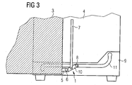
- a locking button 8 On the side of the locking rod opposite the swivel 6 10 is a locking button 8, which in one Guide slot 11 of the guide rail 9 engages and in this is led.
- the guide rail 9 consists of a metal rail into which the guide slot 11 is milled so that when complete extended slide 3 of the locking button 8 snaps into place.
- An unlocking is between the locking button 8 and the swivel 6 7 attached to the locking rod 10 so after train moved up that the locking button 8 out of its locked Disengages position and freely movable in the guide slot 11 is.
- Figure 3 shows a view according to Figure 2 with half inserted Insert 3, which the mobility of the locking rod shows.
Landscapes
- Drawers Of Furniture (AREA)
- Warehouses Or Storage Devices (AREA)
Abstract
Description
- Figur 1
- eine Seitenansicht eines Racks mit einem ausgezogenen Einschub und einer festgelegten Arretierung,
- Figur 2
- einen Schnitt durch ein Rack und einen Einschub mit Blick auf die Arretierung,
- Figur 3
- eine Ansicht gemäß Figur 2 mit halb eingeschobenem Einschub.
- 1
- Arretierung
- 2
- Teleskopschiene
- 3
- Einschub
- 4
- Rack
- 5
- Halterung
- 6
- Drehgelenk
- 7
- Entriegelung
- 8
- Arretierknopf
- 9
- Führungsschiene
- 10
- Arretierstab
- 11
- Führungsschlitz
Claims (13)
- Anordnung zur Sicherung eines an Teleskopschienen (2) ausgezogenen Einschubes (3) in einem Rack (4),
dadurch gekennzeichnet, dass im ausgezogenen Zustand der Einschub (3) mit einer Arretierung (1) unterhalb der Teleskopschienen (2) festgelegt ist. - Anordnung nach Anspruch 1,
dadurch gekennzeichnet, dass durch die Arretierung (1) die Gewichtskraft des Einschubes (3) auf das Rack (4) umgelenkt ist. - Anordnung nach Anspruch 1 oder 2,
dadurch gekennzeichnet, dass in arretiertem Zustand die Teleskopschienen (2) von der vertikal wirkenden Gewichtskraft entlastet und nur noch auf Zug belastet sind. - Anordnung nach einem der Ansprüche 1 bis 3,
dadurch gekennzeichnet, dass die Arretierung (1) eine Halterung (5) an der Rückseite des Einschubes (3) aufweist. - Anordnung nach einem der Ansprüche 1 bis 4,
dadurch gekennzeichnet, dass eine Seite eines Arretierstabes (10) über ein Drehgelenk (6) mit der Halterung (5) drehbar verbunden ist. - Anordnung nach einem der Ansprüche 1 bis 5,
dadurch gekennzeichnet, dass die andere Seite des Arretierstabes (10) einen Arretierknopf (8) aufweist, der in eine Führungsschiene (9) eingreift.. - Anordnung nach einem der Ansprüche 1 bis 6,
dadurch gekennzeichnet, dass die Führungsschiene (9) aus einer Metallschiene mit Führungsschlitz (11) gebildet ist. - Anordnung nach einem der Ansprüche 1 bis 7,
dadurch gekennzeichnet, dass am vorderen Ende des Führungsschlitzes (11) eine Aussparung (12) ausgebildet ist. - Anordnung nach einem der Ansprüche 1 bis 8,
dadurch gekennzeichnet, dass an der Arretierung (1) eine Entriegelung (7) ausgebildet ist. - Anordnung nach einem der Ansprüche 1 bis 9,
dadurch gekennzeichnet, dass die Arretierung (1) den Einschub (3) seitlich festlegt. - Anordnung nach einem der Ansprüche 1 bis 10,
dadurch gekennzeichnet, dass der Einschub (3) mit eingerasteter Arretierung (1) eine Stütze gegen ein Umkippen des Racks (4) nach vorne ist. - Anordnung nach einem der Ansprüche 1 bis 11,
dadurch gekennzeichnet, dass
der Einschub (3) im eingeschobenen Zustand so arretiert ist, daß beim Transport eine seitliche Führung und Stabilität gegeben ist. - Anordnung nach einem der Ansprüche 1 bis 10,
dadurch gekennzeichnet, dass der Einschub (3) im ausgezogenen Zustand so arretiert ist, daß bei seitlich auftretenden Kräften eine seitliche Fixierung und Stabilität gegeben ist.
Applications Claiming Priority (2)
| Application Number | Priority Date | Filing Date | Title |
|---|---|---|---|
| DE10210609A DE10210609B4 (de) | 2002-03-11 | 2002-03-11 | Anordnung zur Sicherung eines ausgezogenen Einschubs in einem Rack |
| DE10210609 | 2002-03-11 |
Publications (2)
| Publication Number | Publication Date |
|---|---|
| EP1344472A1 true EP1344472A1 (de) | 2003-09-17 |
| EP1344472B1 EP1344472B1 (de) | 2010-05-19 |
Family
ID=27762857
Family Applications (1)
| Application Number | Title | Priority Date | Filing Date |
|---|---|---|---|
| EP03004662A Expired - Lifetime EP1344472B1 (de) | 2002-03-11 | 2003-03-03 | Anordnung zur Sicherung eines ausgezogenen Einschubs in einem Rack |
Country Status (3)
| Country | Link |
|---|---|
| EP (1) | EP1344472B1 (de) |
| AT (1) | ATE468043T1 (de) |
| DE (1) | DE10210609B4 (de) |
Families Citing this family (1)
| Publication number | Priority date | Publication date | Assignee | Title |
|---|---|---|---|---|
| DE102014103948B4 (de) * | 2014-03-21 | 2018-10-25 | Andreas Hettich Gmbh & Co. Kg | Inkubator |
Citations (2)
| Publication number | Priority date | Publication date | Assignee | Title |
|---|---|---|---|---|
| DE2946113A1 (de) * | 1979-11-15 | 1981-05-21 | Erich 6483 Bad Soden-Salmünster Löhnert | Auszugsbeschlag fuer einen schubkasten |
| EP0512615A1 (de) * | 1991-05-02 | 1992-11-11 | Thomas Regout N.V. | System um das Verkanten von Schubladen zu verhindern |
Family Cites Families (7)
| Publication number | Priority date | Publication date | Assignee | Title |
|---|---|---|---|---|
| DE7116994U (de) * | 1971-08-05 | Dyes & Co | Buroschrank | |
| DE7148503U (de) * | Ziehl G | Auszugsvorrichtung für Schubladen | ||
| US2730423A (en) * | 1953-05-22 | 1956-01-10 | Joseph P Mock | Cabinet drawer stop construction |
| DE6906361U (de) * | 1969-02-18 | 1970-09-03 | Leopold Knappek Kg Elka Buerom | Auszugssperre fuer mehrere in schraenken uebereinander angeordnete schubladen mit zentralverschluss |
| NL7104555A (de) * | 1971-04-05 | 1972-10-09 | ||
| AT400212B (de) * | 1992-05-12 | 1995-11-27 | Svoboda Moebelwerk | Auszugsperre für schubladen |
| DE29507917U1 (de) * | 1995-05-17 | 1995-08-17 | Hettich Paul Gmbh & Co | Schubkastenauszugsführung |
-
2002
- 2002-03-11 DE DE10210609A patent/DE10210609B4/de not_active Expired - Fee Related
-
2003
- 2003-03-03 AT AT03004662T patent/ATE468043T1/de active
- 2003-03-03 EP EP03004662A patent/EP1344472B1/de not_active Expired - Lifetime
Patent Citations (2)
| Publication number | Priority date | Publication date | Assignee | Title |
|---|---|---|---|---|
| DE2946113A1 (de) * | 1979-11-15 | 1981-05-21 | Erich 6483 Bad Soden-Salmünster Löhnert | Auszugsbeschlag fuer einen schubkasten |
| EP0512615A1 (de) * | 1991-05-02 | 1992-11-11 | Thomas Regout N.V. | System um das Verkanten von Schubladen zu verhindern |
Also Published As
| Publication number | Publication date |
|---|---|
| EP1344472B1 (de) | 2010-05-19 |
| DE10210609A1 (de) | 2003-10-02 |
| ATE468043T1 (de) | 2010-06-15 |
| DE10210609B4 (de) | 2004-02-19 |
Similar Documents
| Publication | Publication Date | Title |
|---|---|---|
| EP3658339B1 (de) | Aufbewahrungskasten und regal | |
| DE202022101496U1 (de) | Regal | |
| DE2131772A1 (de) | Geraeteschrank mit Schwenkrahmen | |
| EP4022158B1 (de) | Möbelstück, insbesondere ein schrank | |
| DE102006018421A1 (de) | System zur Sicherung von kippgefährdeten Möbeln und Gerätschaften | |
| DE19712681C1 (de) | Nachttisch | |
| EP2477791B1 (de) | Behälter zum aufbewahren von gegenständen | |
| DE102011050823B4 (de) | Werkzeugbehälter | |
| DE10210609B4 (de) | Anordnung zur Sicherung eines ausgezogenen Einschubs in einem Rack | |
| EP1441092A1 (de) | Schliessvorrichtung für Schubladenschränke | |
| AT398517B (de) | Schublade | |
| DE3401170A1 (de) | Moebelstueck mit einer versenkbaren tischplatte | |
| DE102017113197A1 (de) | Transportbox | |
| EP0035595A2 (de) | Vorrichtung zur lösbaren Befestigung eines aus einem Gestell ausziehbaren Trägers | |
| DE102017110499A1 (de) | Hubmechanismus mit einer Ablage, Möbel und Schubkasten | |
| DE20012761U1 (de) | Lagereinrichtung, insbesondere Regal oder Schrank mit frontseitigem Verschlußsystem | |
| DE202008005728U1 (de) | Verpackung | |
| DE1951215A1 (de) | Schubladenfuehrungseinrichtung | |
| DE9104404U1 (de) | Gestell zur Aufnahme von bevorzugt vertikal zu lagernden Gegenständen | |
| DE4434933C2 (de) | Verschluß zur zentralen Ver- und Entriegelung von Schubladen | |
| DE8515172U1 (de) | Schnappverriegelung für ausziehbare Schubfächer | |
| DE20103207U1 (de) | Auszug für ein Möbel | |
| DE10009358B4 (de) | Tisch, insbesondere Arbeitstisch | |
| DE650182C (de) | In der Hoehe verstellbare Auszuege in Schraenken, Regalen u. dgl. | |
| DE3615720A1 (de) | Schnappverriegelung fuer ausziehbare schubfaecher |
Legal Events
| Date | Code | Title | Description |
|---|---|---|---|
| PUAI | Public reference made under article 153(3) epc to a published international application that has entered the european phase |
Free format text: ORIGINAL CODE: 0009012 |
|
| AK | Designated contracting states |
Kind code of ref document: A1 Designated state(s): AT BE BG CH CY CZ DE DK EE ES FI FR GB GR HU IE IT LI LU MC NL PT RO SE SI SK TR |
|
| AX | Request for extension of the european patent |
Extension state: AL LT LV MK |
|
| 17P | Request for examination filed |
Effective date: 20040217 |
|
| RAP1 | Party data changed (applicant data changed or rights of an application transferred) |
Owner name: FUJITSU SIEMENS COMPUTERS GMBH |
|
| AKX | Designation fees paid |
Designated state(s): AT BE BG CH CY CZ DE DK EE ES FI FR GB GR HU IE IT LI LU MC NL PT RO SE SI SK TR |
|
| 17Q | First examination report despatched |
Effective date: 20060928 |
|
| GRAP | Despatch of communication of intention to grant a patent |
Free format text: ORIGINAL CODE: EPIDOSNIGR1 |
|
| GRAS | Grant fee paid |
Free format text: ORIGINAL CODE: EPIDOSNIGR3 |
|
| GRAA | (expected) grant |
Free format text: ORIGINAL CODE: 0009210 |
|
| RBV | Designated contracting states (corrected) |
Designated state(s): AT BE BG CH CY CZ DK EE ES FI FR GB GR HU IE IT LI LU MC NL PT RO SE SI SK TR |
|
| AK | Designated contracting states |
Kind code of ref document: B1 Designated state(s): AT BE BG CH CY CZ DK EE ES FI FR GB GR HU IE IT LI LU MC NL PT RO SE SI SK TR |
|
| REG | Reference to a national code |
Ref country code: GB Ref legal event code: FG4D Free format text: NOT ENGLISH |
|
| REG | Reference to a national code |
Ref country code: CH Ref legal event code: EP |
|
| REG | Reference to a national code |
Ref country code: DE Ref legal event code: 8566 |
|
| REG | Reference to a national code |
Ref country code: IE Ref legal event code: FG4D Free format text: LANGUAGE OF EP DOCUMENT: GERMAN |
|
| REG | Reference to a national code |
Ref country code: NL Ref legal event code: VDEP Effective date: 20100519 |
|
| PG25 | Lapsed in a contracting state [announced via postgrant information from national office to epo] |
Ref country code: SE Free format text: LAPSE BECAUSE OF FAILURE TO SUBMIT A TRANSLATION OF THE DESCRIPTION OR TO PAY THE FEE WITHIN THE PRESCRIBED TIME-LIMIT Effective date: 20100519 Ref country code: ES Free format text: LAPSE BECAUSE OF FAILURE TO SUBMIT A TRANSLATION OF THE DESCRIPTION OR TO PAY THE FEE WITHIN THE PRESCRIBED TIME-LIMIT Effective date: 20100830 |
|
| PG25 | Lapsed in a contracting state [announced via postgrant information from national office to epo] |
Ref country code: SI Free format text: LAPSE BECAUSE OF FAILURE TO SUBMIT A TRANSLATION OF THE DESCRIPTION OR TO PAY THE FEE WITHIN THE PRESCRIBED TIME-LIMIT Effective date: 20100519 Ref country code: FI Free format text: LAPSE BECAUSE OF FAILURE TO SUBMIT A TRANSLATION OF THE DESCRIPTION OR TO PAY THE FEE WITHIN THE PRESCRIBED TIME-LIMIT Effective date: 20100519 |
|
| PG25 | Lapsed in a contracting state [announced via postgrant information from national office to epo] |
Ref country code: CY Free format text: LAPSE BECAUSE OF FAILURE TO SUBMIT A TRANSLATION OF THE DESCRIPTION OR TO PAY THE FEE WITHIN THE PRESCRIBED TIME-LIMIT Effective date: 20100519 Ref country code: GR Free format text: LAPSE BECAUSE OF FAILURE TO SUBMIT A TRANSLATION OF THE DESCRIPTION OR TO PAY THE FEE WITHIN THE PRESCRIBED TIME-LIMIT Effective date: 20100820 |
|
| REG | Reference to a national code |
Ref country code: IE Ref legal event code: FD4D |
|
| PG25 | Lapsed in a contracting state [announced via postgrant information from national office to epo] |
Ref country code: EE Free format text: LAPSE BECAUSE OF FAILURE TO SUBMIT A TRANSLATION OF THE DESCRIPTION OR TO PAY THE FEE WITHIN THE PRESCRIBED TIME-LIMIT Effective date: 20100519 Ref country code: DK Free format text: LAPSE BECAUSE OF FAILURE TO SUBMIT A TRANSLATION OF THE DESCRIPTION OR TO PAY THE FEE WITHIN THE PRESCRIBED TIME-LIMIT Effective date: 20100519 Ref country code: IE Free format text: LAPSE BECAUSE OF FAILURE TO SUBMIT A TRANSLATION OF THE DESCRIPTION OR TO PAY THE FEE WITHIN THE PRESCRIBED TIME-LIMIT Effective date: 20100519 Ref country code: PT Free format text: LAPSE BECAUSE OF FAILURE TO SUBMIT A TRANSLATION OF THE DESCRIPTION OR TO PAY THE FEE WITHIN THE PRESCRIBED TIME-LIMIT Effective date: 20100920 Ref country code: NL Free format text: LAPSE BECAUSE OF FAILURE TO SUBMIT A TRANSLATION OF THE DESCRIPTION OR TO PAY THE FEE WITHIN THE PRESCRIBED TIME-LIMIT Effective date: 20100519 |
|
| PG25 | Lapsed in a contracting state [announced via postgrant information from national office to epo] |
Ref country code: RO Free format text: LAPSE BECAUSE OF FAILURE TO SUBMIT A TRANSLATION OF THE DESCRIPTION OR TO PAY THE FEE WITHIN THE PRESCRIBED TIME-LIMIT Effective date: 20100519 Ref country code: CZ Free format text: LAPSE BECAUSE OF FAILURE TO SUBMIT A TRANSLATION OF THE DESCRIPTION OR TO PAY THE FEE WITHIN THE PRESCRIBED TIME-LIMIT Effective date: 20100519 Ref country code: SK Free format text: LAPSE BECAUSE OF FAILURE TO SUBMIT A TRANSLATION OF THE DESCRIPTION OR TO PAY THE FEE WITHIN THE PRESCRIBED TIME-LIMIT Effective date: 20100519 |
|
| PLBE | No opposition filed within time limit |
Free format text: ORIGINAL CODE: 0009261 |
|
| STAA | Information on the status of an ep patent application or granted ep patent |
Free format text: STATUS: NO OPPOSITION FILED WITHIN TIME LIMIT |
|
| PG25 | Lapsed in a contracting state [announced via postgrant information from national office to epo] |
Ref country code: IT Free format text: LAPSE BECAUSE OF FAILURE TO SUBMIT A TRANSLATION OF THE DESCRIPTION OR TO PAY THE FEE WITHIN THE PRESCRIBED TIME-LIMIT Effective date: 20100519 |
|
| 26N | No opposition filed |
Effective date: 20110222 |
|
| PGFP | Annual fee paid to national office [announced via postgrant information from national office to epo] |
Ref country code: FR Payment date: 20110331 Year of fee payment: 9 |
|
| REG | Reference to a national code |
Ref country code: GB Ref legal event code: 746 Effective date: 20110527 |
|
| PGFP | Annual fee paid to national office [announced via postgrant information from national office to epo] |
Ref country code: GB Payment date: 20110325 Year of fee payment: 9 |
|
| BERE | Be: lapsed |
Owner name: FUJITSU SIEMENS COMPUTERS G.M.B.H. Effective date: 20110331 |
|
| PG25 | Lapsed in a contracting state [announced via postgrant information from national office to epo] |
Ref country code: MC Free format text: LAPSE BECAUSE OF NON-PAYMENT OF DUE FEES Effective date: 20110331 |
|
| REG | Reference to a national code |
Ref country code: CH Ref legal event code: PL |
|
| PG25 | Lapsed in a contracting state [announced via postgrant information from national office to epo] |
Ref country code: BE Free format text: LAPSE BECAUSE OF NON-PAYMENT OF DUE FEES Effective date: 20110331 |
|
| PG25 | Lapsed in a contracting state [announced via postgrant information from national office to epo] |
Ref country code: LI Free format text: LAPSE BECAUSE OF NON-PAYMENT OF DUE FEES Effective date: 20110331 Ref country code: CH Free format text: LAPSE BECAUSE OF NON-PAYMENT OF DUE FEES Effective date: 20110331 |
|
| GBPC | Gb: european patent ceased through non-payment of renewal fee |
Effective date: 20120303 |
|
| REG | Reference to a national code |
Ref country code: AT Ref legal event code: MM01 Ref document number: 468043 Country of ref document: AT Kind code of ref document: T Effective date: 20110303 |
|
| REG | Reference to a national code |
Ref country code: FR Ref legal event code: ST Effective date: 20121130 |
|
| PG25 | Lapsed in a contracting state [announced via postgrant information from national office to epo] |
Ref country code: AT Free format text: LAPSE BECAUSE OF NON-PAYMENT OF DUE FEES Effective date: 20110303 Ref country code: FR Free format text: LAPSE BECAUSE OF NON-PAYMENT OF DUE FEES Effective date: 20120402 Ref country code: GB Free format text: LAPSE BECAUSE OF NON-PAYMENT OF DUE FEES Effective date: 20120303 |
|
| PG25 | Lapsed in a contracting state [announced via postgrant information from national office to epo] |
Ref country code: LU Free format text: LAPSE BECAUSE OF NON-PAYMENT OF DUE FEES Effective date: 20110303 |
|
| PG25 | Lapsed in a contracting state [announced via postgrant information from national office to epo] |
Ref country code: BG Free format text: LAPSE BECAUSE OF FAILURE TO SUBMIT A TRANSLATION OF THE DESCRIPTION OR TO PAY THE FEE WITHIN THE PRESCRIBED TIME-LIMIT Effective date: 20100819 Ref country code: TR Free format text: LAPSE BECAUSE OF FAILURE TO SUBMIT A TRANSLATION OF THE DESCRIPTION OR TO PAY THE FEE WITHIN THE PRESCRIBED TIME-LIMIT Effective date: 20100519 |
|
| PG25 | Lapsed in a contracting state [announced via postgrant information from national office to epo] |
Ref country code: HU Free format text: LAPSE BECAUSE OF FAILURE TO SUBMIT A TRANSLATION OF THE DESCRIPTION OR TO PAY THE FEE WITHIN THE PRESCRIBED TIME-LIMIT Effective date: 20100519 |