EP1342979B1 - System zum Anzeigen und Sichtbarmachen von Treffern - Google Patents
System zum Anzeigen und Sichtbarmachen von Treffern Download PDFInfo
- Publication number
- EP1342979B1 EP1342979B1 EP03004329A EP03004329A EP1342979B1 EP 1342979 B1 EP1342979 B1 EP 1342979B1 EP 03004329 A EP03004329 A EP 03004329A EP 03004329 A EP03004329 A EP 03004329A EP 1342979 B1 EP1342979 B1 EP 1342979B1
- Authority
- EP
- European Patent Office
- Prior art keywords
- light
- target device
- target plate
- target
- score
- Prior art date
- Legal status (The legal status is an assumption and is not a legal conclusion. Google has not performed a legal analysis and makes no representation as to the accuracy of the status listed.)
- Expired - Lifetime
Links
- 239000003086 colorant Substances 0.000 claims description 10
- 238000010586 diagram Methods 0.000 description 9
- 230000009471 action Effects 0.000 description 6
- 239000012528 membrane Substances 0.000 description 4
- 239000004065 semiconductor Substances 0.000 description 3
- 230000008859 change Effects 0.000 description 2
- 230000000694 effects Effects 0.000 description 2
- 230000003287 optical effect Effects 0.000 description 2
- 239000007787 solid Substances 0.000 description 2
- 239000012141 concentrate Substances 0.000 description 1
- 238000000034 method Methods 0.000 description 1
- 230000010355 oscillation Effects 0.000 description 1
- 230000008569 process Effects 0.000 description 1
- 230000004044 response Effects 0.000 description 1
- 230000000007 visual effect Effects 0.000 description 1
Images





Classifications
-
- F—MECHANICAL ENGINEERING; LIGHTING; HEATING; WEAPONS; BLASTING
- F41—WEAPONS
- F41J—TARGETS; TARGET RANGES; BULLET CATCHERS
- F41J5/00—Target indicating systems; Target-hit or score detecting systems
- F41J5/14—Apparatus for signalling hits or scores to the shooter, e.g. manually operated, or for communication between target and shooter; Apparatus for recording hits or scores
-
- F—MECHANICAL ENGINEERING; LIGHTING; HEATING; WEAPONS; BLASTING
- F41—WEAPONS
- F41J—TARGETS; TARGET RANGES; BULLET CATCHERS
- F41J5/00—Target indicating systems; Target-hit or score detecting systems
- F41J5/02—Photo-electric hit-detector systems
Definitions
- the present invention relates to a target device for use in either a competition or a game, such as gun shooting, Japanese archery, archery, etc., for competing for a higher score based on the accuracy with which a bullet, an arrow, or the like hits a target plate, or exercises for practicing such a competition or a game.
- a competition or a game such as gun shooting, Japanese archery, archery, etc.
- Target shooting sports including gun shooting, Japanese archery, archery, etc.
- gun shooting have heretofore gained popularity among many people.
- gun shooting are played in competitions.
- a player shoots a bullet from an air rifle or a laser beam from a laser gun toward a target, and competes for a higher score based on the accuracy with which the bullet or the laser beam hits the target.
- Fig. 1 of the accompanying drawings shows partly in block form a conventional gun shooting competition system for shooting a target with a laser beam emitted from a laser gun.
- the conventional gun shooting competition system has target device 1, laser gun 7 operated by a shooter, i.e., a player, target plates 4, 4', display unit 5, and switching unit 3.
- Target plates 4, 4' are used when target device 1 is spaced from laser gun 7 by distances of 10 m and 25 m, respectively.
- Target plates 4, 4' are selectively mounted removably on target device 1.
- target plate 4 is shown as being mounted on target device 1. If the distance from laser gun 7 to target device 1 is changed to 25 m, then target plate 4 mounted on target device 1 is replaced with target plate 4'.
- Switching unit 3 comprises a switching hub of 10BASE-T LAN (Local Area Network) 6.
- Display unit 5 is electrically connected through switching unit 3 to target device 1. Display unit 5 is positioned near the shooter.
- Each player operates laser gun 7 to shoot light beam 2, i.e., a laser beam, toward target plate 4, and competes with other players based on a score that is added depending on the position where light beam 2 hits target plate 4.
- Light beam 2 shot from laser gun 7 is typically emitted from a semiconductor laser oscillation device mounted in laser gun 7. As with a real bullet shot from a real gun, light beam 2 is shot from the muzzle of laser gun 7 and travels straight.
- Target device 1 detects the position where light beam 2 hits target plate 4, i.e., an impact position, and transmits information representing the detected impact position to display unit 5.
- Display unit 5 also displays the identification number of the player, the light beam number, the score corresponding to the light beam number, the total score gained thus far, and the impact position, either simultaneously or at spaced time intervals.
- the electronic gun shooting competition system uses a personal computer as display unit 5 which has a score calculating means for automatically carrying out a shooting competition score calculating process. Since the scores of the players can be calculated accurately at a high speed, the electronic gun shooting competition system can manage shooting competitions smoothly.
- Fig. 2 of the accompanying drawings shows the surface of target plate 4.
- target plate 4 has on its surface ten annular areas, including a central circular area just around center O, divided by ten concentric circles around center O. These areas are also referred to as score areas.
- Target plate 4 also has an outside area around the annular areas. The player gets no score when light beam 2 hits the outside area. A score for the outermost annular area, i.e., the annular area marked with "1", is 1. Scores for the other annular areas are progressively incremented by 1 toward center O, and the score for the central circular area is 10. A score which the player obtains when shooting target plate 4 is determined based on the distance from center O of target plate 4 to the impact position on target plate 4.
- Target device 1 has a position-detecting optical device (not shown) for detecting the impact position.
- the position-detecting optical device comprises a condenser lens and a position-detecting semiconductor device.
- the position-detecting semiconductor device comprises a CCD (Charge Coupled Device) or a PSD (Position Sensitive Device) which is known in the art.
- the PSD is preferable to the CCD for its cost and detecting speed.
- the PSD of target device 1 detects the impact position (x, y) of light beam 2 on target plate 4.
- the impact position (x, y) is equal to a coordinate position (x, y) in an orthogonal coordinate system on target plate 4.
- Target device 1 calculates the distance from the origin to the coordinate position (x, y), and calculates a score for light beam 2 by determining which score area the coordinate position (x, y) belongs to.
- the PSD has a two-dimensional current generating membrane. If a laser beam is focused by the condenser lens and applied as a beam spot to the two-dimensional current generating membrane at a coordinate position (x, y), then the two-dimensional current generating membrane generates therein currents which are two-dimensionally linearly commensurate with the coordinate position (x, y). Specifically, the two-dimensional current generating membrane generates two currents Ix1, Ix2 flowing in two opposite directions along the x-axis and two currents Iyl, Iy2 flowing in two opposite directions along the y-axis.
- the beam spot position where both (Ix2 - Ix1), (Iy2 - Iy1) are zero is defined as the electrical and mechanical coordinate origin (0, 0) of the PSD.
- Target plate 4 needs to be positioned two-dimensionally with respect to the PSD within an allowable accuracy range.
- the conventional electronic gun shooting competition system display device 5 for displaying scores and impact positions is required to be positioned near the player's shooting spot. Therefore, the conventional electronic gun shooting competition system is not suitable for use in shooting exercises in limited spaces.
- the conventional electronic gun shooting competition system is also disadvantageous in that its cost is high. Therefore, there has been a demand in the art for an electronic gun shooting competition system which does not need a display unit such as display unit 5.
- Gun shooting exercises or competitions which use real bullets allow the player to visually recognize an impact position on the target as a bullet mark is left on the target.
- a gun shooting system using a light beam such as a laser beam does not leave any bullet marks on the target. It has been customary for such a gun shooting system to incorporate a separate device for indicating impact positions on the target.
- an indicator for indicating an impact position of a light beam is placed on the target.
- One problem with the proposed system is that it is unable to detect an impact position of the light beam which has hit the indicator.
- a target device has a light-emitting element group disposed near a target plate, and changes energizing patterns of the light-emitting element group depending on a calculated score and possibly a detected impact position.
- the target device displays scores and impact positions with simple energizing patterns of the light-emitting element group. Since simple energizing patterns can visually be perceived from a distant location, the shooter positioned far from the target device is able to easily recognize the score and the impact position without the need for a display device for displaying an image of the target in the vicinity of the shooting spot where the shooter is positioned.
- the light-emitting element group comprises a plurality of light-emitting elements disposed at substantially equally spaced intervals around the target plate.
- the light-emitting elements are positioned such that angles formed between straight lines extending from a center of the target plate to the light-emitting elements, respectively, are predetermined angles. Because the light-emitting elements are positioned at substantially equally spaced intervals, the impact position can be displayed on the target plate without unwanted localized display irregularities.
- one of the light-emitting elements which is closest to the impact position on the target plate is energized.
- one of the light-emitting elements is energized such that an angle formed between a straight line extending from a center of the target plate to the one of the light-emitting elements and a straight line extending from the center of the target plate to the impact position on the target plate is minimum.
- a first light-emitting element, of the light-emitting elements is determined such that an angle formed between a straight line extending from a center of the target plate to the first light-emitting element and a straight line extending from the center of the target plate to the impact position on the target plate is a smallest first angle
- a second light-emitting element, of the light-emitting elements is selected such that an angle formed between a straight line extending from the center of the target plate to the second light-emitting element and the straight line extending from the center of the target plate to the impact position on the target plate is a next smallest second angle.
- the first light-emitting element is energized, and the second light-emitting element is energized if the difference between the second angle and the first angle is at most a predetermined angle.
- light-emitting elements to be energized are changed depending on the score calculated by a score calculating means.
- combinations of light-emitting elements to be energized are changed depending on the score calculated by the score calculating means. If some scores are expressed by changing combinations of light-emitting elements, then the number of light-emitting elements for expressing a full score may be small.
- the light-emitting element group comprises a first light-emitting element group energizable in energizing patterns which vary depending on the score calculated by the score calculating means, and a second light-emitting element group energizable in energizing patterns which vary depending on the detected impact position.
- the first light-emitting element group and the second light-emitting element group should preferably be energizable to emit light in different colors, respectively. Inasmuch as the first light-emitting element group and the second light-emitting element group emit light in different colors, the shooter located far from the target device can easily distinguish the score and the impact position from each other.
- the light-emitting element group is energized to display the score and the impact position in a time-division manner.
- the light-emitting element group is energized to display the score and the impact position alternately in an intermittent fashion.
- each of the light-emitting elements comprises a bicolor light-emitting diode for emitting light in two colors, and should preferably be energized to emit light to display the score and the impact position in different colors for better visibility. Because one light-emitting element group is capable of displaying both scores and impact positions, the number of light-emitting elements used may be reduced, and the target device is relatively low in cost and small in size.
- At least one of the light-emitting elements is operable as a ready lamp for indicating that a shooter can shoot at the target plate.
- at least one of the light-emitting elements which is operable as the ready lamp is positioned below the target plate. Since at least one of the light-emitting elements doubles as a ready lamp, no additional ready lamp needs to be newly provided. Therefore, the number of light-emitting elements may be small.
- the light-emitting elements which is operable as the ready lamp is positioned below the target plate, when the shooter holds a laser gun and aims at the target plate, the light-emitting element as the ready lamp is concealed from the vision of the shooter by the gunbarrel, and hence the ready lamp does not obstruct the shooting action of the shooter.
- At least one of the light-emitting elements is operable as a busy lamp for indicating that a shooter cannot shoot at the target plate.
- at least one of the light-emitting elements which is operable as the busy lamp is positioned above the target plate. Since at least one of the light-emitting elements doubles as a busy lamp, no additional busy lamp needs to be newly provided. Therefore, the number of light-emitting elements may be small.
- the light-emitting elements which is operable as the busy lamp is positioned above the target plate, when the shooter holds the laser gun and aims at the target plate, the light-emitting element as the busy lamp is present in the vision of the shooter, allowing the shooter to easily recognize that the shooter cannot shoot at the target plate.
- the target device further comprises a switch for setting a type of the target plate which is mounted in place, and an equation for calculating the score from the impact position is changed depending on the type of the target plate which is set by the switch.
- the target device further comprises a detecting means for automatically detecting a type of the target plate which is mounted in place, and an equation for calculating the score from the impact position is changed depending on the type of the target plate which is automatically detected by the detecting means. Since the equation for calculating scores is automatically changed depending on the type of the target plate used, the user finds it less burdensome to change the target plate than with the target device with the switch, and scores are prevented from being calculated according to a wrong equation.
- the detecting means detects the type of the target plate which is mounted in place by reading either the resistance of a resistor embedded in the target plate which is mounted in place, information stored in an IC chip embedded in the target plate which is mounted in place, magnetic information embedded in the target plate which is mounted in place, or a pattern of slits disposed in the target plate which is mounted in place.
- the target device further comprises a sound output means for providing sound information depending on a shot on the target plate.
- the sound output means provides predetermined sound information when a shot is detected on the target plate by the impact position detecting means. The shooter is thus given a feel similar to an actual gun shooting activity.
- the sound output means provides sound information depending on the score calculated by the score calculating means.
- the shooter can thus obtain an auditory recognition of the score of the shot.
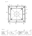
- Fig. 3A shows in front elevation a target device according to a first embodiment of the present invention
- Fig. 3B shows in block form a circuit arrangement of the target device according to the first embodiment.
- the target device has a front surface on which target plate 4 is mounted, the front surface facing a shooting spot where a shooter is positioned.
- the front surface of the target device shown in Fig. 3A is of a square shape having a vertical dimension of 10 cm and a horizontal dimension of 10 cm.
- Target plate 4 which is also of a square shape is mounted on a central area of the front surface of the target device.
- Target plate 4 comprises a solid panel and has a plurality of circular score areas as shown in Fig. 2 around its center.
- Target plate 4 is fastened to a casing of the target device by four screws 5 at its corners.
- the target device has LED group 8 comprising eight light-emitting elements, i.e., light-emitting diodes (LEDs) 8 1 through 8 8 , disposed around target plate 4.
- LEDs 8 1 through 8 8 are spaced at substantially equal in tervals around target plate 4. Specifically, LEDs 8 1 through 8 8 are positioned such that each of straight H lines (indicated by the dot-and-dash lines in FIG. 3A) extending from the center of target plate 4 to respective LEDs 8 1 through 8 8 is angularly spaced 45° from other adjacent straight lines.
- the target device also has impact position detector 11, score calculator 12A, and light-emitting element energizing unit 13A.
- the target device displays a score with LED group 8.
- Impact position detector 11 detects impact position (x, y) on target plate 4 according to the equations (1), (2) described above.
- Score calculator 12A calculates the distance from center O of target plate 4 to impact position (x, y) based on detected impact position (x, y), and compares the calculated distance with the ranges (radii) of the score areas to calculate a score for detected impact position (x, y). It is necessary that center O of target plate 4 and the detecting origin of impact position detector 11 be in complete alignment with each other.
- Light-emitting element energizing unit 13A determines an energizing pattern of LEDs 8 1 through 8 8 of LED group 8 depending on the score which has been calculated by score calculator 12A. For example, if the score calculated by score calculator 12A is "1", then light-emitting element energizing unit 13A energizes only LED 8 1 . If score calculator 12A has calculated scores "2" through “8", then light-emitting element energizing unit 13A energizes only LEDs 8 2 through 8 8 , respectively. Thus, an LED or LEDs corresponding to a score calculated by score calculator 12A are energized.
- the shooter can immediately recognize that the shot has won a score "5". If score calculator 12 has calculated a score "9", then light-emitting element energizing unit 13A energizes LED 8 2 and LED 8 7 . If score calculator 12 has calculated a score "10”, then light-emitting element energizing unit 13A energizes all LED 8 1 through LED 8 8 . Stated otherwise, the target device changes combinations of LEDs to be energized depending on the score which has been calculated by score calculator 12A. Usually, at least 10 LEDs would be required to display scores "0" through “10". According to the present embodiment, however, since some scores are expressed by changing combinations of LEDs to be energized, the number of LEDs that are required may be reduced from 10 to 8.
- the LEDs are energized progressively counterclockwise from the left lowermost one below target plate 4 in Fig. 3A as the score increases.
- the LEDs may be energized progressively clockwise.
- the number of LEDs that are used may further be reduced by using a binary representation of scores.
- the LEDs may be energized in any energizing patterns insofar as they allow the shooter to read scores which it has won.
- target plate 4 comprises a solid panel in the present embodiment, it may comprise a sheet of film or paper.
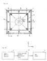
- Fig. 4A shows in front elevation the target device according to a second embodiment which does not form part of the present invention
- Fig. 4B shows in block form a circuit arrangement of the target device according to the second embodiment.
- the target device has LED group 9 comprising eight LEDs 9 1 through 9 8 disposed around target plate 4.
- eight LEDs 9 1 through 9 8 of LED group 9 are used to give an approximate indication of an impact position on target plate 4, rather than to indicate a score.
- the target device also has impact position detector 11 and light-emitting element energizing unit 13B.
- Light-emitting element energizing unit 13B energizes LED group 9 depending on an impact position on target plate 4. It is now assumed that the impact position on target plate 4 is represented by point A in Fig. 4A. Position (x, y) of point A is calculated according to the equations (1), (2) described above.
- Line segment OA extends from center O of target plate 4 to point A.
- Point A is positioned between line segment OB extending from center O to LED 9 4 and line segment OC extending from center O to LED 9 5 .
- Angle ⁇ 1 formed between line segments OA, OB is smaller than angle ⁇ 2 formed between line segments OA, OC.
- Light-emitting element energizing unit 13B energizes LED 9 4 on line segment OB.
- light-emitting element energizing unit 13B energizes an LED of all LEDs 9 1 through 9 8 of LED group 9, such that the angle formed between a line segment extending from center O to that LED and a line segment extending from center O to the impact position is minimum.
- the score areas on target plate 4 are divided into eight angular zones having equal angles (45°) around center O by eight LEDs 9 1 through 9 8 disposed at equal angles around target plate 4, and light-emitting element energizing unit 13B determines which one of the divided angular zones the impact position is located in, and energizes an LED belonging to the determined angular zone.
- the shooter can confirm from the shooting spot in which direction the impact position deviates from center O.
- most impact positions concentrate on score areas representing scores "7" through “10", i.e., score areas near center O. Therefore, the direction in which the impact position deviates from center O presents more important information than the distance by which the impact position deviates from center O for the shooter to correct its shooting action.
- the target device displays that deviating direction to give the shooter an indication of the deviating direction of the impact position. The shooter confirms the displayed deviating direction, and corrects its shooting action based on the confirmed deviating direction.
- an LED, of all LEDs 9 1 through 9 8 of LED group 9, which is linearly closest to point A of the impact position may be energized to present an approximate indication of the impact position to the shooter.
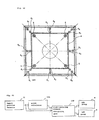
- Fig. 5A shows in front elevation the target device according to a third embodiment which does not form part of the present invention
- Fig. 5B shows in block form a circuit arrangement of the target device according to the third embodiment.
- the target device according to the third embodiment has LED group 9 of eight LEDs 9 1 through 9 8 disposed around target plate 4 as with the second embodiment.
- the target device according to the third embodiment also has impact position detector 11 and light-emitting element energizing unit 13C.
- Point A is positioned between line segment OB extending from center O to LED 9 4 and line segment OC extending from center O to LED 9 5 .
- Angle ⁇ 1 formed between line segments OA, OB is smaller than angle ⁇ 2 formed between line segments OA, OC.
- light-emitting element energizing unit 13C also energizes LED 9 4 on line segment OB as with the target device according to the second embodiment.
- light-emitting element energizing unit 13C determines an LED (first light-emitting element, i.e., LED 9 4 in FIG.
- LEDs 9 1 through 9 8 of LED group 9 such that the angle formed between a line segment extending from center O to that LED and line segment OA extending from center O to the impact position (point A) is smallest (first angle, i.e., ⁇ 1 in FIG. 5A), and an LED (second light-emitting element, i.e., LED 9 5 in FIG. 5A) such that the angle formed between a line segment extending from center O to that LED and line segment OA is next smallest (second angle, i.e., ⁇ 2 in FIG. 5A).
- light-emitting element energizing unit 13C energizes the first light-emitting element (LED 9 4 ), and also energizes the second light-emitting element (LED 9 5 ) if the difference between the first angle and the second angle is at most a predetermined angle
- the score areas on target plate 4 can be divided into 16 angular zones having equal angles (22.5°) around center O.
- the resolution with which to indicate the direction of the impact position with respect to the center of target plate 4 can be twice the resolution of the target device according to the second embodiment, i.e., can be represented by the 16 angular zones.
- the target device can display impact positions with simple energizing patterns of LED group 9. Since such simple energizing patterns of LED group 9 can visually be perceived from a distant location, the shooter positioned far from the target is able to easily recognize the impact position without the need for a display device for displaying an image of the target in the vicinity of the shooting spot where the shooter is positioned.
- Fig. 6A shows in front elevation the target device according to a fourth embodiment which forms part of the present invention
- Fig. 6B shows in block form a circuit arrangement of the target device according to the fourth embodiment.
- the target device according to the fourth embodiment has LED group 8 (first light-emitting element group) of eight LEDs 8 1 through 8 8 and LED group 9 (second light-emitting element group) of eight LEDs 9 1 through 9 8 which are disposed around target plate 4.
- the target device also has impact position detector 11, score calculator 12A, and light-emitting element energizing unit 13D.
- LED group 8 serves to display a score calculated by score calculator 12A
- LED group 9 serves to display an impact position detected by impact position detector 11.
- Both LED groups 8, 9 are energized by light-emitting element energizing unit 13d.
- LEDs 8 1 through 8 8 and LEDs 9 1 through 9 8 are positioned such that each of straight lines (indicated by the dot-and-dash lines in FIG. 6A) extending from the center of target plate 4 to respective LEDs 8 1 through 8 8 and respective LEDs 9 1 through 9 8 is angularly spaced 45° from other adjacent straight lines.
- LED group 9 is disposed outwardly of LED group 8.
- LED groups 8, 9 are not limited to the layout shown in FIG. 6A, but LED group 8 may be disposed outwardly of LED group 9.
- LED group 8 and LED group 9 emit light in different colors.
- LEDs 8 1 through 8 8 of LED group 8 comprise red light-emitting diodes
- LEDs 9 1 through 9 8 of LED group 9 comprise green light-emitting diodes.
- LED group 8 for displaying scores are energized in the same energizing patterns as with the first embodiment, and LED group 9 for displaying impact positions are energized in the same energizing patterns as with the second and third embodiments.
- Fig. 7A shows in front elevation the target device according to a fifth embodiment which forms part of the present invention
- Fig. 7B shows in block form a circuit arrangement of the target device according to the fifth embodiment.
- the target device according to the fifth embodiment has LED group 19 of eight LEDs 19 1 through 19 8 which can be energized in energizing patterns that are changed depending on a score calculated by score calculator 12A and can also be energized in energizing patterns that are changed depending on an impact position detected by impact position detector 11.
- the target device also has impact position detector 11, score calculator 12A, and light-emitting element energizing unit 13E.
- Light-emitting element energizing unit 13E energizes LED group 19 to display a score and an impact position in a time-division manner, or preferably alternately in an intermittent fashion.
- Each of LEDs 19 1 through 19 8 of LED group 19 comprises a bicolor LED for emitting color selectively in two colors. If each of LEDs 19 1 through 19 8 is a bicolor LED for emitting color selectively in red and green, then light-emitting element energizing unit 13E controls LEDs 19 1 through 19 8 to emit light in red for displaying scores and to emit light in green for displaying impact positions. Since LED group 19 emits light in different colors for displaying scores and impact positions, the shooter can easily distinguish score displays and impact position displays from each other.
- LED group 19 are energized in the same energizing patterns as with the first embodiment for displaying scores, and LED group 19 are energized in the same energizing patterns as with the second and third embodiments for displaying impact positions.
- the number of LEDs used may be smaller than the number of LEDs used in the fourth embodiment. Therefore, the target device according to the fifth embodiment is relatively low in cost and small in size.
- Fig. 8A shows in front elevation the target device according to a sixth embodiment which forms part of the present invention
- Fig. 8B shows in block form a circuit arrangement of the target device according to the sixth embodiment.
- the target device according to the sixth embodiment has LED group 8 of eight LEDs 8 1 through 8 8 as with the target device according to the first embodiment.
- at least one of LEDs 8 1 through 8 8 e.g., LEDs 8 1 through 8 3 is used as a ready lamp for indicating that the shooter can shoot a light beam
- at least one of LEDs 8 1 through 8 8 e.g., LEDs 8 5 through 8 7 is used as a busy lamp for indicating that the shooter cannot shoot a light beam.
- LEDs 8 1 through 8 3 which double as the ready lamp, are positioned below target plate 4. Therefore, when the shooter holds the laser gun and aims at target plate 4, LEDs 8 1 through 8 3 are concealed from the vision of the shooter by the gunbarrel, and hence the ready lamp does not obstruct the shooting action of the shooter.
- LEDs 8 5 through 8 7 which double as the busy lamp, are positioned above target plate 4. Therefore, when the shooter holds the laser gun and aims at target plate 4, LEDs 8 5 through 8 7 are present in the vision of the shooter, allowing the shooter to easily recognize that the shooter cannot shoot a light beam.
- the target device also has impact position detector 11, score calculator 12, and light-emitting element energizing unit 13F.
- Light-emitting element energizing unit 13F operates LED group 8 selectively as the ready lamp or the busy lamp in response to a signal from an external source.
- LEDs 8 1 through 8 8 of LED group 8 double as the ready lamp and the busy lamp, no separate ready lamp and busy lamp need to be provided, and hence the number of LEDs used may be reduced.
- the LED group or groups may be operated as a ready lamp and a busy lamp.
- Fig. 9A shows in perspective the target device according to a seventh embodiment which forms part of the present invention
- Fig. 9B shows in block form a circuit arrangement of the target device according to the seventh embodiment.
- Target plates which are spaced at different distances from laser gun (not shown in FIG. 9A), e.g., target plate 4 (spaced 10 m from laser gun) and target plate 4' (spaced 25 m from laser gun) shown in Fig. 1, have differently sized score areas. Even when an impact position remains the same on the different target plates, it is necessary for a score calculator to use a score calculating equation depending on the score areas of the target plate that is actually mounted on the target device.
- the target device according to the seventh embodiment has target plate setting switch 10 which can be operated by the user for setting the type of the target plate that is actually mounted on the target device.
- the target device also has target plate setting switch 10, impact position detector 11, score calculator 12B, and light-emitting element energizing unit 13A.
- target plate setting switch 10 impact position detector 11
- score calculator 12B score calculator 12B
- light-emitting element energizing unit 13A determines a score calculating equation for determining a score from an impact position on the target plate, and calculates a score according to the determined equation. Therefore, the target device can display an accurate score depending on the type of the target plate that is actually mounted on the target device.
- Target plate setting switch 10 may be incorporated in the target devices according to the fourth through sixth embodiments.
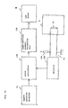
- Fig. 10 shows in block form a circuit arrangement of the target device according to an eighth embodiment which forms part of the present invention.
- the target device according to the eighth embodiment has target plate detector 14 for automatically detecting the type of the target plate that is actually mounted on the target device, in addition to impact position detector 11, score calculator 12B, and light-emitting element energizing unit 13A.
- Target plate detector 14 comprises pull-up resistor 14a and detector 14b.
- Resistor 15 which is embedded in the target plate is electrically connected to detector 14b.
- Detector 14b has its one terminal connected to pull-up resistor 14a and its other terminal connected to ground.
- Resistor 15 has a resistance which varies depending on the type of the target plate used, e.g., target plate 4 or target plate 4'.
- resistor 15 embedded in target plate 4 has its ends electrically connected to detector 14b, which reads the resistance of resistor 15, detects the type of mounted target plate 4, and provides outputs of the detected type to score calculator 12B.
- score calculator 12B After being supplied with the detected type from detector 14b, score calculator 12B applies an impact position on target plate 4 as detected by impact position detector 11 to the score calculating equation depending on the detected type, calculates a score according to the score calculating equation, and supplies the calculated score to light-emitting element energizing unit 13A.
- the score is displayed in the manner described above in the first embodiment.
- the eighth embodiment since the score calculating equation used in score calculator 12B is automatically changed depending on the type of the target plate used, the user finds it less burdensome to change the target plate than with the seventh embodiment, and any errors involved in setting the type of the target plate used are eliminated.
- the type of the target plate used is detected based on the resistance of resistor 15 embedded in the target plate.
- the type of the target plate used may be detected by reading information stored in an IC chip embedded in the target plate, magnetic information embedded in the target plate, or a pattern of slits disposed in the target plate.
- Target plate detector 14 may be incorporated in the target devices according to the fourth through sixth embodiments.
- FIG. 11A shows in perspective the target device accordinging to a ninth embodiment which forms part of the present invention
- FIG. 11B shows in block form a circuit arrangement of the target device according to the ninth embodiment.
- the target device supports square target plate 4 centrally on its front surface, target plate 4 having circular score areas as shown in Fig. 2 around its center.
- Target plate 4 is fastened to a casing of the target device by four screws 5 at its corners.
- Target device has speaker 18 mounted on a side wall of a casing thereof for producing speech or an electronic sound representative of an impact position and a score based on the impact position when a light beam shot from the laser gun (not shown in FIG. 11A) hits target plate 4.
- Speaker 18 may be mounted on any regions of target device where target plate 4 is not mounted, rather than a side wall of the casing thereof.
- the target device also has impact position detector 11, score calculator 12A, and sound output controller 17.
- impact position detector 11 detects an impact position on target plate 4 at the time a light beam shot from the laser gun hits target plate 4
- sound output controller 17 controls speaker 18 to output an electronic sound indicating that the light beam shot from the laser gun hits target plate 4.
- the sound that is produced when a bullet is shot from the gun is much louder than the sound that is produced when the bullet actually hits the target.
- the shooter can have a feel similar to a gun shooting action using a real bullet if an electronic sound simulating a real bullet shot is output from speaker 18 at the time the light beam emitted from the laser gun hits target plate 4.
- Impact position detector 11 detects an impact position of the light beam emitted from the laser gun as with the above embodiments.
- Score calculator 12A also calculates a score based on the impact position detected by impact position detector 11 as with the above embodiments.
- Information representing the score calculated by score calculator 12A is sent to sound output controller 17, which controls speaker 18 to output a sound representing the score based on the score calculated by score calculator 12A.
- the calculated score may be output as speech information from speaker 18. If the score is equal to or higher than a predetermined score, then speech information or a melody indicating that the score is equal to or higher than the predetermined score may be output from speaker 18. Upon hearing such a sound, the shooter can obtain an auditory recognition of the score of the shot.
- sound information is output from speaker 4 based on impact positions on target plate 4 and scores depending on the impact positions.
- the visual display system for displaying impact positions and scores with LEDs according to any of the above embodiments may be combined with the system according to the ninth embodiment for producing an auditory presentation of impact positions and scores.
Landscapes
- Engineering & Computer Science (AREA)
- General Engineering & Computer Science (AREA)
- Aiming, Guidance, Guns With A Light Source, Armor, Camouflage, And Targets (AREA)
Claims (19)
- Zielvorrichtung mit:einer Zielscheibe (4);einer Gruppe (8) lichtemittierender Elemente, die nahe der Zielscheibe (4) angeordnet ist;einer Auftreffpositionsdetektionseinrichtung (11) zur Detektion einer Auftreffposition auf die Zielscheibe (4); einer Punktezahlberechnungseinrichtung (12) zur Berechnung einer Punktezahl beruhend auf der Auftreffposition, die durch die Auftreffpositionsdetektionseinrichtung (11) detektiert wird; undeiner Ansteuereinrichtung (13) der Gruppe lichtemittierender Elemente zum Einschalten der Gruppe (8) lichtemittierender Elemente abhängig von der berechneten Punktezahl,wobei die Gruppe (8) lichtemittierender Elemente mehrere lichtemittierende Elemente (81-88) aufweist, die an im wesentlichen gleich beabstandeten Intervallen um die Zielscheibe angeordnet sind,
dadurch gekennzeichnet, daß die Ansteuereinrichtung (13) der Gruppe lichtemittierender Elemente eine Einrichtung aufweist, um Einschaltmuster der lichtemittierenden Elemente (81-88) abhängig von der Punktezahl zu ändern, die durch die Punktezahlberechnungseinrichtung (12) berechnet wird. - Zielvorrichtung nach Anspruch 1, die ferner eine zweite Gruppe (9) lichtemittierender Elemente aufweist, die in Einschaltmustern einschaltbar sind, die abhängig von der Auftreffposition variieren, die durch die Auftreffpositionsdetektionseinrichtung (11) detektiert wird.
- Zielvorrichtung nach Anspruch 2, wobei die Gruppe (8) lichtemittierender Elemente und die zweite Gruppe (9) lichtemittierender Elemente einschaltbar sind, um jeweils Licht in unterschiedlichen Farben zu emittieren.
- Zielvorrichtung nach einem der Ansprüche 1 bis 3, wobei die Ansteuereinrichtung (13) der Gruppe lichtemittierender Elemente eine Einrichtung zum Einschalten der Gruppe lichtemittierender Elemente aufweist, um die Punktezahl und die Auftreffposition in einer Zeitunterteilungsweise anzuzeigen.
- Zielvorrichtung nach Anspruch 4, wobei die Gruppe (8) lichtemittierender Elemente und die zweite Gruppe (9) lichtemittierender Elemente abwechselnd in einer intermittierenden Weise eingeschaltet werden.
- Zielvorrichtung nach Anspruch 1, wobei die Gruppe (8) lichtemittierender Elemente mehrere lichtemittierende Elemente (81-88) aufweist, wobei jedes der lichtemittierenden Elemente (81-88) eine zweifarbige lichtemittierende Diode zur Emission von Licht in zwei Farben aufweist.
- Zielvorrichtung nach Anspruch 6, wobei die Ansteuereinrichtung (13) der Gruppe lichtemittierender Elemente eine Einrichtung zum Einschalten der lichtemittierenden Elemente (81-88) aufweist, um die Punktezahl und die Auftreffposition in unterschiedlichen Farben anzuzeigen.
- Zielvorrichtung nach einem der Ansprüche 1 bis 7, wobei die Gruppe (8) lichtemittierender Elemente mehrere lichtemittierende Elemente (81-88) aufweist, wobei mindestens eines der lichtemittierenden Elemente als eine Bereitschaftslampe zur Anzeige betriebsfähig ist, daß ein Schütze auf die Zielscheibe (4) schießen kann.
- Zielvorrichtung nach Anspruch 8, wobei das mindestens eine der lichtemittierenden Elemente, das als die Bereitschaftslampe betriebsfähig ist, unter der Zielscheibe (4) angeordnet ist.
- Zielvorrichtung nach einem der Ansprüche 1 bis 9, wobei die Gruppe (8) lichtemittierender Elemente mehrere lichtemittierende Elemente (81-88) aufweist, wobei mindestens eines der lichtemittierenden Elemente als eine Besetztlampe zur Anzeige betriebsfähig ist, daß ein Schütze nicht auf die Zielscheibe (4) schießen kann.
- Zielvorrichtung nach Anspruch 10, wobei das mindestens eine der lichtemittierenden Elemente, das als die Besetztlampe betriebsfähig ist, über der Zielscheibe (4) angeordnet ist.
- Zielvorrichtung nach einem der Ansprüche 1 bis 11, die ferner aufweist:einen Schalter (10) zur Einstellung eines Typs der Zielscheibe (4), die an Ort und Stelle angebracht ist.
- Zielvorrichtung nach Anspruch 12, wobei die Punktezahlberechnungseinrichtung (12) eine Einrichtung aufweist, um eine Gleichung zur Berechnung der Punktezahl aus der Auftreffposition abhängig vom Typ der Zielscheibe (4) zu ändern, der durch den Schalter (10) eingestellt wird.
- Zielvorrichtung nach einem der Ansprüche 1 bis 13, die ferner aufweist:eine Detektionseinrichtung (14) zur automatischen Detektion eines Typs der Zielscheibe (4), die an Ort und Stelle angebracht ist.
- Zielvorrichtung nach Anspruch 14, wobei die Punktezahlberechnungseinrichtung (12) eine Einrichtung aufweist, um eine Gleichung zur Berechnung der Punktezahl aus der Auftreffposition abhängig vom Typ der Zielscheibe (4) zu ändern, der durch die Detektionseinrichtung (14) automatisch detektiert wird.
- Zielvorrichtung nach Anspruch 14 oder 15, wobei die Detektionseinrichtung (4) eine Einrichtung zur Detektion des Typs der Zielscheibe (4), die an Ort und Stelle angebracht ist, durch Messung des Widerstandswerts eines Widerstands aufweist, der in die Zielscheibe (4) eingebaut ist, die an Ort und Stelle angebracht ist.
- Zielvorrichtung nach Anspruch 14, 15 oder 16, wobei die Detektionseinrichtung (14) eine Einrichtung zur Detektion des Typs der Zielscheibe (4), die an Ort und Stelle angebracht ist, durch Messung von Informationen aufweist, die in einem IC-Chip gespeichert sind, der in der Zielscheibe (4) eingebaut ist, die an Ort und Stelle angebracht ist.
- Zielvorrichtung nach Anspruch 14, 15, 16 oder 17, wobei die Detektionseinrichtung (14) eine Einrichtung zur Detektion des Typs der Zielscheibe (4), die an Ort und Stelle angebracht ist, durch Messung magnetischer Informationen aufweist, die in der Zielscheibe (4) eingebaut sind, die an Ort und Stelle angebracht ist.
- Zielvorrichtung nach einem der Ansprüche 14 bis 18, wobei die Detektionseinrichtung (14) eine Einrichtung zur Detektion des Typs der Zielscheibe (4), die an Ort und Stelle angebracht ist, durch Messung eines Musters von Schlitzen aufweist, die in der Zielscheibe (4) angeordnet sind, die an Ort und Stelle angebracht ist.
Applications Claiming Priority (4)
| Application Number | Priority Date | Filing Date | Title |
|---|---|---|---|
| JP2002058775 | 2002-03-05 | ||
| JP2002058775 | 2002-03-05 | ||
| JP2002119050A JP3616608B2 (ja) | 2002-03-05 | 2002-04-22 | 標的装置 |
| JP2002119050 | 2002-04-22 |
Publications (2)
| Publication Number | Publication Date |
|---|---|
| EP1342979A1 EP1342979A1 (de) | 2003-09-10 |
| EP1342979B1 true EP1342979B1 (de) | 2006-09-27 |
Family
ID=27759727
Family Applications (1)
| Application Number | Title | Priority Date | Filing Date |
|---|---|---|---|
| EP03004329A Expired - Lifetime EP1342979B1 (de) | 2002-03-05 | 2003-02-28 | System zum Anzeigen und Sichtbarmachen von Treffern |
Country Status (7)
| Country | Link |
|---|---|
| US (1) | US20030171150A1 (de) |
| EP (1) | EP1342979B1 (de) |
| JP (1) | JP3616608B2 (de) |
| KR (1) | KR20030074228A (de) |
| AU (1) | AU2003200795A1 (de) |
| DE (1) | DE60308573T2 (de) |
| SG (1) | SG150372A1 (de) |
Families Citing this family (18)
| Publication number | Priority date | Publication date | Assignee | Title |
|---|---|---|---|---|
| KR100617889B1 (ko) * | 2004-11-24 | 2006-09-08 | 이종원 | 광선총을 이용한 사격시스템 |
| US9793247B2 (en) | 2005-01-10 | 2017-10-17 | Cree, Inc. | Solid state lighting component |
| US9070850B2 (en) | 2007-10-31 | 2015-06-30 | Cree, Inc. | Light emitting diode package and method for fabricating same |
| US7821023B2 (en) | 2005-01-10 | 2010-10-26 | Cree, Inc. | Solid state lighting component |
| US20070238534A1 (en) * | 2006-03-28 | 2007-10-11 | Avraham Pollack | Target game |
| US9335006B2 (en) | 2006-04-18 | 2016-05-10 | Cree, Inc. | Saturated yellow phosphor converted LED and blue converted red LED |
| US10295147B2 (en) * | 2006-11-09 | 2019-05-21 | Cree, Inc. | LED array and method for fabricating same |
| US9425172B2 (en) | 2008-10-24 | 2016-08-23 | Cree, Inc. | Light emitter array |
| US9786811B2 (en) | 2011-02-04 | 2017-10-10 | Cree, Inc. | Tilted emission LED array |
| US10842016B2 (en) | 2011-07-06 | 2020-11-17 | Cree, Inc. | Compact optically efficient solid state light source with integrated thermal management |
| DE102012015622A1 (de) * | 2012-08-07 | 2014-02-13 | Rainer Mahlstedt | Schießziel mit optischer Trefferanzeige |
| KR101280093B1 (ko) * | 2012-10-17 | 2013-06-28 | 박찬일 | 피격 재현을 위한 시스템, 이를 위한 장치 및 이를 위한 방법 |
| US9448043B2 (en) * | 2014-02-28 | 2016-09-20 | Roberts Tactical Precision, Inc. | Interactive target and system for long range shooting |
| US20160216084A1 (en) * | 2015-01-22 | 2016-07-28 | Robert Louis Foege | Laser Light Activated Target |
| US20190137227A1 (en) * | 2017-06-29 | 2019-05-09 | Michael Anthony Sloan | Glow in the dark dartboard, darts, tips, shafts, flights and the manufacturing of same |
| US11293725B2 (en) * | 2017-07-11 | 2022-04-05 | Advanced Target Technologies Ip Holdings Inc. | Method, system and apparatus for illuminating targets using fixed, disposable, self-healing reflective light diffusion systems |
| CN111609764A (zh) * | 2020-05-26 | 2020-09-01 | 珠海光格信息技术有限公司 | 速射光电靶及其工作方法 |
| US12553916B1 (en) | 2024-07-24 | 2026-02-17 | Daniel Loikits | System for measuring skew and speed of an arrow |
Family Cites Families (18)
| Publication number | Priority date | Publication date | Assignee | Title |
|---|---|---|---|---|
| DE2523362C2 (de) * | 1975-05-27 | 1985-04-18 | Witzig, geb. Geßmann, Hilde, 8900 Augsburg | Elektronischer Schieß-Simulator |
| CH623652A5 (en) * | 1977-05-27 | 1981-06-15 | Laspo Ag | System for simulated firing |
| US4708341A (en) * | 1984-02-29 | 1987-11-24 | Indoor Archery International Corporation | Archery/practice exercise device and attachments therefor |
| CH675909A5 (en) * | 1988-04-18 | 1990-11-15 | Bernardini Carlo De | Laser beam target for weapon sighting - comprises array of sensors with digital indicator showing position at which beam strikes array |
| DE4002126C2 (de) * | 1990-01-25 | 2001-02-08 | Nsm Ag | Wurfpfeil-Spielgerät |
| US5193817A (en) * | 1991-12-24 | 1993-03-16 | Francis Pan | Dart game |
| US5358253A (en) * | 1992-11-24 | 1994-10-25 | Chen Sheng Kun | Light and sound emittable dartsboard |
| GB9315904D0 (en) * | 1993-07-31 | 1993-09-15 | Allen John | Missile detection and location |
| CN1064127C (zh) * | 1995-06-02 | 2001-04-04 | 黄椿木 | 以数字显示器显示板球游戏结果的电子标靶装置 |
| US5755443A (en) * | 1996-07-10 | 1998-05-26 | Huang; Chun-Mu | Dart game controller that adjusts one score to effect other scores |
| US6109614A (en) * | 1996-07-19 | 2000-08-29 | Tardis Systems, Inc. | Remote sensing apparatus of supersonic projectile |
| US5743534A (en) * | 1996-10-28 | 1998-04-28 | Pan; John C. | Darts target with target indication and electrical scoring |
| JP3206899B2 (ja) * | 1998-11-18 | 2001-09-10 | コナミ株式会社 | 発光表示装置、発光表示装置を用いた標的ゲーム装置、標的命中表示方法 |
| JP2004537701A (ja) * | 2000-01-13 | 2004-12-16 | ビームヒット,リミティド ライアビリティー カンパニー | 発火チェンバに配置するように構成されたレーザー送信装置及び火器動作をシミュレートする方法 |
| AU2001263353B2 (en) * | 2000-05-19 | 2007-03-01 | L-3 Communications Corporation | Firearm laser training system and method employing an actuable target assembly |
| JP2003536045A (ja) * | 2000-06-09 | 2003-12-02 | ビームヒット,リミティド ライアビリティー カンパニー | 多種類ターゲットとシミュレートされた発射物衝突位置の視覚フィードバックを有する、小火器訓練を行う為のレーザー小火器訓練システム及び方法 |
| US7258344B2 (en) * | 2003-01-16 | 2007-08-21 | Dmi Sports, Inc. | Electronically-scored game providing audible feedback and method of use |
| US20050006847A1 (en) * | 2003-07-10 | 2005-01-13 | Ross Thomas A. | Dart game |
-
2002
- 2002-04-22 JP JP2002119050A patent/JP3616608B2/ja not_active Expired - Fee Related
-
2003
- 2003-02-28 DE DE60308573T patent/DE60308573T2/de not_active Expired - Lifetime
- 2003-02-28 EP EP03004329A patent/EP1342979B1/de not_active Expired - Lifetime
- 2003-03-03 US US10/376,457 patent/US20030171150A1/en not_active Abandoned
- 2003-03-03 AU AU2003200795A patent/AU2003200795A1/en not_active Abandoned
- 2003-03-04 SG SG200301354-7A patent/SG150372A1/en unknown
- 2003-03-05 KR KR10-2003-0013690A patent/KR20030074228A/ko not_active Ceased
Also Published As
| Publication number | Publication date |
|---|---|
| AU2003200795A1 (en) | 2003-09-25 |
| DE60308573T2 (de) | 2007-01-18 |
| SG150372A1 (en) | 2009-03-30 |
| US20030171150A1 (en) | 2003-09-11 |
| KR20030074228A (ko) | 2003-09-19 |
| EP1342979A1 (de) | 2003-09-10 |
| JP3616608B2 (ja) | 2005-02-02 |
| JP2003329398A (ja) | 2003-11-19 |
| DE60308573D1 (de) | 2006-11-09 |
Similar Documents
| Publication | Publication Date | Title |
|---|---|---|
| EP1342979B1 (de) | System zum Anzeigen und Sichtbarmachen von Treffern | |
| US6962532B2 (en) | Laser gun and shooting system for the same | |
| US8888491B2 (en) | Optical recognition system and method for simulated shooting | |
| US8678824B2 (en) | Shooting simulation system and method using an optical recognition system | |
| US6473980B2 (en) | Infrared laser transmitter alignment verifier and targeting system | |
| KR101594023B1 (ko) | 레이저 광 사격 시스템 | |
| US20100178967A1 (en) | Shooting game processing method | |
| JP3653021B2 (ja) | 光銃の射撃システム、その信号処理方法、及び、標的装置の位置調整方法 | |
| KR20110007891A (ko) | 정확한 명중 부위 인식이 가능한 사격훈련시스템 | |
| KR101142136B1 (ko) | 다트 게임 장치 | |
| KR20030069095A (ko) | 지도자가 경기자에게 실시간으로 표본을 나타내도록 하는장치를 갖는 사격 훈련 시스템 | |
| KR102502774B1 (ko) | 가상 골프 시스템 | |
| KR100626253B1 (ko) | 전자 경기 시스템, 전자 경기 방법, 서버 및 컴퓨터프로그램 | |
| WO2019026855A1 (ja) | ダーツゲーム装置及びプログラム | |
| EP1614988B1 (de) | Bull's-Eye-Zieleinrichtung | |
| JP2004333122A (ja) | 標的装置 | |
| JP4009637B2 (ja) | 光銃の射撃システム | |
| SE526619C2 (sv) | Målskytteanordning för att visa träffpunkten för en optisk kula mot en måltavla | |
| CN217163159U (zh) | 一种棋类对弈系统 | |
| JP2003294394A (ja) | 小火器射撃評価システム | |
| JP3902624B2 (ja) | 光銃 | |
| KR102098290B1 (ko) | 양궁의 전자 표적 시스템 및 그 제어 방법 | |
| JP4203769B2 (ja) | 着弾点の表示装置、および射撃システム | |
| JP2025141638A (ja) | 射撃ゲームシステムおよび娯楽施設 | |
| KR101733266B1 (ko) | 체감형 게임 제공 시스템 및 그 방법과 이를 위한 센싱 장치 |
Legal Events
| Date | Code | Title | Description |
|---|---|---|---|
| PUAI | Public reference made under article 153(3) epc to a published international application that has entered the european phase |
Free format text: ORIGINAL CODE: 0009012 |
|
| AK | Designated contracting states |
Kind code of ref document: A1 Designated state(s): AT BE BG CH CY CZ DE DK EE ES FI FR GB GR HU IE IT LI LU MC NL PT SE SI SK TR |
|
| AX | Request for extension of the european patent |
Extension state: AL LT LV MK RO |
|
| 17P | Request for examination filed |
Effective date: 20030723 |
|
| 17Q | First examination report despatched |
Effective date: 20031201 |
|
| AKX | Designation fees paid |
Designated state(s): DE FR GB SE |
|
| GRAP | Despatch of communication of intention to grant a patent |
Free format text: ORIGINAL CODE: EPIDOSNIGR1 |
|
| GRAS | Grant fee paid |
Free format text: ORIGINAL CODE: EPIDOSNIGR3 |
|
| GRAA | (expected) grant |
Free format text: ORIGINAL CODE: 0009210 |
|
| AK | Designated contracting states |
Kind code of ref document: B1 Designated state(s): DE FR GB SE |
|
| REG | Reference to a national code |
Ref country code: GB Ref legal event code: FG4D |
|
| REF | Corresponds to: |
Ref document number: 60308573 Country of ref document: DE Date of ref document: 20061109 Kind code of ref document: P |
|
| REG | Reference to a national code |
Ref country code: SE Ref legal event code: TRGR |
|
| PGFP | Annual fee paid to national office [announced via postgrant information from national office to epo] |
Ref country code: SE Payment date: 20061206 Year of fee payment: 5 |
|
| PGFP | Annual fee paid to national office [announced via postgrant information from national office to epo] |
Ref country code: GB Payment date: 20070228 Year of fee payment: 5 |
|
| ET | Fr: translation filed | ||
| PLBE | No opposition filed within time limit |
Free format text: ORIGINAL CODE: 0009261 |
|
| STAA | Information on the status of an ep patent application or granted ep patent |
Free format text: STATUS: NO OPPOSITION FILED WITHIN TIME LIMIT |
|
| 26N | No opposition filed |
Effective date: 20070628 |
|
| GBPC | Gb: european patent ceased through non-payment of renewal fee |
Effective date: 20080228 |
|
| EUG | Se: european patent has lapsed | ||
| PG25 | Lapsed in a contracting state [announced via postgrant information from national office to epo] |
Ref country code: SE Free format text: LAPSE BECAUSE OF NON-PAYMENT OF DUE FEES Effective date: 20080301 |
|
| PG25 | Lapsed in a contracting state [announced via postgrant information from national office to epo] |
Ref country code: GB Free format text: LAPSE BECAUSE OF NON-PAYMENT OF DUE FEES Effective date: 20080228 |
|
| REG | Reference to a national code |
Ref country code: DE Ref legal event code: R081 Ref document number: 60308573 Country of ref document: DE Owner name: NEC PERSONAL COMPUTERS, LTD., JP Free format text: FORMER OWNER: NEC CORP., TOKYO, JP Effective date: 20110929 Ref country code: DE Ref legal event code: R082 Ref document number: 60308573 Country of ref document: DE Representative=s name: VOSSIUS & PARTNER PATENTANWAELTE RECHTSANWAELT, DE Effective date: 20110929 Ref country code: DE Ref legal event code: R082 Ref document number: 60308573 Country of ref document: DE Representative=s name: VOSSIUS & PARTNER, DE Effective date: 20110929 |
|
| REG | Reference to a national code |
Ref country code: FR Ref legal event code: TP Owner name: NEC PERSONAL COMPUTERS, LTD, JP Effective date: 20111024 |
|
| PGFP | Annual fee paid to national office [announced via postgrant information from national office to epo] |
Ref country code: FR Payment date: 20140211 Year of fee payment: 12 |
|
| PGFP | Annual fee paid to national office [announced via postgrant information from national office to epo] |
Ref country code: DE Payment date: 20140417 Year of fee payment: 12 |
|
| REG | Reference to a national code |
Ref country code: DE Ref legal event code: R119 Ref document number: 60308573 Country of ref document: DE |
|
| REG | Reference to a national code |
Ref country code: FR Ref legal event code: ST Effective date: 20151030 |
|
| PG25 | Lapsed in a contracting state [announced via postgrant information from national office to epo] |
Ref country code: DE Free format text: LAPSE BECAUSE OF NON-PAYMENT OF DUE FEES Effective date: 20150901 |
|
| PG25 | Lapsed in a contracting state [announced via postgrant information from national office to epo] |
Ref country code: FR Free format text: LAPSE BECAUSE OF NON-PAYMENT OF DUE FEES Effective date: 20150302 |