EP1342962A1 - Speicherofen - Google Patents
Speicherofen Download PDFInfo
- Publication number
- EP1342962A1 EP1342962A1 EP03450021A EP03450021A EP1342962A1 EP 1342962 A1 EP1342962 A1 EP 1342962A1 EP 03450021 A EP03450021 A EP 03450021A EP 03450021 A EP03450021 A EP 03450021A EP 1342962 A1 EP1342962 A1 EP 1342962A1
- Authority
- EP
- European Patent Office
- Prior art keywords
- combustion chamber
- wall
- storage element
- storage
- oven according
- Prior art date
- Legal status (The legal status is an assumption and is not a legal conclusion. Google has not performed a legal analysis and makes no representation as to the accuracy of the status listed.)
- Granted
Links
Images

Classifications
-
- F—MECHANICAL ENGINEERING; LIGHTING; HEATING; WEAPONS; BLASTING
- F24—HEATING; RANGES; VENTILATING
- F24H—FLUID HEATERS, e.g. WATER OR AIR HEATERS, HAVING HEAT-GENERATING MEANS, e.g. HEAT PUMPS, IN GENERAL
- F24H7/00—Storage heaters, i.e. heaters in which the energy is stored as heat in masses for subsequent release
- F24H7/02—Storage heaters, i.e. heaters in which the energy is stored as heat in masses for subsequent release the released heat being conveyed to a transfer fluid
- F24H7/0275—Storage heaters, i.e. heaters in which the energy is stored as heat in masses for subsequent release the released heat being conveyed to a transfer fluid using solid fuel
- F24H7/0283—Storage heaters, i.e. heaters in which the energy is stored as heat in masses for subsequent release the released heat being conveyed to a transfer fluid using solid fuel the transfer fluid being air
Definitions
- the present invention relates to a furnace with an outer cladding, a combustion chamber, at least one storage element and a convection area between the combustion chamber and the outer cladding of the furnace.
- the Romanian document RO 11 67 46 B1 discloses a radiator construction in which fresh air is guided along the side wall of the combustion chamber. The heated fresh air streams are then led through openings, in particular in the upper section of the combustion chamber wall, into the combustion chamber, obviously in order to improve the combustion.
- a further development is known from DE 38 32 011 A1, in which a tiled stove with a thermo-bimetallic heating control is described.
- the tiled walls are detachably connected to the basic tiled stove housing, which are equipped with a thermo-bimetal perforated disc hollow body and a compression spring against the tiled wall.
- a thermo-bimetal perforated disc hollow body and a compression spring against the tiled wall.
- convective distances are created between the heating stove and the tiled walls, so that the tiled stove can act temporarily as a heat storage stove and sometimes as a convection stove.
- At least one storage element is then arranged on at least one outer wall of the combustion chamber, with room air to be heated flows in a convection gap provided between the storage element and the outer cladding of the furnace.
- the storage element which is advantageously characterized by very good thermal conductivity, quickly transports the heat energy released in the combustion chamber to its outside facing away from the combustion chamber, so that the heat energy can be released quickly to the air to be heated.
- the storage element is attached to the combustion chamber, preferably directly on the combustion chamber, as a result of which the accumulating heat can be absorbed by the storage element in the best possible way. It is advantageous if the storage element has a heat resistance of up to 1200 ° C. in order to ensure constant and error-free heat transport from the combustion chamber via the storage element to the air flowing through the convection gap.
- the storage element is attached to the outer wall of the firebox by means of holding devices.
- the storage elements can be held on the firebox in various ways, such as by clamping at the top and bottom of the storage element or by simple attachment, e.g. Screw connection, the storage elements directly to the outer wall of the combustion chamber.
- the storage elements can be attached to any shape of the firebox by means of variable holding devices.
- the storage elements are plate-shaped.
- Such a design has an extremely favorable effect on the heat transfer from the combustion chamber to the storage element, since a plate shape can lie flat on the outer wall of the combustion chamber - provided, of course, that the outer wall of the combustion chamber is also flat.
- the storage elements or the storage disks in Provide form of strips so that the surface of the outer wall of the firebox can be covered at least in some areas.
- the material of the storage element can be separated, preferably cut.
- the storage elements have a smooth surface on their side facing the combustion chamber and a rough, preferably corrugated surface on their side facing away from the combustion chamber and facing the convection gap.
- the storage elements or the storage plates can also have variable surfaces. It is also conceivable that the side of the storage element facing the combustion chamber has a curved surface. According to the invention, provision of recesses on the surface of the storage elements is also possible in some areas, either for the purpose of mounting the element on the outer wall of the combustion chamber or for providing air ducts in the convection gap.
- the storage elements preferably have a rough, preferably ribbed and / or corrugated surface on their side facing away from the combustion chamber.
- the shafts or ribs serve to maximize the surface of the storage element for the air flow in the convection area or to slow the air flow through forced deflections and thereby improve the heat exchange.
- the storage elements are made of a material which has a thermal conductivity of 4 to 9 W (mK) -1 and a specific heat capacity of 0.6 to 1 J g -1 K -1 . This enables an increase in the heat storage capacity and thus also a long-lasting heat transfer of the energy to the room air to be heated flowing past.
- magnetite storage elements are best suited for this purpose, although conventional heat storage materials can also be used.
- one or more outlet openings is or are provided on at least one side of the outer cladding of the furnace.
- a commercially available stove (model AUSTROFLAMM PUR, Austroflamm, AT) with the following dimensions and specifications: H / W / D 1258/450/429 mm Firebox H / W / T 270/325/350 mm Weight 160 kg Nominal heating output according to DIN 18891 6 kW Min / Max output in kW 3.5 / 8 kW Room heating output depending on the house insulation 60-120 m 3 was subjected to two test runs, one without storage elements (comparison) and one according to the invention with storage element attached to the outer wall of the combustion chamber (approx.
- the heat generated is primarily given off to the storage elements 2 attached to the side and above the combustion chamber 1.
- the storage elements 2 in turn heat the air present in the convection gap 3, which rises thereby and can escape into the surrounding space through openings 5 provided in the outer cladding 4. Fresh air is subsequently sucked in through the air inlet 6 and further into the convection gap 3.
- FIG. 1 A possible embodiment of a furnace according to the present invention is shown in FIG.
- the combustion chamber 1 is provided on the inside with a fire-resistant lining 7, 8 and is enclosed by a wall 9.
- the storage elements 2 directly adjoin the outer wall 9 of the combustion chamber 1, these in turn being enclosed by the outer cladding 4, a convection gap or space 3 remaining free between the outer cladding 4 and the storage element 2.
- the storage elements 2 heat the air present in the convection gap 3, which air thereby rises and through in the outer cladding 4 provided openings (not shown) can escape into the surrounding space. Fresh air is then sucked in through air inlets in the area near the floor (not shown) and further into the convection gap 3.
- the firebox 1 is in turn provided with a fireproof lining 7 and enclosed by a wall 9.
- the storage elements 2 directly adjoin the rear of the outer wall 9 of the combustion chamber 1, with recesses being provided on the side thereof facing the outer wall 9 of the combustion chamber 1.
- the storage elements are in turn enclosed by the outer cladding 4, a convection gap or space 3 remaining between the outer cladding 4 and the storage element 2.
- the storage elements 2 also heat the air present in the convection gap or space 3, which thereby rises and can escape into the surrounding space through openings (not shown) provided in the outer cladding 4. Fresh air is then sucked in through air inlets in the area near the floor (not shown) and further into the convection gap 3.
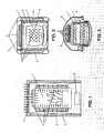
- FIGS. 4 and 5 The exact arrangement of the storage elements 2 within the furnaces according to FIGS. 2 and 3 can be seen from FIGS. 4 and 5. From FIG. 5 it can also be seen that, in addition to the storage elements 2 adjoining the rear of the outer wall 9 of the combustion chamber 1, the storage elements 2 surrounding the flue gas outlet are also provided in the furnace according to FIG.
Landscapes
- Engineering & Computer Science (AREA)
- Physics & Mathematics (AREA)
- Thermal Sciences (AREA)
- Chemical & Material Sciences (AREA)
- Combustion & Propulsion (AREA)
- Mechanical Engineering (AREA)
- General Engineering & Computer Science (AREA)
- Baking, Grill, Roasting (AREA)
- Furnace Housings, Linings, Walls, And Ceilings (AREA)
- Solid-Fuel Combustion (AREA)
Abstract
Description
- Die vorliegende Erfindung betrifft einen Ofen mit Außenverkleidung, einem Feuerraum, wenigstens einem Speicherelement und einem Konvektionsbereich zwischen Feuerraum und Außenverkleidung des Ofens.
- Traditionell hergestellte Speicheröfen, insbesondere Kachelöfen oder Kamine, benötigen eine relativ lange An- bzw. Aufheizphase, um die gewünschte Energie abgeben zu können. Das Grundprinzip nach welchen solche Speicherheizanlagen arbeiten, liegt in der Wärmespeicherung, welche durch das Material der Außenumwandung bewerkstelligt wird. Dieses Wärmespeichermaterial, zumeist aus Schamotte oder Ton hergestellt, reagiert äußerst träge in Bezug auf Wärmeaufnahme und die Wärmeverteilung innerhalb des Materials. Die Wärmeabstrahlung erfolgt dann über eine relativ große Oberfläche direkt an die Umgebung. Aufgrund dessen erweisen sich derartige Öfen als kaum regulierbar und benötigen zudem viel Raum.
- Weiters ist bekannt, dass moderne, industrielle Heizanlagen oder Feuerungseinrichtungen zwar eine sehr rasche Aufheizphase haben, man allerdings nicht unbedingt mit einer langen Nachheizphase nach Abschalten der Feuerung rechnen kann, da die eingesetzten Materialien solcher Heizanlagen für eine nachhaltige Wärmeabgabe gar nicht geschaffen sind. Derartige Öfen arbeiten nach dem Prinzip der Konvektion, wobei die Brennräume zumeist aus metallischem Material, wie Gusseisen oder Stahlblech, hergestellt sind und die zu erwärmenden Luft auf relativ kleinen Flächen aufgeheizt wird. Die erwärmte Luft steigt nach oben, um dann in den zu beheizenden Raum abgegeben zu werden und gleichzeitig neue, kalte Frischluft anzusaugen. Aufgrund der raschen Wirkungsweise derartiger Heizeinrichtungen eignen sie sich allerdings zumeist nur als Zusatzheizgeräte.
- In der rumänischen Schrift RO 11 67 46 B1 wird eine Heizkörperkonstruktion offenbart, bei welcher Frischluft entlang der Seitenwandung des Feuerraumes geführt wird. Die erwärmten Frischluftströme werden dann über Durchbrechungen, insbesondere im oberen Abschnitt der Feuerraumwandung, in den Feuerraum geführt, offensichtlich um die Verbrennung zu verbessern.
- In der letzten Zeit galt das Bestreben, eine Kombination der beiden oben genannten Prinzipien (Wärmestrahlung von Speicherelementen und Konvektion) zur Verfügung zu stellen, wobei insbesondere versucht wurde, ein wärmespeicherndes Material in mit Konvektionsluft arbeitenden Schnellheizanlagen einzusetzen.
- Ein Versuch dieses Konzept umzusetzen ist beispielsweise aus der DE 197 52 699 C1 bekannt. Dieses Dokument zeigt einen Heizofen mit Wärmespeicherplatten, welche zwischen einem blechummantelten Feuerraum und der Außenwandung bzw. Außenverkleidung des Ofens jeweils beabstandet angeordnet sind. Durch diese Abstände entstehen zwei parallel laufende Luft- bzw. Strömungskanäle, welche der Zirkulation von eingeschlossener Luft dienen. Zur Erreichung eines Luftkreislaufes sind Flächenspeicherkörper ober-halb und unterhalb des Feuerraumes beabstandet vorgesehen, sodass beim Aufwärtsströmen der aufgeheizten Luft ein Entweichen der Luft verhindert wird. Das Prinzip besteht dabei im Zirkulieren der Luft innerhalb des Ofens, es wird keine erwärmte Luft nach außen hin abgegeben.
- Eine Weiterentwicklung ist aus der DE 38 32 011 A1 bekannt, in welcher ein Kachelofen mit einer thermo-bimetallgesteuerter Heizregelung beschrieben ist. Die Kachelwände stehen in lösbarer Verbindung mit dem Kachelgrundofengehäuse, welche mit einem Thermo-bimetall-Lochscheiben-Hohlkörper und einer gegen die Kachelwand widergelagerten Druckfeder ausgestattet sind. Abhängig von der jeweiligen Temperatur im Thermo-bimetall-Lochscheiben-Hohlkörper werden zwischen dem Heizofen und den Kachelwänden konvektiv wirkende Abstände hergestellt, sodass der Kachelofen zeitweise als Wärmespeicherofen und zeitweise als Konvektionsofen wirken kann. Bei dieser Konstruktion ist interessant, dass im Falle einer Konvektion die Luft direkt an der Feuerraumwandung vorbeigeführt bzw. zwischen Brennwand und Innenfläche der wärmespeichernden Kachelwände nach oben hin ins Freie abgeleitet wird. Das Speichermaterial, nämlich die Kachelwände, ist demgemäß im Außenbereich des Ofens angeordnet bzw. entspricht der Außenwand des Ofens. Diese Konstruktion ist recht komplex aufgebaut, zudem ist ein Abspreizen der Kachelwände durch die Thermo-bimetall-Einrichtung recht heikel und störungsanfällig.
- Es ist nun Ziel der vorliegenden Erfindung eine einfache Heizkonstruktion zur Verfügung zu stellen, bei welcher unter Ausnutzung des Speicherverhaltens des verwendeten Wärmespeichermaterials ein dauernder Konvektionsluftstrom geschaffen wird.
- Diese Aufgabe wird erfindungsgemäß dadurch gelöst, dass an zumindest einer Außenwand des Feuerraumes anschließend wenigstens ein Speicherelement angeordnet ist, wobei zu erwärmende Raumluft im einem zwischen dem Speicherelement und der Außenverkleidung des Ofens vorgesehenen Konvektionsspalt hindurchströmt. Das Speicherelement, welches vorteilhafterweise durch sehr gute Wärmeleitfähigkeit ausgezeichnet ist, transportiert die im Feuerraum freigesetzte Wärmeenergie rasch an seine dem Feuerraum abgewandten Außenseite, sodass die Wärmeenergie rasch an die zu erwärmende Luft abgeben werden kann. Dies wird gemäß der Erfindung dadurch erreicht, dass das Speicherelement an den Feuerraum anschließend, vorzugsweise direkt am Feuerraum angebracht ist, wodurch die anfallende Wärme bestmöglich vom Speicherelement aufgenommen werden kann. Dabei ist es günstig, wenn das Speicherelement eine Hitzebeständigkeit von bis zu 1200°C aufweist, um einen beständigen und fehlerfreien Wärmetransport vom Feuerraum über das Speicherelement zu der den Konvektionsspalt durchströmenden Luft sicherzustellen.
- Hinsichtlich einer Anordnung der Speicherelemente an der Außenwand des Feuerraumes ist es zweckmäßig, wenn an jeder Außenwand des Feuerraumes zumindest ein Speicherelement angeordnet ist. Somit wird die erzeugte Wärme in jedem Fall ausgenutzt und ein eventueller Verlust der Wärmeübertragung wird hintangehalten.
- In Zusammenhang mit der Anordnung des Speicherelementes an der Außenwand des Feuerraumes ist es zweckdienlich, wenn das Speicherelement mittels Halteeinrichtungen an der Außenwand des Feuerraumes angebracht sind. Das Halten der Speicherelemente am Feuerraum kann auf verschiedene Arten durchgeführt werden, wie zum Beispiel durch Klemmen an der Ober- und Unterkante des Speicherelementes oder aber auch durch einfache Befestigung, z.B. Verschraubung, der Speicherelemente direkt an die Außenwand des Feuerraumes. Durch variable Halteeinrichtungen sind die Speicherelemente an jede Form des Feuerraumes anbringbar.
- In diesem Zusammenhang ist es günstig, wenn die Speicherelemente plattenförmig ausgebildet sind. Eine solche Ausführung wirkt sich äußerst günstig auf die Wärmeübertragung vom Feuerraum zum Speicherelement aus, da eine Plattenform plan an der Feuerraumaußenwand zu liegen kommen kann - natürlich vorausgesetzt, dass die Außenwand des Feuerraumes ebenfalls plan ist. Bei manchen Heizanlagen, insbesondere bei individuell angefertigten Öfen, kann es vorkommen, dass die Außenwand des Feuerraumes nicht einer planen Oberfläche entspricht. In solchen Fällen besteht die Möglichkeit, die Speicherelemente bzw. die Speicherplatten in Form von Streifen vorzusehen, sodass die Oberfläche der Außenwand des Feuerraumes zumindest bereichsweise bedeckt werden kann. Dazu ist es vorteilhaft, wenn das Material des Speicherelements trennbar, vorzugsweise schneidbar, ist.
- Gemäß einem weiteren Merkmal der vorliegenden Erfindung ist es zweckmäßig, wenn die Speicherelemente an ihrer dem Feuerraum zugewandten Seite eine glatte Oberfläche und an ihrer dem Feuerraum abgewandten, dem Konvektionsspalt zugewandten Seite eine raue, vorzugsweise gewellte, Oberfläche aufweisen. In Abhängigkeit von der Bauweise der Feuerraumaußenwand können die Speicherelemente bzw. die Speicherplatten auch variable Oberflächen aufweisen. Es ist auch vorstellbar, dass die dem Feuerraum zugewandte Seite des Speicherelementes eine gekrümmte Oberfläche aufweist. Gemäß der Erfindung ist ein Vorsehen von Aussparungen auf der Oberfläche der Speicherelemente auch bereichsweise möglich, entweder zum Zweck der Montage des Elements an der Feuerraumaußenwand, oder aber zur Vorsehung von Luftkanälen im Konvektiosspalt.
- Vorzugsweise weisen die Speicherelemente an ihrer dem Feuerraum abgewandten Seite zumindest bereichsweise eine raue, vorzugsweise gerippte und/oder gewellte, Oberfläche auf. Die Wellen bzw. Rippen dienen dabei dazu, eine Maximierung der Oberfläche des Speicherelementes für die Luftströmung im Konvektionsbereich zu erreichen bzw. den Luftstrom durch Zwangsumlenkungen zu verlangsamen und dadurch den Wärmeaustausch zu verbessern.
- Gemäß einem weiteren Merkmal der vorliegenden Erfindung sind die Speicherelemente aus einem Material hergestellt, welches eine Wärmeleitfähigkeit von 4 bis 9 W(mK)-1 und eine spezifische Wärmekapazität von 0,6 bis 1 J g-1K-1 aufweist. Dadurch wird eine Erhöhung des Wärmespeichervermögens und somit auch eine langanhaltenden Wärmeabgabe der Energie an die vorbeiströmende zu erwärmende Raumluft ermöglicht.
- Es hat sich gezeigt, dass sich hiefür magnetitische Speicherelement am besten eignen, wobei aber auch herkömmliche Wärmespeichermaterialien verwendet werden können.
- Um einen effektiven Konvektionsluftstrom herzustellen, ist es zweckmäßig, wenn in der Außenverkleidung des Ofens zumindest eine Eintrittsöffnung für die zu erwärmende Raumluft und zumindest eine Austrittsöffnung für die erwärmte Raumluft vorgesehen ist.
- Für einen besseren Heizeffekt hat es sich gezeigt, dass es günstig ist, wenn ein oder mehrere Austrittsöffnungen an der Oberseite der Außenverkleidung des Ofens vorgesehen sind. Diese können hinsichtlich ihrer Anordnung und Ausgestaltung variabel sein.
- Gleichfalls ist es auch von Vorteil, wenn ein oder mehrere Austrittsöffnungen an zumindest einer Seite der Außenverkleidung des Ofens vorgesehen ist bzw. sind.
- Die Vorteile der vorliegenden Erfindung gegenüber herkömmlichen Kaminöfen gehen auch aus dem folgenden Vergleichsversuch hervor:
- Ein handelsüblicher Kaminofen (Modell AUSTROFLAMM PUR, Fa. Austroflamm, AT) mit den folgenden Abmessungen bzw. Spezifikationen:
H / B / T 1258/450/429 mm Feuerraum H / B / T 270/325/350 mm Gewicht 160 kg Nominelle Heizleistung gemäß DIN 18891 6 kW Min/Max Output in kW 3,5 / 8 kW Raumheizleistung abhängig von der Hausisolierung 60-120 m3 Vergleich Erfindungsgemäß Energetisch gewichteter Wirkungsgrad (in Annäherungsrechnung nach 2 Auflagen) 78 % 88 % Brenndauer für 2 Auflagen 73 Minuten 106 Minuten Vergleich Erfindungsgemäß CO-Emission im Mittel 1,2 g/m3 0,8 g/m3 Oberflächentemperatur der Außenverkleidung bei Brennende 132 °C 151 °C Abkühlung auf 45 °C (gemessen an der selben Stelle der Außenverkleidung) 100 Minuten 340 Minuten - Der erfindungsgemäße Ofen wird nun unter Bezugnahme auf die beiliegenden Zeichnungen näher erläutert, wobei der Gegenstand der vorliegenden Erfindung nicht hierauf beschränkt sein soll:
- Fig. 1 zeigt den schematischen Wärmeverlauf im erfindungsgemäßen Ofen,
- Fig. 2 einen Querschnitt durch einen erfindungsgemäßen Ofen in Höhe des Feuerraumes,
- Fig. 3 einen Querschnitt durch einen erfindungsgemäßen Ofen in Höhe des Feuerraumes,
- Fig. 4 eine Darstellung der Speicherelemente des erfindungsgemäßen Ofens von Fig. 2 in auseinandergezogener Form und
- Fig. 5 eine Darstellung der Speicherelementen des erfindungsgemäßen Ofens von Fig. 3 in auseinandergezogener Form.
- Wie aus Fig. 1 erkennbar wird entstehende Wärme primär an die seitlich und oberhalb des Feuerraumes 1 angebrachten Speicherelementen 2 abgegeben. Die Speicherelementen 2 ihrerseits erwärmen die im Konvektionsspalt 3 vorhandene Luft, welche dadurch aufsteigt und durch in der Außenverkleidung 4 vorgesehene Durchbrechungen 5 in den Umgebungsraum entweichen kann. Frischluft wird in weiterer Folge durch den Lufteinlass 6 und weiter in den Konvektionsspalt 3 angesaugt.
- In Fig. 2 wird eine mögliche Ausführungsform eines Ofens gemäß der vorliegenden Erfindung gezeigt. Der Feuerraum 1 ist innen mit einer feuerfesten Auskleidung 7,8 versehen und von einer Wand 9 umschlossen. An die Außenwand 9 des Feuerraumes 1 schließen unmittelbar die Speicherelementen 2 an, diese werden ihrerseits von der Außenverkleidung 4 umschlossen, wobei zwischen Außenverkleidung 4 und der Speicherelement 2 ein Konvektionsspalt bzw. -raum 3 frei bleibt. Wie in Fig. 1 beschrieben erwärmen die Speicherelementen 2 die im Konvektionsspalt 3 vorhandene Luft, welche dadurch aufsteigt und durch in der Außenverkleidung 4 vorgesehene Durchbrechungen (nicht gezeigt) in den Umgebungsraum entweichen kann. Frischluft wird in weiterer Folge durch im bodennahen Bereich befindliche Lufteinlässe (nicht gezeigt) und weiter in den Konvektionsspalt 3 angesaugt.
- Bei der in Fig. 3 gezeigten mögliche Ausführungsform eines Ofens gemäß der vorliegenden Erfindung ist wiederum der Feuerraum 1 innen mit einer feuerfesten Auskleidung 7 versehen und von einer Wand 9 umschlossen. An die Rückseite der Außenwand 9 des Feuerraumes 1 schließen unmittelbar die Speicherelementen 2 an, wobei an ihrer der Außenwand 9 des Feuerraumes 1 zugewandten Seite Aussparungen vorgesehen sind. Die Speicherelementen werden ihrerseits von der Außenverkleidung 4 umschlossen, wobei zwischen Außenverkleidung 4 und der Speicherelement 2 ein Konvektionsspalt bzw. -raum 3 frei bleibt. Wie in Fig. 1 beschrieben erwärmen auch hier die Speicherelementen 2 die im Konvektionsspalt bzw. -raum 3 vorhandene Luft, welche dadurch aufsteigt und durch in der Außenverkleidung 4 vorgesehene Durchbrechungen (nicht gezeigt) in den Umgebungsraum entweichen kann. Frischluft wird in weiterer Folge durch im bodennahen Bereich befindliche Lufteinlässe (nicht gezeigt) und weiter in den Konvektionsspalt 3 angesaugt.
- Aus Fig. 4 und 5 ist die genaue Anordnung der Speicherelementen 2 innerhalb der Öfen gemäß Fig. 2 und 3 ersichtlich. Aus Fig. 5 ist auch ersichtlich, dass im Ofen gemäß Fig. 3 zusätzlich zu der an die Rückseite der Außenwand 9 des Feuerraumes 1 anschließenden Speicherelementen 2 auch den Rauchgasabzug umschließende Speicherelementen vorgesehen sind.
Claims (10)
- Ofen mit Außenverkleidung, einem Feuerraum, wenigstens einem Speicherelement und einem Konvektionsbereich zwischen Feuerraum und Außenverkleidung des Ofens, dadurch gekennzeichnet, dass an zumindest einer Außenwand des Feuerraumes wenigstens ein Speicherelement angeordnet ist, wobei zu erwärmende Raumluft in einem Konvektionsspalt zwischen dem Speicherelement und der Außenverkleidung des Ofens hindurchströmt.
- Ofen nach Anspruch 1, dadurch gekennzeichnet, dass an jeder Außenwand des Feuerraumes zumindest ein Speicherelement angeordnet ist.
- Ofen nach Anspruch 1 oder 2, dadurch gekennzeichnet, dass das Speicherelement mittels Halteeinrichtungen an der Außenwand des Feuerraumes angebracht ist.
- Ofen nach einem der Ansprüche 1 bis 3, dadurch gekennzeichnet, dass die Speicherelemente plattenförmig ausgebildet sind.
- Ofen nach Anspruch 4, dadurch gekennzeichnet, dass die Speicherelemente an ihrer dem Feuerraum zugewandten Seite zumindest bereichsweise eine glatte Oberfläche aufweisen.
- Ofen nach Anspruch 4 oder 5, dadurch gekennzeichnet, dass die Speicherelemente an ihrer dem Feuerraum abgewandten Seite zumindest bereichsweise eine raue, vorzugsweise gerippte und/oder gewellte, Oberfläche aufweisen.
- Ofen nach einem der Ansprüche 1 bis 6, dadurch gekennzeichnet, dass die Speicherelemente aus einem Material hergestellt sind, welches eine Wärmeleitfähigkeit von 4 bis 9 W(mK)-1 und eine spezifische Wärmekapazität von 0,6 bis 1 J g-1K-1 aufweist.
- Ofen nach einem der Ansprüche 1 bis 7, dadurch gekennzeichnet, dass in der Außenverkleidung zumindest eine Eintrittsöffnung für die zu erwärmende Raumluft und zumindest eine Austrittsöffnung für die erwärmte Raumluft vorgesehen ist.
- Ofen nach Anspruch 8, dadurch gekennzeichnet, dass an der Oberseite der Außenverkleidung des Ofens ein oder mehrere Austrittsöffnungen vorgesehen sind.
- Ofen nach Anspruch 8 oder 9, dadurch gekennzeichnet, dass an zumindest einer Seite der Außenverkleidung des Ofens ein oder mehrere Austrittsöffnungen vorgesehen sind.
Applications Claiming Priority (2)
| Application Number | Priority Date | Filing Date | Title |
|---|---|---|---|
| AT3242002 | 2002-03-01 | ||
| AT0032402A AT412368B (de) | 2002-03-01 | 2002-03-01 | Speicherofen |
Publications (3)
| Publication Number | Publication Date |
|---|---|
| EP1342962A1 true EP1342962A1 (de) | 2003-09-10 |
| EP1342962B1 EP1342962B1 (de) | 2011-05-11 |
| EP1342962B3 EP1342962B3 (de) | 2014-01-08 |
Family
ID=27739930
Family Applications (1)
| Application Number | Title | Priority Date | Filing Date |
|---|---|---|---|
| EP03450021.5A Expired - Lifetime EP1342962B3 (de) | 2002-03-01 | 2003-01-22 | Speicherofen |
Country Status (2)
| Country | Link |
|---|---|
| EP (1) | EP1342962B3 (de) |
| AT (2) | AT412368B (de) |
Citations (2)
| Publication number | Priority date | Publication date | Assignee | Title |
|---|---|---|---|---|
| DE228266C (de) * | ||||
| DE29710632U1 (de) * | 1997-06-18 | 1997-08-14 | Schamel, Werner, Dipl.-Ing., 95466 Weidenberg | Speicherkachelofen mit Wärmespeichermasse aus losen, handlichen Einzelelementen |
Family Cites Families (2)
| Publication number | Priority date | Publication date | Assignee | Title |
|---|---|---|---|---|
| CH400491A (de) * | 1961-01-12 | 1965-10-15 | Frank Sche Eisenwerke Ag | Heizofen |
| DE3832011A1 (de) * | 1988-09-21 | 1990-03-29 | Martin Schatta | Thermobimetallgesteuerte heizregelung an kacheloefen |
-
2002
- 2002-03-01 AT AT0032402A patent/AT412368B/de not_active IP Right Cessation
-
2003
- 2003-01-22 AT AT03450021T patent/ATE509241T1/de active
- 2003-01-22 EP EP03450021.5A patent/EP1342962B3/de not_active Expired - Lifetime
Patent Citations (2)
| Publication number | Priority date | Publication date | Assignee | Title |
|---|---|---|---|---|
| DE228266C (de) * | ||||
| DE29710632U1 (de) * | 1997-06-18 | 1997-08-14 | Schamel, Werner, Dipl.-Ing., 95466 Weidenberg | Speicherkachelofen mit Wärmespeichermasse aus losen, handlichen Einzelelementen |
Also Published As
| Publication number | Publication date |
|---|---|
| EP1342962B1 (de) | 2011-05-11 |
| ATA3242002A (de) | 2004-06-15 |
| EP1342962B3 (de) | 2014-01-08 |
| AT412368B (de) | 2005-01-25 |
| ATE509241T1 (de) | 2011-05-15 |
Similar Documents
| Publication | Publication Date | Title |
|---|---|---|
| DE2519998A1 (de) | Transportable heizvorrichtung | |
| DE1609529C3 (de) | Heizanlage mit Heizkammer und Vorwärmung der Zuluft | |
| DE29824684U1 (de) | Heizofen, insbesondere mit Gas und/oder Ölfeuerung | |
| DE202008008855U1 (de) | Beheizungsanordnung mit Belüftungsanlage und Verbrennungsofen | |
| DE19845557C2 (de) | Lüftungsdämmsystem | |
| EP1342962A1 (de) | Speicherofen | |
| EP0072530A2 (de) | Heizeinsatz für Kachelöfen | |
| DE102013004231A1 (de) | Wärmespeicher und ofen mit wärmespeicher | |
| DE3620495C2 (de) | ||
| AT6390U2 (de) | Speicherofen | |
| DE3049994A1 (en) | Heating stove | |
| DE29712049U1 (de) | Gasheizkessel für den Brennwertbetrieb | |
| DE10316431B4 (de) | Klimaeinrichtung ausgebildet als dezentrales Gerät | |
| DE3721454A1 (de) | Heizungsanlage | |
| DE19752699C1 (de) | Heizofen, insbesondere mit Gasfeuerung | |
| DE202014101251U1 (de) | Offener Kamin mit eingesetzter Kaminkassette | |
| DE9419506U1 (de) | Wärmespeicherofen | |
| DE8204770U1 (de) | Kaminofeneinsatz zur rauchgaswaermerueckgewinnung | |
| DE3416115C2 (de) | Wasser/Luft-Heizkessel | |
| DE879595C (de) | Kochherd mit tiefliegendem Rost | |
| EP0099505B1 (de) | Warmwasserheizung | |
| DE2653973B2 (de) | Rauchgasbeheizter Wassererhitzer | |
| DE2821C (de) | Heiz-System für Oefen | |
| DE3302957C2 (de) | ||
| AT377353B (de) | Luftheizkoerper |
Legal Events
| Date | Code | Title | Description |
|---|---|---|---|
| PUAI | Public reference made under article 153(3) epc to a published international application that has entered the european phase |
Free format text: ORIGINAL CODE: 0009012 |
|
| AK | Designated contracting states |
Kind code of ref document: A1 Designated state(s): AT BE BG CH CY CZ DE DK EE ES FI FR GB GR HU IE IT LI LU MC NL PT SE SI SK TR |
|
| AX | Request for extension of the european patent |
Extension state: AL LT LV MK RO |
|
| 17P | Request for examination filed |
Effective date: 20031129 |
|
| AKX | Designation fees paid |
Designated state(s): AT BE BG CH CY CZ DE DK EE ES FI FR GB GR HU IE IT LI LU MC NL PT SE SI SK TR |
|
| 17Q | First examination report despatched |
Effective date: 20051021 |
|
| GRAP | Despatch of communication of intention to grant a patent |
Free format text: ORIGINAL CODE: EPIDOSNIGR1 |
|
| GRAS | Grant fee paid |
Free format text: ORIGINAL CODE: EPIDOSNIGR3 |
|
| GRAA | (expected) grant |
Free format text: ORIGINAL CODE: 0009210 |
|
| AK | Designated contracting states |
Kind code of ref document: B1 Designated state(s): AT BE BG CH CY CZ DE DK EE ES FI FR GB GR HU IE IT LI LU MC NL PT SE SI SK TR |
|
| REG | Reference to a national code |
Ref country code: GB Ref legal event code: FG4D Free format text: NOT ENGLISH |
|
| REG | Reference to a national code |
Ref country code: CH Ref legal event code: EP |
|
| REG | Reference to a national code |
Ref country code: IE Ref legal event code: FG4D |
|
| REG | Reference to a national code |
Ref country code: DE Ref legal event code: R096 Ref document number: 50313674 Country of ref document: DE Effective date: 20110622 |
|
| REG | Reference to a national code |
Ref country code: CH Ref legal event code: NV Representative=s name: MOETTELI & ASSOCIES SARL |
|
| REG | Reference to a national code |
Ref country code: NL Ref legal event code: VDEP Effective date: 20110511 |
|
| PG25 | Lapsed in a contracting state [announced via postgrant information from national office to epo] |
Ref country code: SE Free format text: LAPSE BECAUSE OF FAILURE TO SUBMIT A TRANSLATION OF THE DESCRIPTION OR TO PAY THE FEE WITHIN THE PRESCRIBED TIME-LIMIT Effective date: 20110511 Ref country code: PT Free format text: LAPSE BECAUSE OF FAILURE TO SUBMIT A TRANSLATION OF THE DESCRIPTION OR TO PAY THE FEE WITHIN THE PRESCRIBED TIME-LIMIT Effective date: 20110912 |
|
| PG25 | Lapsed in a contracting state [announced via postgrant information from national office to epo] |
Ref country code: SI Free format text: LAPSE BECAUSE OF FAILURE TO SUBMIT A TRANSLATION OF THE DESCRIPTION OR TO PAY THE FEE WITHIN THE PRESCRIBED TIME-LIMIT Effective date: 20110511 Ref country code: ES Free format text: LAPSE BECAUSE OF FAILURE TO SUBMIT A TRANSLATION OF THE DESCRIPTION OR TO PAY THE FEE WITHIN THE PRESCRIBED TIME-LIMIT Effective date: 20110822 Ref country code: CY Free format text: LAPSE BECAUSE OF FAILURE TO SUBMIT A TRANSLATION OF THE DESCRIPTION OR TO PAY THE FEE WITHIN THE PRESCRIBED TIME-LIMIT Effective date: 20110511 Ref country code: FI Free format text: LAPSE BECAUSE OF FAILURE TO SUBMIT A TRANSLATION OF THE DESCRIPTION OR TO PAY THE FEE WITHIN THE PRESCRIBED TIME-LIMIT Effective date: 20110511 Ref country code: GR Free format text: LAPSE BECAUSE OF FAILURE TO SUBMIT A TRANSLATION OF THE DESCRIPTION OR TO PAY THE FEE WITHIN THE PRESCRIBED TIME-LIMIT Effective date: 20110812 |
|
| REG | Reference to a national code |
Ref country code: IE Ref legal event code: FD4D |
|
| PG25 | Lapsed in a contracting state [announced via postgrant information from national office to epo] |
Ref country code: NL Free format text: LAPSE BECAUSE OF FAILURE TO SUBMIT A TRANSLATION OF THE DESCRIPTION OR TO PAY THE FEE WITHIN THE PRESCRIBED TIME-LIMIT Effective date: 20110511 |
|
| PG25 | Lapsed in a contracting state [announced via postgrant information from national office to epo] |
Ref country code: CZ Free format text: LAPSE BECAUSE OF FAILURE TO SUBMIT A TRANSLATION OF THE DESCRIPTION OR TO PAY THE FEE WITHIN THE PRESCRIBED TIME-LIMIT Effective date: 20110511 Ref country code: EE Free format text: LAPSE BECAUSE OF FAILURE TO SUBMIT A TRANSLATION OF THE DESCRIPTION OR TO PAY THE FEE WITHIN THE PRESCRIBED TIME-LIMIT Effective date: 20110511 Ref country code: IE Free format text: LAPSE BECAUSE OF FAILURE TO SUBMIT A TRANSLATION OF THE DESCRIPTION OR TO PAY THE FEE WITHIN THE PRESCRIBED TIME-LIMIT Effective date: 20110511 |
|
| REG | Reference to a national code |
Ref country code: CH Ref legal event code: PFA Owner name: F. HUEMER GMBH Free format text: F. HUEMER GMBH#GFERETH 101#4631 KRENGLBACH (AT) -TRANSFER TO- F. HUEMER GMBH#GFERETH 101#4631 KRENGLBACH (AT) |
|
| PG25 | Lapsed in a contracting state [announced via postgrant information from national office to epo] |
Ref country code: DK Free format text: LAPSE BECAUSE OF FAILURE TO SUBMIT A TRANSLATION OF THE DESCRIPTION OR TO PAY THE FEE WITHIN THE PRESCRIBED TIME-LIMIT Effective date: 20110511 Ref country code: SK Free format text: LAPSE BECAUSE OF FAILURE TO SUBMIT A TRANSLATION OF THE DESCRIPTION OR TO PAY THE FEE WITHIN THE PRESCRIBED TIME-LIMIT Effective date: 20110511 |
|
| PLBE | No opposition filed within time limit |
Free format text: ORIGINAL CODE: 0009261 |
|
| 26N | No opposition filed |
Effective date: 20120214 |
|
| REG | Reference to a national code |
Ref country code: DE Ref legal event code: R097 Ref document number: 50313674 Country of ref document: DE Effective date: 20120214 |
|
| BERE | Be: lapsed |
Owner name: F. HUEMER GMBH Effective date: 20120131 |
|
| PG25 | Lapsed in a contracting state [announced via postgrant information from national office to epo] |
Ref country code: MC Free format text: LAPSE BECAUSE OF NON-PAYMENT OF DUE FEES Effective date: 20120131 |
|
| GBPC | Gb: european patent ceased through non-payment of renewal fee |
Effective date: 20120122 |
|
| PG25 | Lapsed in a contracting state [announced via postgrant information from national office to epo] |
Ref country code: GB Free format text: LAPSE BECAUSE OF NON-PAYMENT OF DUE FEES Effective date: 20120122 |
|
| PG25 | Lapsed in a contracting state [announced via postgrant information from national office to epo] |
Ref country code: BE Free format text: LAPSE BECAUSE OF NON-PAYMENT OF DUE FEES Effective date: 20120131 |
|
| PG25 | Lapsed in a contracting state [announced via postgrant information from national office to epo] |
Ref country code: BG Free format text: LAPSE BECAUSE OF FAILURE TO SUBMIT A TRANSLATION OF THE DESCRIPTION OR TO PAY THE FEE WITHIN THE PRESCRIBED TIME-LIMIT Effective date: 20110811 |
|
| REG | Reference to a national code |
Ref country code: DE Ref legal event code: R055 Ref document number: 50313674 Country of ref document: DE |
|
| PLCP | Request for limitation filed |
Free format text: ORIGINAL CODE: EPIDOSNLIM1 |
|
| PLCQ | Request for limitation of patent found admissible |
Free format text: ORIGINAL CODE: 0009231 |
|
| LIM1 | Request for limitation found admissible |
Free format text: SEQUENCE NO: 1; FILED AFTER OPPOSITION PERIOD Filing date: 20130711 Effective date: 20130711 |
|
| PLCR | Communication despatched that request for limitation of patent was allowed |
Free format text: ORIGINAL CODE: 0009245 |
|
| REG | Reference to a national code |
Ref country code: DE Ref legal event code: R097 Ref document number: 50313674 Country of ref document: DE |
|
| PLCN | Payment of fee for limitation of patent |
Free format text: ORIGINAL CODE: EPIDOSNRAL3 |
|
| PUAM | (expected) publication of b3 document |
Free format text: ORIGINAL CODE: 0009410 |
|
| STAA | Information on the status of an ep patent application or granted ep patent |
Free format text: STATUS: THE PATENT HAS BEEN LIMITED |
|
| REG | Reference to a national code |
Ref country code: DE Ref legal event code: R056 Ref document number: 50313674 Country of ref document: DE Effective date: 20131014 |
|
| REG | Reference to a national code |
Ref country code: CH Ref legal event code: AELM |
|
| REG | Reference to a national code |
Ref country code: CH Ref legal event code: PCAR Free format text: NEW ADDRESS: RATHAUSGASSE 1, 9320 ARBON (CH) |
|
| PG25 | Lapsed in a contracting state [announced via postgrant information from national office to epo] |
Ref country code: TR Free format text: LAPSE BECAUSE OF FAILURE TO SUBMIT A TRANSLATION OF THE DESCRIPTION OR TO PAY THE FEE WITHIN THE PRESCRIBED TIME-LIMIT Effective date: 20110511 |
|
| PG25 | Lapsed in a contracting state [announced via postgrant information from national office to epo] |
Ref country code: LU Free format text: LAPSE BECAUSE OF NON-PAYMENT OF DUE FEES Effective date: 20120122 |
|
| PG25 | Lapsed in a contracting state [announced via postgrant information from national office to epo] |
Ref country code: HU Free format text: LAPSE BECAUSE OF FAILURE TO SUBMIT A TRANSLATION OF THE DESCRIPTION OR TO PAY THE FEE WITHIN THE PRESCRIBED TIME-LIMIT Effective date: 20030122 |
|
| REG | Reference to a national code |
Ref country code: FR Ref legal event code: PLFP Year of fee payment: 13 |
|
| REG | Reference to a national code |
Ref country code: FR Ref legal event code: PLFP Year of fee payment: 14 |
|
| REG | Reference to a national code |
Ref country code: FR Ref legal event code: PLFP Year of fee payment: 15 |
|
| REG | Reference to a national code |
Ref country code: FR Ref legal event code: PLFP Year of fee payment: 16 |
|
| PGFP | Annual fee paid to national office [announced via postgrant information from national office to epo] |
Ref country code: FR Payment date: 20211126 Year of fee payment: 20 |
|
| PGFP | Annual fee paid to national office [announced via postgrant information from national office to epo] |
Ref country code: CH Payment date: 20211210 Year of fee payment: 20 |
|
| PGFP | Annual fee paid to national office [announced via postgrant information from national office to epo] |
Ref country code: DE Payment date: 20220117 Year of fee payment: 20 Ref country code: AT Payment date: 20220107 Year of fee payment: 20 |
|
| PGFP | Annual fee paid to national office [announced via postgrant information from national office to epo] |
Ref country code: IT Payment date: 20220111 Year of fee payment: 20 |
|
| REG | Reference to a national code |
Ref country code: DE Ref legal event code: R071 Ref document number: 50313674 Country of ref document: DE |
|
| REG | Reference to a national code |
Ref country code: CH Ref legal event code: PL |
|
| REG | Reference to a national code |
Ref country code: AT Ref legal event code: MK07 Ref document number: 509241 Country of ref document: AT Kind code of ref document: T Effective date: 20230122 |