EP1341069A1 - Durchflussregler und Ventil mit Durchflussregler - Google Patents
Durchflussregler und Ventil mit Durchflussregler Download PDFInfo
- Publication number
- EP1341069A1 EP1341069A1 EP03002808A EP03002808A EP1341069A1 EP 1341069 A1 EP1341069 A1 EP 1341069A1 EP 03002808 A EP03002808 A EP 03002808A EP 03002808 A EP03002808 A EP 03002808A EP 1341069 A1 EP1341069 A1 EP 1341069A1
- Authority
- EP
- European Patent Office
- Prior art keywords
- control element
- flow controller
- flow
- valve
- section
- Prior art date
- Legal status (The legal status is an assumption and is not a legal conclusion. Google has not performed a legal analysis and makes no representation as to the accuracy of the status listed.)
- Granted
Links
Images


Classifications
-
- G—PHYSICS
- G05—CONTROLLING; REGULATING
- G05D—SYSTEMS FOR CONTROLLING OR REGULATING NON-ELECTRIC VARIABLES
- G05D7/00—Control of flow
- G05D7/01—Control of flow without auxiliary power
- G05D7/0126—Control of flow without auxiliary power the sensing element being a piston or plunger associated with one or more springs
- G05D7/0133—Control of flow without auxiliary power the sensing element being a piston or plunger associated with one or more springs within the flow-path
Definitions
- the present invention relates to a flow controller a fixed jacket part, which is essentially in axial A fluid flows through the direction and within the Shell part axially displaceable control element against a spring force, where the cross section of flow openings through the Flow controller depending on the respective position of the Control element varies.
- the invention further relates to a Thermostatic valve, in the housing of which there is a flow regulator aforementioned type is used.
- Flow regulators of the type mentioned at the outset are state of the art known in the art.
- the DE 2 258 787 A1 a flow controller in which in the peripheral area various holes are provided in the control element, whereas the inside cross section of the jacket part, within it the control element shifts in the axial direction, constant is.
- the flow takes place through openings in cylindrical Surfaces of the control element, these through openings for example in the axial direction of displacement of the control element taper so that it is achieved within a range with changing pressure the flow through the arrangement Control element and jacket part remains essentially constant.
- the control element is a part made of sheet metal a relatively thin wall so that the provision of the specific openings z. B. by punching and thus the Manufacturing this component is technically complex and is difficult.
- the PCT document WO 91/10949 describes a flow controller, at which the control element is a ball inside a hole of a jacket part is axially displaceable against a spring force.
- the control element is a ball inside a hole of a jacket part is axially displaceable against a spring force.
- the circumference of the bore of the jacket part is two axially parallel running grooves that are of different lengths. The fluid flows on Circumference of the control element passing through these grooves. The fluid flows in the axial direction into the bore of the jacket part, however, it leaves via a relatively small radial hole. This radial bore is at the level of the end of one axially parallel Circumferential groove.
- the grooves on this flow controller have none Control function, in the sense that the flow cross section changed by the grooves when the control element moves, but the grooves serve as a bypass over the ball Control element.
- the regulation takes place across the Direction of flow aligned outlet opening. It builds in Differential pressure in front of and behind the ball. The fluid flows first in the room behind the ball and then back through the radial outlet opening. With this arrangement it becomes too Turbulence comes, with increased flow noise as well is to be expected.
- the object of the present invention is a Flow regulators of the type mentioned at the beginning are also available put the while maintaining the properties mentioned a simpler manufacture in terms of flow characteristics enables and thus provides a sensible alternative.
- the object of the invention is also to provide a valve
- a flow controller with the mentioned properties includes, in addition, other functions of a Thermostatic valve provides a simple has a space-saving design.
- the solution to this problem provides a thermostatic valve, in the housing of which there is a flow regulator the aforementioned type of the invention is used accordingly the features of claim 15.
- the varying internal cross section results preferably by at least one on the inner circumference of the Shell part present essentially in the axial direction running or groove-shaped bulge, the cross section of which in Inward direction (based on the direction of movement of the Control element) reduced.
- This groove or groove-shaped bulge the jacket part can be seen, for example, in the axial direction have an approximately parabolic contour at least in sections, d. that is, the available cross section through this groove changes preferably not linear in sections.
- the control element preferably moves within one cylindrical or slightly conical bore of the jacket part.
- the control element is preferably so in diameter dimensioned so that it largely fits in size in the bore the jacket part is guided.
- This Control element can for example be cylindrical or at least partially cylindrical in shape. But it is equally good conceivable to use an approximately spherical control element. However, the aim is for the control element to have the diameter essentially fills the bore mentioned, so that the Flow cross-section through the remaining space is defined, which results from the grooves. unwanted There are secondary flows between the control element and the jacket part so preferably to be avoided.
- a precisely defined one remains Free space for the flow of the fluid through the cross section of the Groove or the grooves is determined. If you have the control element For example, made of plastic, you have the advantage that you one or more sealing lips, which one for the stated purpose needed, can spray directly on the control element.
- the Use of a control element, for example a Plastic injection molded part has the advantage of being accurate and inexpensive manufacturing, especially in the manufacture of larger ones Series.
- the maximum stroke position of the control element is preferred defined by a paragraph at the end of the bore of the jacket part, which serves as a stop.
- the solution according to the invention with groove or grooves in the jacket part also has the additional advantage that you can use different Flow controllers for different flow rates are provided, use in principle the same control element can, with only the number of grooves in the jacket part varied. With the rest of the same type you can for example by providing two grooves with the same cross section and the same variable cross-sectional characteristics at the same trained control element a flow controller with double Create volume flow.
- a series is often different Flow controllers with different volume flows are required can be made available according to the invention in that at the smallest desired volume flow only one groove in the Introduces part of the jacket, so that you then through two, three, four and more grooves can multiply the volume flow without others Changes in the design of the flow controller are necessary. This reduces the total number of parts required for one such series of flow controllers with different Volume flows.
- the invention further relates to a thermostatic valve, in whose housing uses a flow controller of the type mentioned is.
- a thermostatic valve preferably fulfills others Functions, in particular this has a spring-loaded Lifting upper part with valve stem and closure piece on the one Valve seat in the housing is assigned so that you can see the valve can open or close automatically.
- a variant of the invention is also a manually operable Upper valve part with closure body possible for manual opening or closing the valve.
- a dirt trap which the Flow controller is connected upstream in the direction of flow.
- a A strainer or the like can be a dirt trap, for example his.
- a thermostatic valve of the type mentioned has one Further development of the invention a first radially outgoing Input connector and preferably one with an axial offset to the Inlet nozzles also arranged radially outgoing Outlet connection.
- a design of the is particularly advantageous mentioned type in the so-called double corner version, since they the The advantage of a low overall height is because there are all housing openings are in one level.
- the short overall length advantageous, which is defined by the longest component, which in in this case is the flow controller insert.
- the connections in Are the area of the inlet connector and the outlet connector parallel to each other and extend to opposite Sides of the housing. The number of case openings will minimized according to the invention and the housing shape is special aerodynamically favorable for a low flow resistance.
- This one too Socket and the socket for the spring-loaded upper lifting part is included preferably on the same level as the inlet connection and Outlet connection.
- FIGS. 1 to 3 show a longitudinal sectional view
- Flow controller according to the invention which has a jacket part 1 comprises, which in principle is a sleeve-like, partially cylindrical and has a tubular basic shape.
- This jacket part 1 has in an upper section a cylindrical bore 2, inside which a control element 5 can move axially.
- Figure 1 shows this control element 5 in the right half of the drawing in an upper position and you can see that below the Control element 5 is a compression spring 4.
- the arrow above the Sectional view shows the flow direction through the flow controller according to the invention.
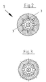
- the depth of the groove 3 is not constant, but in the upper Area in the area of hole 2, within which the Control element 5 can move, the groove depth 3 decreases to the Paragraph 11, with the section of the wall shown in FIG is shown on the left, and which is in bore 2 up to paragraph 11 extends, an approximately parabolic contour of the wall of the jacket part 1 with the groove depth decreasing further inwards.
- flow rates can be regulated with flow controllers
- Use control elements of the type shown in Figure 1 that are similar are built up, considering only the number of available Grooves 3 varies so that, for example, if two are provided Grooves instead of a groove can double the volume flow etc.
- a starting position of the control element 5 see Figure 1, right half of the drawing, in which the maximum Flow cross section through the grooves between control element 5 and Wall of the jacket part 1 is given, serves one end in the Sheath part 1 inserted stop 14.
- the control element 5 has a closed floor so that it covers the entire hole 2 covers the jacket part and the flow of the fluid only laterally the grooves 3 can take place, whereas for example molded sealing lips 6, which are preferably on the front and are attached on the back to the control element 5 on the circumference (see FIG. 6), the control element for the inner wall of the bore 2 of the jacket part 1 seals out, so that there is a side stream of Fluid is prevented. As a result, the volume flow through the Cross section of the groove 3 or the grooves defined.
- valve has a spring-loaded upper lifting part 23, with a valve spindle 22, one at the front end Has closure body 31 which against a valve seat 32 in Housing is movable to allow the passage of the fluid through the valve to close.
- the valve spindle 22 for example is electrically drivable, with a sleeve 34 on the valve spindle 22 sits, which is acted upon by a prestressed spring 35, so that the closing of the closure piece 31 against the force of the Spring 35 takes place.
- the flow controller 1 also preferably has an outside integrally formed sealing lip 38, creating a seal to the housing is created.
- the valve further comprises a housing with an essentially cylindrical middle part 27, of which a first in the lower region Inlet port 26 radially goes through which the fluid into the
- the interior of the housing passes through the flow regulator flows with the control element 5, which is different here than in the previous variant described is a ball, the flow controller in Figure 4 in a position rotated by 180 ° compared to Figure 1 is shown according to the direction of flow of the fluid.
- the valve housing also includes a radial one outgoing outlet connection 28 in the upper area below the Valve upper part 23, so that the outlet port 28 is parallel but with axial offset to the inlet port 26 goes from the cylindrical housing middle part 27. So it is in principle a so-called double corner arrangement with double angular offset in the flow direction, which enables the housing of the Overall, the thermostatic valve is particularly flat because the existing nozzles are all on one level.
- the Input connector 26 and the output connector 28 are in an axial Extension to the housing middle part 27 arranged further Lower nozzle 24 provided, the end in an axial extension of the housing middle part 27 is arranged and this one on opposite end of the short connector 33, which the Valve upper part 23 receives, which for example in the nozzle can be screwed in.
- an annular strainer 21 which consists of a Wire sieve or a similar sieve-like material can exist.
- the strainer 21 is approximately at the level of Arranged inlet connector 26 of the housing, so that there flowing fluid flows through the strainer 21 and in particular coarser particles are kept away from it so these do not get into the area of the control element 5 and its Can impair mobility.
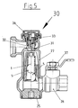
- FIG. 5 shows an alternative variant of the invention, in which the In principle, the valve is constructed in the housing parts just like that The previously described valve according to FIG. 4. Also in the valve according to Figure 5 is the jacket part 1 with the control element 5 in the cylindrical housing middle part 27 used. Different from the previously described thermostatic valve variant is in the variant 5 a manually operable valve upper part 30 in the Stub 33 used so that the valve by operating the Closure body 31, which in turn has a valve seat 32 of the housing is assigned, the valve can open or close.
- the Flow direction and the function of the flow controller with the Control element 5 otherwise corresponds to that previously shown in FIG. 4 described embodiment.
- By unscrewing the Closure piece 25 is the inside of the valve housing for the Service accessible and for example the flow controller 1, 5 can be exchanged.
Landscapes
- Physics & Mathematics (AREA)
- General Physics & Mathematics (AREA)
- Engineering & Computer Science (AREA)
- Automation & Control Theory (AREA)
- Lift Valve (AREA)
- Steering Control In Accordance With Driving Conditions (AREA)
- Flow Control (AREA)
- Temperature-Responsive Valves (AREA)
Abstract
Description
- Fig. 1
- eine Ansicht eines erfindungsgemäßen Durchflussreglers im Längsschnitt;
- Fig. 2
- einen Querschnitt durch den Durchflussregler gemäß Figur 1 entlang der Linie II II von Figur 1;
- Fig. 3
- einen Querschnitt durch den Durchflussregler entlang der Linie III III von Figur 1 gesehen;
- Fig. 4
- einen Längsschnitt durch ein erfindungsgemäßes Thermostatventil, welches sich automatisch öffnen bzw. schließen lässt;
- Fig. 5
- einen Längsschnitt durch ein Ventil gemäß einer Variante der Erfindung, welches manuell geöffnet bzw. geschlossen wird;
- Fig. 6
- eine vergrößerte Einzelansicht eines Regelelements.
- 1.
- Mantelteil
- 2.
- Bohrung
- 3.
- Nut
- 4.
- Druckfeder
- 5.
- Regelelement
- 6.
- Dichtelement
- 8.
- Justierschraube
- 11.
- Absatz
- 12.
- Bohrung
- 13.
- Gewindebohrung
- 14.
- Anschlag
- 21.
- Schmutzfänger
- 22.
- Ventilspindel
- 23.
- Huboberteil
- 24.
- unterer Stutzen
- 25.
- Verschlussstück
- 26.
- Eingangsstutzen
- 27.
- zylindrisches Mittelteil
- 28.
- Ausgangsstutzen
- 30.
- Ventiloberteil
- 31.
- Verschlusskörper
- 32.
- Ventilsitz
- 33.
- Stutzen
- 34.
- Hülse
- 35.
- Feder
- 36.
- Kappe
Claims (22)
- Durchflussregler umfassend ein feststehendes Mantelteil, welches im wesentlichen in axialer Richtung von einem Fluid durchströmt wird und ein innerhalb des Mantelteils gegen eine Federkraft axial verschiebbares Regelelement, wobei der Querschnitt von Durchflussöffnungen durch den Durchflussregler abhängig von der jeweiligen Stellung des Regelelements variiert, dadurch gekennzeichnet, dass das Regelelement (5) eine geschlossene Umfangsfläche aufweist, und dass das Mantelteil (1) in dem Abschnitt, innerhalb dessen das Regelelement (5) verschiebbar ist, einen variierenden Innenquerschnitt aufweist, so dass sich der verfügbare Durchflussquerschnitt für das Fluid zwischen dem äußeren Umfang des Regelelements (5) und dem Innenquerschnitt des Mantelteils (1) bei Einwärtsbewegung des Regelelements reduziert.
- Durchflussregler nach Anspruch 1, dadurch gekennzeichnet, dass das Mantelteil (1) am inneren Umfang wenigstens eine im wesentlichen in axialer Richtung verlaufende Nut oder nutförmige Ausbuchtung (3) aufweist, deren Querschnitt sich in Einwärtsrichtung reduziert.
- Durchflussregler nach Anspruch 1 oder 2, dadurch gekennzeichnet, dass die Nut oder nutförmige Ausbuchtung (3) des Mantelteils (1) im Längsschnitt in axialer Richtung gesehen mindestens abschnittsweise eine parabolische Kontur aufweist.
- Durchflussregler nach einem der Ansprüche 1 bis 3, dadurch gekennzeichnet, dass das Mantelteil (1) eine zylindrische oder leicht kegelförmige Bohrung (2) aufweist, innerhalb der sich das Regelelement (5) bewegt.
- Durchflussregler nach einem der Ansprüche 1 bis 4, dadurch gekennzeichnet, dass das Regelelement (5) in seinem Durchmesser so dimensioniert ist, dass es maßlich passend in der Bohrung (2) des Mantelteils (1) geführt ist.
- Durchflussregler nach einem der Ansprüche 1 bis 5, dadurch gekennzeichnet, dass das Regelelement (5) an seinem Umfang wenigstens ein Dichtelement, vorzugsweise eine Dichtlippe (6) aufweist, die zur Innenwandung der Bohrung (2) hin abdichtet und/oder das Mantelteil (1) am Umfang eine vorzugsweise angeformte Dichtlippe (38) aufweist.
- Durchflussregler nach einem der Ansprüche 1 bis 6, dadurch gekennzeichnet, dass das Regelelement jeweils in beiden endseitigen Bereichen je ein zur Bohrung (2) hin abdichtendes Dichtelement (6), vorzugsweise eine angespritzte Dichtlippe aufweist.
- Durchflussregler nach einem der Ansprüche 1 bis 7, dadurch gekennzeichnet, dass das Regelelement (5) im wesentlichen die Form eines Zylinders oder einer Kugel aufweist.
- Durchflussregler nach einem der Ansprüche 1 bis 8, dadurch gekennzeichnet, dass der sich in axialer Richtung ändernde Innenquerschnitt des Mantelteils (1) so dimensioniert ist, dass bei axialem Hub des Regelelements (5) und sich änderndem Differenzdruck über einen vorgegebenen Druckbereich ein konstanter Volumenstrom des Fluids durch den Durchflussregler erzielt wird.
- Durchflussregler nach einem der Ansprüche 1 bis 9, dadurch gekennzeichnet, dass das Regelelement (5) ein Kunststoffspritzteil ist.
- Durchflussregler nach einem der Ansprüche 1 bis 10, dadurch gekennzeichnet, dass wenigstens eine Nut oder nutförmige Ausbuchtung (3) über die gesamte Länge des Mantelteils (1) geführt ist.
- Durchflussregler nach einem der Ansprüche 1 bis 11, dadurch gekennzeichnet, dass durch einen Absatz (11) am Ende der Bohrung (2) ein Anschlag für das Regelelement (5) in seiner maximalen Hubposition gegeben ist.
- Durchflussregler nach einem der Ansprüche 1 bis 12, dadurch gekennzeichnet, dass der Querschnitt der Nut bzw. nutförmigen Ausbuchtung (3) in der Wandung des Mantelteils (1) in axialer Richtung etwas bis zu dem Absatz (11) hin abnimmt.
- Durchflussregler nach einem der Ansprüche 1 bis 13, dadurch gekennzeichnet, dass der Querschnitt der Nut (3) in der Wandung des Mantelteils (1) in axialer Richtung nichtlinear abnimmt.
- Thermostatventil, dadurch gekennzeichnet, dass in dessen Gehäuse ein Durchflussregler gemäß einem der Ansprüche 1 bis 14 eingesetzt ist.
- Thermostatventil nach Anspruch 15, dadurch gekennzeichnet, dass dieses ein federbelastetes Huboberteil mit Ventilspindel und Verschlussstück aufweist, dem ein Ventilsitz im Gehäuse zugeordnet ist, für ein automatisches Öffnen und Schließen des Ventils.
- Thermostatventil nach Anspruch 15, dadurch gekennzeichnet, dass dieses ein manuell betätigbares Ventiloberteil (30) mit Verschlusskörper (31) aufweist, dem ein Ventilsitz (32) im Gehäuse zugeordnet ist, für ein manuelles Öffnen und Schließen des Ventils.
- Thermostatventil nach einem der Ansprüche 15 bis 17, dadurch gekennzeichnet, dass dieses einen im Innen des Gehäuses angeordneten dem Durchflussregler in Strömungsrichtung vorgeschalteten Schmutzfänger (21), vorzugsweise in Form eines Drahtsiebs aufweist.
- Thermostatventil, vorzugsweise nach einem der Ansprüche 15 bis 18, dadurch gekennzeichnet, dass dieses einen ersten radial abgehenden Eingangsstutzen (26) aufweist, einen im wesentlichen zylindrischen Gehäusemittelteil (27) und einen mit axialem Versatz zu dem Eingangsstutzen (26) ebenfalls radial abgehenden Ausgangsstutzen (28).
- Thermostatventil nach einem der Ansprüche 15 bis 19, dadurch gekennzeichnet, dass das federbelastete Huboberteil (23) bzw. das manuell zu betätigende Ventiloberteil in axialer Verlängerung zu dem Mittelteil (27) des Gehäuses angeordnet ist und die Achse des Ausgangsstutzens (28) rechtwinklig zur Achse der Hubbewegung des Verschlussstücks (31) angeordnet ist.
- Thermostatventil nach einem der Ansprüche 15 bis 20, dadurch gekennzeichnet, dass das Gehäuse einen weiteren Stutzen (24) aufweist, der über ein vorzugsweise einschraubbares Verschlussstück (25) verschließbar und über den das Gehäuseinnere zugänglich ist.
- Thermostatventil nach einem der Ansprüche 15 bis 21, dadurch gekennzeichnet, dass der Stutzen (24) einem das Ventiloberteil (23) aufnehmenden Stutzen (33) in axialer Verlängerung am anderen Ende des Gehäuses gegenüberliegend angeordnet ist.
Applications Claiming Priority (2)
| Application Number | Priority Date | Filing Date | Title |
|---|---|---|---|
| DE10205406 | 2002-02-09 | ||
| DE10205406A DE10205406A1 (de) | 2002-02-09 | 2002-02-09 | Durchflussmengenregler und Ventil mit Durchflussmengenregler |
Publications (2)
| Publication Number | Publication Date |
|---|---|
| EP1341069A1 true EP1341069A1 (de) | 2003-09-03 |
| EP1341069B1 EP1341069B1 (de) | 2006-08-23 |
Family
ID=27618505
Family Applications (1)
| Application Number | Title | Priority Date | Filing Date |
|---|---|---|---|
| EP03002808A Expired - Lifetime EP1341069B1 (de) | 2002-02-09 | 2003-02-07 | Durchflussregler und Ventil mit Durchflussregler |
Country Status (4)
| Country | Link |
|---|---|
| EP (1) | EP1341069B1 (de) |
| AT (1) | ATE337577T1 (de) |
| DE (2) | DE10205406A1 (de) |
| DK (1) | DK1341069T3 (de) |
Citations (4)
| Publication number | Priority date | Publication date | Assignee | Title |
|---|---|---|---|---|
| US3093155A (en) * | 1960-06-20 | 1963-06-11 | Bendix Corp | Variable-restriction valve |
| US4383550A (en) * | 1980-11-26 | 1983-05-17 | Rikuta Sotokazu | Constant flow valve |
| DE20022166U1 (de) * | 2000-12-20 | 2001-06-21 | Huthmann, André, 27632 Midlum | Vorrichtung zum Regeln der Durchflußmenge eines fluiden Mediums |
| US20020100506A1 (en) * | 2000-12-18 | 2002-08-01 | May John Henry | Flow control valve |
Family Cites Families (6)
| Publication number | Priority date | Publication date | Assignee | Title |
|---|---|---|---|---|
| US3015341A (en) * | 1958-01-10 | 1962-01-02 | William Waterman | Flow regulators |
| DE1473034A1 (de) * | 1964-08-11 | 1968-11-07 | Benkisser Werk Kg | Durchflussmengenregler |
| US4306585A (en) * | 1979-10-03 | 1981-12-22 | Manos William S | Constant flow valve |
| DE3310007A1 (de) * | 1983-03-19 | 1984-09-20 | Schlösser GmbH, 5960 Olpe | Thermostatgesteuertes dreiwege-regulierventil, insbesondere fuer einrohr-heizungsanlagen |
| AU7183991A (en) * | 1990-01-08 | 1991-08-05 | Alco Standard Corporation | Fluid flow regulator |
| US5383489A (en) * | 1993-10-26 | 1995-01-24 | Flow Design, Inc. | Flow control valve with enhanced flow control piston |
-
2002
- 2002-02-09 DE DE10205406A patent/DE10205406A1/de not_active Withdrawn
-
2003
- 2003-02-07 AT AT03002808T patent/ATE337577T1/de active
- 2003-02-07 EP EP03002808A patent/EP1341069B1/de not_active Expired - Lifetime
- 2003-02-07 DK DK03002808T patent/DK1341069T3/da active
- 2003-02-07 DE DE50304698T patent/DE50304698D1/de not_active Expired - Lifetime
Patent Citations (4)
| Publication number | Priority date | Publication date | Assignee | Title |
|---|---|---|---|---|
| US3093155A (en) * | 1960-06-20 | 1963-06-11 | Bendix Corp | Variable-restriction valve |
| US4383550A (en) * | 1980-11-26 | 1983-05-17 | Rikuta Sotokazu | Constant flow valve |
| US20020100506A1 (en) * | 2000-12-18 | 2002-08-01 | May John Henry | Flow control valve |
| DE20022166U1 (de) * | 2000-12-20 | 2001-06-21 | Huthmann, André, 27632 Midlum | Vorrichtung zum Regeln der Durchflußmenge eines fluiden Mediums |
Also Published As
| Publication number | Publication date |
|---|---|
| DE50304698D1 (de) | 2006-10-05 |
| DE10205406A1 (de) | 2003-08-21 |
| ATE337577T1 (de) | 2006-09-15 |
| DK1341069T3 (da) | 2007-01-02 |
| EP1341069B1 (de) | 2006-08-23 |
Similar Documents
| Publication | Publication Date | Title |
|---|---|---|
| DE10325846B4 (de) | Druckmindernder Regler | |
| EP3213803B1 (de) | Filter-anordnung | |
| DE3150100C2 (de) | Schwimmergesteuertes Wasserzulaufventil | |
| EP1516237B1 (de) | Durchflussmengenregler | |
| DE69217946T2 (de) | Rückführventil | |
| EP3362713B1 (de) | Poppetventil | |
| EP0061415A1 (de) | Ventil für hydraulische Systeme | |
| DE3817270A1 (de) | Strahlregler | |
| DE2608791A1 (de) | Modulierende stroemungssteuerventilanordnung | |
| DE3338418C2 (de) | ||
| DE202005004196U1 (de) | Durchflussmengenregler | |
| DE202005010233U1 (de) | Hebelbetätigte, automatische Absperranordnung | |
| EP1341069B1 (de) | Durchflussregler und Ventil mit Durchflussregler | |
| DE69516282T2 (de) | Vorrichtung zur regelung des druckes und der strömung in kühl-oder heizanlagen | |
| DE102004049253B4 (de) | Thermostatventil | |
| DE10132001C2 (de) | Thermostatischer Regler zur Regelung der Durchflussmenge eines Fluids | |
| DE19710983C2 (de) | Rückschlagventil | |
| DE102005011947B3 (de) | Durchflussmengenregler | |
| DE10156500C5 (de) | Druckminderungsventil | |
| DE202021100188U1 (de) | Sanitäre Baugruppe zur Erzeugung eines zeitlich variierenden Wasserstrahls | |
| DE102006039730B3 (de) | Einbauventil | |
| DE69212031T2 (de) | Pneumatisches Verbindungssystem mit einem verbesserten Luftregelventil | |
| DE102022132067B4 (de) | Sanitäres Einbauteil und Verwendung eines sanitären Einbauteils | |
| DE20311848U1 (de) | Schlauchbruchventil | |
| EP1536170B1 (de) | Ventil |
Legal Events
| Date | Code | Title | Description |
|---|---|---|---|
| PUAI | Public reference made under article 153(3) epc to a published international application that has entered the european phase |
Free format text: ORIGINAL CODE: 0009012 |
|
| 17P | Request for examination filed |
Effective date: 20030628 |
|
| AK | Designated contracting states |
Kind code of ref document: A1 Designated state(s): AT BE BG CH CY CZ DE DK EE ES FI FR GB GR HU IE IT LI LU MC NL PT SE SI SK TR |
|
| AX | Request for extension of the european patent |
Extension state: AL LT LV MK RO |
|
| AKX | Designation fees paid |
Designated state(s): AT BE BG CH CY CZ DE DK EE ES FI FR GB GR HU IE IT LI LU MC NL PT SE SI SK TR |
|
| RAP1 | Party data changed (applicant data changed or rights of an application transferred) |
Owner name: HONEYWELL TECHNOLOGIES SARL |
|
| GRAP | Despatch of communication of intention to grant a patent |
Free format text: ORIGINAL CODE: EPIDOSNIGR1 |
|
| GRAS | Grant fee paid |
Free format text: ORIGINAL CODE: EPIDOSNIGR3 |
|
| GRAA | (expected) grant |
Free format text: ORIGINAL CODE: 0009210 |
|
| AK | Designated contracting states |
Kind code of ref document: B1 Designated state(s): AT BE BG CH CY CZ DE DK EE ES FI FR GB GR HU IE IT LI LU MC NL PT SE SI SK TR |
|
| PG25 | Lapsed in a contracting state [announced via postgrant information from national office to epo] |
Ref country code: FI Free format text: LAPSE BECAUSE OF FAILURE TO SUBMIT A TRANSLATION OF THE DESCRIPTION OR TO PAY THE FEE WITHIN THE PRESCRIBED TIME-LIMIT Effective date: 20060823 Ref country code: SK Free format text: LAPSE BECAUSE OF FAILURE TO SUBMIT A TRANSLATION OF THE DESCRIPTION OR TO PAY THE FEE WITHIN THE PRESCRIBED TIME-LIMIT Effective date: 20060823 Ref country code: IE Free format text: LAPSE BECAUSE OF FAILURE TO SUBMIT A TRANSLATION OF THE DESCRIPTION OR TO PAY THE FEE WITHIN THE PRESCRIBED TIME-LIMIT Effective date: 20060823 Ref country code: SI Free format text: LAPSE BECAUSE OF FAILURE TO SUBMIT A TRANSLATION OF THE DESCRIPTION OR TO PAY THE FEE WITHIN THE PRESCRIBED TIME-LIMIT Effective date: 20060823 Ref country code: IT Free format text: LAPSE BECAUSE OF FAILURE TO SUBMIT A TRANSLATION OF THE DESCRIPTION OR TO PAY THE FEE WITHIN THE PRESCRIBED TIME-LIMIT;WARNING: LAPSES OF ITALIAN PATENTS WITH EFFECTIVE DATE BEFORE 2007 MAY HAVE OCCURRED AT ANY TIME BEFORE 2007. THE CORRECT EFFECTIVE DATE MAY BE DIFFERENT FROM THE ONE RECORDED. Effective date: 20060823 |
|
| REG | Reference to a national code |
Ref country code: GB Ref legal event code: FG4D Free format text: NOT ENGLISH |
|
| REG | Reference to a national code |
Ref country code: CH Ref legal event code: EP |
|
| REG | Reference to a national code |
Ref country code: IE Ref legal event code: FG4D Free format text: LANGUAGE OF EP DOCUMENT: GERMAN |
|
| REF | Corresponds to: |
Ref document number: 50304698 Country of ref document: DE Date of ref document: 20061005 Kind code of ref document: P |
|
| PG25 | Lapsed in a contracting state [announced via postgrant information from national office to epo] |
Ref country code: BG Free format text: LAPSE BECAUSE OF FAILURE TO SUBMIT A TRANSLATION OF THE DESCRIPTION OR TO PAY THE FEE WITHIN THE PRESCRIBED TIME-LIMIT Effective date: 20061123 |
|
| REG | Reference to a national code |
Ref country code: SE Ref legal event code: TRGR |
|
| PG25 | Lapsed in a contracting state [announced via postgrant information from national office to epo] |
Ref country code: ES Free format text: LAPSE BECAUSE OF FAILURE TO SUBMIT A TRANSLATION OF THE DESCRIPTION OR TO PAY THE FEE WITHIN THE PRESCRIBED TIME-LIMIT Effective date: 20061204 |
|
| GBT | Gb: translation of ep patent filed (gb section 77(6)(a)/1977) |
Effective date: 20061115 |
|
| REG | Reference to a national code |
Ref country code: DK Ref legal event code: T3 |
|
| PG25 | Lapsed in a contracting state [announced via postgrant information from national office to epo] |
Ref country code: PT Free format text: LAPSE BECAUSE OF FAILURE TO SUBMIT A TRANSLATION OF THE DESCRIPTION OR TO PAY THE FEE WITHIN THE PRESCRIBED TIME-LIMIT Effective date: 20070124 |
|
| PG25 | Lapsed in a contracting state [announced via postgrant information from national office to epo] |
Ref country code: MC Free format text: LAPSE BECAUSE OF NON-PAYMENT OF DUE FEES Effective date: 20070228 |
|
| REG | Reference to a national code |
Ref country code: IE Ref legal event code: FD4D |
|
| ET | Fr: translation filed | ||
| PLBE | No opposition filed within time limit |
Free format text: ORIGINAL CODE: 0009261 |
|
| STAA | Information on the status of an ep patent application or granted ep patent |
Free format text: STATUS: NO OPPOSITION FILED WITHIN TIME LIMIT |
|
| 26N | No opposition filed |
Effective date: 20070524 |
|
| BERE | Be: lapsed |
Owner name: HONEYWELL TECHNOLOGIES SARL Effective date: 20070228 |
|
| PG25 | Lapsed in a contracting state [announced via postgrant information from national office to epo] |
Ref country code: BE Free format text: LAPSE BECAUSE OF NON-PAYMENT OF DUE FEES Effective date: 20070228 |
|
| PG25 | Lapsed in a contracting state [announced via postgrant information from national office to epo] |
Ref country code: GR Free format text: LAPSE BECAUSE OF FAILURE TO SUBMIT A TRANSLATION OF THE DESCRIPTION OR TO PAY THE FEE WITHIN THE PRESCRIBED TIME-LIMIT Effective date: 20061124 |
|
| PG25 | Lapsed in a contracting state [announced via postgrant information from national office to epo] |
Ref country code: EE Free format text: LAPSE BECAUSE OF FAILURE TO SUBMIT A TRANSLATION OF THE DESCRIPTION OR TO PAY THE FEE WITHIN THE PRESCRIBED TIME-LIMIT Effective date: 20060823 |
|
| PG25 | Lapsed in a contracting state [announced via postgrant information from national office to epo] |
Ref country code: LU Free format text: LAPSE BECAUSE OF NON-PAYMENT OF DUE FEES Effective date: 20070207 Ref country code: CY Free format text: LAPSE BECAUSE OF FAILURE TO SUBMIT A TRANSLATION OF THE DESCRIPTION OR TO PAY THE FEE WITHIN THE PRESCRIBED TIME-LIMIT Effective date: 20060823 |
|
| PG25 | Lapsed in a contracting state [announced via postgrant information from national office to epo] |
Ref country code: HU Free format text: LAPSE BECAUSE OF FAILURE TO SUBMIT A TRANSLATION OF THE DESCRIPTION OR TO PAY THE FEE WITHIN THE PRESCRIBED TIME-LIMIT Effective date: 20070224 Ref country code: TR Free format text: LAPSE BECAUSE OF FAILURE TO SUBMIT A TRANSLATION OF THE DESCRIPTION OR TO PAY THE FEE WITHIN THE PRESCRIBED TIME-LIMIT Effective date: 20060823 |
|
| REG | Reference to a national code |
Ref country code: FR Ref legal event code: PLFP Year of fee payment: 14 |
|
| REG | Reference to a national code |
Ref country code: FR Ref legal event code: PLFP Year of fee payment: 15 |
|
| REG | Reference to a national code |
Ref country code: FR Ref legal event code: PLFP Year of fee payment: 16 |
|
| PGFP | Annual fee paid to national office [announced via postgrant information from national office to epo] |
Ref country code: NL Payment date: 20190225 Year of fee payment: 17 |
|
| PGFP | Annual fee paid to national office [announced via postgrant information from national office to epo] |
Ref country code: CH Payment date: 20190225 Year of fee payment: 17 Ref country code: IT Payment date: 20190221 Year of fee payment: 17 Ref country code: CZ Payment date: 20190206 Year of fee payment: 17 Ref country code: GB Payment date: 20190227 Year of fee payment: 17 |
|
| PGFP | Annual fee paid to national office [announced via postgrant information from national office to epo] |
Ref country code: FR Payment date: 20190226 Year of fee payment: 17 Ref country code: AT Payment date: 20190227 Year of fee payment: 17 Ref country code: SE Payment date: 20190222 Year of fee payment: 17 Ref country code: DK Payment date: 20190225 Year of fee payment: 17 |
|
| REG | Reference to a national code |
Ref country code: DK Ref legal event code: EBP Effective date: 20200229 |
|
| REG | Reference to a national code |
Ref country code: SE Ref legal event code: EUG |
|
| REG | Reference to a national code |
Ref country code: CH Ref legal event code: PL |
|
| REG | Reference to a national code |
Ref country code: NL Ref legal event code: MM Effective date: 20200301 |
|
| REG | Reference to a national code |
Ref country code: AT Ref legal event code: MM01 Ref document number: 337577 Country of ref document: AT Kind code of ref document: T Effective date: 20200207 |
|
| GBPC | Gb: european patent ceased through non-payment of renewal fee |
Effective date: 20200207 |
|
| PG25 | Lapsed in a contracting state [announced via postgrant information from national office to epo] |
Ref country code: SE Free format text: LAPSE BECAUSE OF NON-PAYMENT OF DUE FEES Effective date: 20200208 Ref country code: CZ Free format text: LAPSE BECAUSE OF NON-PAYMENT OF DUE FEES Effective date: 20200207 |
|
| PG25 | Lapsed in a contracting state [announced via postgrant information from national office to epo] |
Ref country code: CH Free format text: LAPSE BECAUSE OF NON-PAYMENT OF DUE FEES Effective date: 20200229 Ref country code: LI Free format text: LAPSE BECAUSE OF NON-PAYMENT OF DUE FEES Effective date: 20200229 Ref country code: AT Free format text: LAPSE BECAUSE OF NON-PAYMENT OF DUE FEES Effective date: 20200207 |
|
| PG25 | Lapsed in a contracting state [announced via postgrant information from national office to epo] |
Ref country code: NL Free format text: LAPSE BECAUSE OF NON-PAYMENT OF DUE FEES Effective date: 20200301 |
|
| PG25 | Lapsed in a contracting state [announced via postgrant information from national office to epo] |
Ref country code: GB Free format text: LAPSE BECAUSE OF NON-PAYMENT OF DUE FEES Effective date: 20200207 Ref country code: DK Free format text: LAPSE BECAUSE OF NON-PAYMENT OF DUE FEES Effective date: 20200229 Ref country code: FR Free format text: LAPSE BECAUSE OF NON-PAYMENT OF DUE FEES Effective date: 20200229 |
|
| PG25 | Lapsed in a contracting state [announced via postgrant information from national office to epo] |
Ref country code: IT Free format text: LAPSE BECAUSE OF NON-PAYMENT OF DUE FEES Effective date: 20200207 |
|
| PGFP | Annual fee paid to national office [announced via postgrant information from national office to epo] |
Ref country code: DE Payment date: 20220329 Year of fee payment: 20 |
|
| REG | Reference to a national code |
Ref country code: DE Ref legal event code: R071 Ref document number: 50304698 Country of ref document: DE |