EP1338488A1 - Maítre-cylindre pour systeme de freinage electro-hydraulique - Google Patents
Maítre-cylindre pour systeme de freinage electro-hydraulique Download PDFInfo
- Publication number
- EP1338488A1 EP1338488A1 EP03003859A EP03003859A EP1338488A1 EP 1338488 A1 EP1338488 A1 EP 1338488A1 EP 03003859 A EP03003859 A EP 03003859A EP 03003859 A EP03003859 A EP 03003859A EP 1338488 A1 EP1338488 A1 EP 1338488A1
- Authority
- EP
- European Patent Office
- Prior art keywords
- master cylinder
- spring
- piston
- cartridge
- pedal
- Prior art date
- Legal status (The legal status is an assumption and is not a legal conclusion. Google has not performed a legal analysis and makes no representation as to the accuracy of the status listed.)
- Granted
Links
Images


Classifications
-
- B—PERFORMING OPERATIONS; TRANSPORTING
- B60—VEHICLES IN GENERAL
- B60T—VEHICLE BRAKE CONTROL SYSTEMS OR PARTS THEREOF; BRAKE CONTROL SYSTEMS OR PARTS THEREOF, IN GENERAL; ARRANGEMENT OF BRAKING ELEMENTS ON VEHICLES IN GENERAL; PORTABLE DEVICES FOR PREVENTING UNWANTED MOVEMENT OF VEHICLES; VEHICLE MODIFICATIONS TO FACILITATE COOLING OF BRAKES
- B60T8/00—Arrangements for adjusting wheel-braking force to meet varying vehicular or ground-surface conditions, e.g. limiting or varying distribution of braking force
- B60T8/32—Arrangements for adjusting wheel-braking force to meet varying vehicular or ground-surface conditions, e.g. limiting or varying distribution of braking force responsive to a speed condition, e.g. acceleration or deceleration
- B60T8/34—Arrangements for adjusting wheel-braking force to meet varying vehicular or ground-surface conditions, e.g. limiting or varying distribution of braking force responsive to a speed condition, e.g. acceleration or deceleration having a fluid pressure regulator responsive to a speed condition
- B60T8/40—Arrangements for adjusting wheel-braking force to meet varying vehicular or ground-surface conditions, e.g. limiting or varying distribution of braking force responsive to a speed condition, e.g. acceleration or deceleration having a fluid pressure regulator responsive to a speed condition comprising an additional fluid circuit including fluid pressurising means for modifying the pressure of the braking fluid, e.g. including wheel driven pumps for detecting a speed condition, or pumps which are controlled by means independent of the braking system
- B60T8/4072—Systems in which a driver input signal is used as a control signal for the additional fluid circuit which is normally used for braking
- B60T8/4081—Systems with stroke simulating devices for driver input
- B60T8/409—Systems with stroke simulating devices for driver input characterised by details of the stroke simulating device
-
- B—PERFORMING OPERATIONS; TRANSPORTING
- B60—VEHICLES IN GENERAL
- B60T—VEHICLE BRAKE CONTROL SYSTEMS OR PARTS THEREOF; BRAKE CONTROL SYSTEMS OR PARTS THEREOF, IN GENERAL; ARRANGEMENT OF BRAKING ELEMENTS ON VEHICLES IN GENERAL; PORTABLE DEVICES FOR PREVENTING UNWANTED MOVEMENT OF VEHICLES; VEHICLE MODIFICATIONS TO FACILITATE COOLING OF BRAKES
- B60T11/00—Transmitting braking action from initiating means to ultimate brake actuator without power assistance or drive or where such assistance or drive is irrelevant
- B60T11/10—Transmitting braking action from initiating means to ultimate brake actuator without power assistance or drive or where such assistance or drive is irrelevant transmitting by fluid means, e.g. hydraulic
- B60T11/16—Master control, e.g. master cylinders
- B60T11/20—Tandem, side-by-side, or other multiple master cylinder units
-
- B—PERFORMING OPERATIONS; TRANSPORTING
- B60—VEHICLES IN GENERAL
- B60T—VEHICLE BRAKE CONTROL SYSTEMS OR PARTS THEREOF; BRAKE CONTROL SYSTEMS OR PARTS THEREOF, IN GENERAL; ARRANGEMENT OF BRAKING ELEMENTS ON VEHICLES IN GENERAL; PORTABLE DEVICES FOR PREVENTING UNWANTED MOVEMENT OF VEHICLES; VEHICLE MODIFICATIONS TO FACILITATE COOLING OF BRAKES
- B60T7/00—Brake-action initiating means
- B60T7/02—Brake-action initiating means for personal initiation
- B60T7/04—Brake-action initiating means for personal initiation foot actuated
- B60T7/042—Brake-action initiating means for personal initiation foot actuated by electrical means, e.g. using travel or force sensors
-
- B—PERFORMING OPERATIONS; TRANSPORTING
- B60—VEHICLES IN GENERAL
- B60T—VEHICLE BRAKE CONTROL SYSTEMS OR PARTS THEREOF; BRAKE CONTROL SYSTEMS OR PARTS THEREOF, IN GENERAL; ARRANGEMENT OF BRAKING ELEMENTS ON VEHICLES IN GENERAL; PORTABLE DEVICES FOR PREVENTING UNWANTED MOVEMENT OF VEHICLES; VEHICLE MODIFICATIONS TO FACILITATE COOLING OF BRAKES
- B60T8/00—Arrangements for adjusting wheel-braking force to meet varying vehicular or ground-surface conditions, e.g. limiting or varying distribution of braking force
- B60T8/32—Arrangements for adjusting wheel-braking force to meet varying vehicular or ground-surface conditions, e.g. limiting or varying distribution of braking force responsive to a speed condition, e.g. acceleration or deceleration
- B60T8/34—Arrangements for adjusting wheel-braking force to meet varying vehicular or ground-surface conditions, e.g. limiting or varying distribution of braking force responsive to a speed condition, e.g. acceleration or deceleration having a fluid pressure regulator responsive to a speed condition
- B60T8/40—Arrangements for adjusting wheel-braking force to meet varying vehicular or ground-surface conditions, e.g. limiting or varying distribution of braking force responsive to a speed condition, e.g. acceleration or deceleration having a fluid pressure regulator responsive to a speed condition comprising an additional fluid circuit including fluid pressurising means for modifying the pressure of the braking fluid, e.g. including wheel driven pumps for detecting a speed condition, or pumps which are controlled by means independent of the braking system
- B60T8/4072—Systems in which a driver input signal is used as a control signal for the additional fluid circuit which is normally used for braking
- B60T8/4081—Systems with stroke simulating devices for driver input
Definitions
- the present invention relates mainly to a master cylinder for a system of electro-hydraulic braking with improved means for simulating the pedal feel and an electro-hydraulic braking system including such master cylinder.
- Electro-hydraulic braking systems include a simulating master cylinder, in normal operation, the mechanical reaction of a conventional braking circuit felt at the brake pedal by a driver, and means for detecting the action of the driver on the brake pedal sending the information to a computer which generates order a hydraulic pump to send pressurized brake fluid to the brakes.
- the master cylinder supplies brake fluid under pressure to the brakes as in a circuit classic braking.
- the master cylinder for an electro-hydraulic braking system of known type have a body of substantially cylindrical shape in which a bore divided into at least one supply chamber and one working chamber by a piston mounted to slide tightly in the bore and actuated by a rod actuation connected to a brake pedal
- the piston allows a rest communication between the two chambers and a tight separation of the two chambers during a braking action.
- the feed chamber is connected so sealed to a brake fluid reservoir and the working chamber is in operation normal connected to a pedal sensation simulation cartridge or pedal feeling and in degraded operation with at least one brake arranged at the level of a wheel.
- the pedal feel cartridge comprises an envelope delimiting a substantially cylindrical chamber in which slides a piston subjected in normal operation during a braking phase by a first face to the pressurized brake fluid supplied by the working chamber and by a second face. at a first end of an elastic means, the second end of the elastic means pressing against the bottom of the chamber opposite the piston.
- the elastic means makes it possible to simulate the mechanical reaction of a conventional braking circuit, which corresponds to a relationship linking the force to the pedal as a function of the stroke of the pedal.
- the characteristic curve of this relationship includes at least a first part corresponding to the absorption of the braking circuit at the start of the braking phase, then a second part corresponding to an increasingly significant reaction with the increase in the braking level.
- the elastic means of known type used in pedal feel cartridges are therefore very complex and expensive, they comprise for example several helical springs, of different loads, with constant pitch and with variable pitch, elastomer elements to simulate absorption of the circuit.
- the assembly is long and consequently increases the cost price due to the large number of parts necessary to correctly simulate a conventional pedal reaction.
- electro-hydraulic braking systems allow excellent control of the braking and of the vehicle, however the means of simulating the reaction of the circuit braking are relatively complex and require precise adjustment, their application to a wide range of vehicles is therefore not possible.
- a master cylinder comprising a cartridge for simulating the pedal sensation comprising an elastic means reproducing the reaction of a circuit conventional braking, the elastic means comprising a helical spring and a means spacer placed between at least two consecutive turns of the coil spring carrying two axially opposite bearing surfaces for the two turns and modifying the stiffness of the elastic means when the turns come to bear on the means spacer.
- the elastic means comprises a spring provided with several turns, coupled to a spacer inserted between several turns of the spring, thus forming pairs of spring turns separated by a spacer turn; when increasing the load undergone by the spring, the coils of the spring come gradually and continuously in contact with the spacer parts arranged between each pair of turns, causing a gradual and continuous increase in the stiffness of the means elastic and thus a reaction to the brake pedal close to the reaction of a classic braking.
- the stiffness of the elastic means determines the reaction of the cartridge of simulation of the pedal sensation
- the stiffness of the elastic means being inversely proportional to the number of active turns of the coil spring, are called turns activates the turns moving axially relative to the other turns when a load is applied to the spring.
- zones of turns of the spring gradually come into contact with the means spacer until said zones of turns become fixed relative to the zone deires the next or the previous in the direction of application of the load, the zone of next or previous turn being a “deactivated” turn area and forming support for deactivation of the active coil area.
- the spacer is of variable section along the axis of the spring, which therefore allows to have a variation of the modification of the stiffness of the means elastic offering a reaction very close to a reaction of a braking circuit classic.
- reaction felt at the brake pedal can be modified, by changing the position relative to the spacer means relative to the spring, one can then provide a device allowing for example to modify the variation of stiffness of the means elastic, advantageously controlled by a computer of the braking system.
- the main object of the present invention is a master cylinder for electro-hydraulic braking comprising a body of longitudinal axis pierced with a bore, a piston mounted for sliding sliding in the bore and axially dividing the bore in a supply chamber tightly connected to a liquid tank brake and in a working chamber, said piston being controlled by a rod actuation connected to a brake pedal, and a cartridge for simulating the reaction of a braking circuit to the pedal, said working chamber being in communication during normal operation with the inside of the simulation cartridge pedal feeling and in degraded operation with at least one brake disposed at the level of a wheel, said cartridge comprising a piston capable of being subjected by a first face of the pressurized brake fluid supplied by the working chamber, and subjected by a second face to an elastic means with variable stiffness characterized in that that the elastic means comprises at least one helical spring and a means spacer placed between at least two turns of said spring and allowing support said turns on said spacer means beyond a predetermined value of brake fluid
- the present invention also relates to a master cylinder characterized in that the spacer means is formed by a helix forming turns
- the present invention also relates to a master cylinder characterized in that the propeller of the cartridge has a dimension section along the longitudinal axis continuously increasing or decreasing per portion of propeller.
- the present invention also relates to a master cylinder characterized in that the spacer means is made of plastic.
- the present invention also relates to a master cylinder characterized in that the helical spring is regular pitch.
- the present invention also relates to a master cylinder characterized in that the spacer means comprises a second longitudinal end mounted fixed by compared to the cartridge piston.
- the present invention also relates to a master cylinder characterized in that the cartridge includes means for adjusting the pedal feel simulated by modification of the axial position of the spacer means relative to the spring.
- the present invention also relates to a master cylinder characterized in that said adjustment means comprises a stepping electric motor allowing a longitudinal and rotational movement of the spacer means.
- the present invention also relates to an electro-hydraulic braking system
- an electro-hydraulic braking system comprising means for detecting the braking action of the driver, a computer receiving the information from the detection means and generating orders control to cause the actuation of at least one brake arranged at the level of a wheel, a pressure generator receiving the command from the computer to send pressurized fluid in the brakes, a master cylinder allowing the simulation of the pedal feel during normal operation and serving as a brake fluid source under pressure in degraded operation, and solenoid valves to interrupt the communication between said master cylinder and the brakes in normal operation, characterized in that said master cylinder is a master cylinder according to the invention.
- the present invention also relates to a braking system characterized in that that the pressure generator is an electric pump.
- a master cylinder of known type comprising a body 2 of longitudinal axis X pierced with a bore 4 of axis X blind, divided into a primary hydraulic circuit 6 and a secondary hydraulic circuit 8
- the primary and secondary hydraulic circuits being of similar structure we will only describe the primary circuit 6.
- the primary circuit 6 comprises a hydraulic piston 10 mounted for leaktight sliding in the bore 4 by means of lip seal 12 mounted in an annular groove 14 formed on the periphery of the piston 10.
- the piston 10 receives in its rear part a longitudinal end front 16 of an actuating rod 18 shaped as a ball joint, the actuating rod being connected by a rear longitudinal end 20 to a brake pedal (not shown) arranged in the passenger compartment of the vehicle.
- the piston 10 divides the bore 4 into a supply chamber 22 disposed behind the piston 10 and into a working chamber 24 in front of the piston 10.
- the supply chamber is connected by sealed means 24 to a reservoir of brake fluid 26 and the working chamber is connected in normal operation to a cartridge for simulating the pedal feel 28 and in degraded operation to brakes arranged at the wheels.
- the piston 10 has in its central part a longitudinal passage 30 provided with a valve 32 bringing the supply chamber and the chamber to communication and isolating the two chambers 22,24 during a braking phase.
- a return means 25 of the piston 10 is arranged in the primary working chamber 24.
- the secondary circuit is never connected in a way hydraulic to the cartridge 28. Indeed in normal operation, the working chamber secondary 34 is isolated from the braking circuit and in degraded operation, the chamber secondary work is connected to the brakes by a channel 36 open in the rest state and in the summer degraded and connecting the secondary working chamber 34 to the brakes.
- the secondary piston 31 has an O-ring 35 on its outer periphery cooperating in degraded operation with a shoulder 33 formed on the periphery of bore 4 and interrupting the communication between the working chamber 24 and inside the cartridge 28.
- the cartridge for simulating the pedal feel 28 of axis Y substantially perpendicular to the axis X of the body of the master cylinder comprises an envelope 38 in a substantially U shape.
- the envelope comprises an open end 37 fixed in leaktight manner to the body of the master cylinder and a bottom 39, and defines an interior chamber 40 in which is mounted with sliding sliding a piston 42 subjected on a first face 44 to the pressure prevailing in the primary working chamber 24 and on a second face 46 opposite to the first face 44 to the reaction of an elastic means 48.
- the brake fluid is conveyed from the working chamber 24 to the cartridge by a channel 50 formed in the body of the master cylinder substantially perpendicular to the axis X.
- the body of the master cylinder 2 comprises a first 43 and a second 41 coaxial sleeves of axis Y, the first sleeve 43 borders the channel 50 and receives in leaktight sliding part of the piston 42, the second, sleeve 41 surrounds the first sleeve 43 and comprise means 45 for fixing the cartridge to the body of the master cylinder, for example screw nut 45.
- the piston 42 is composite and comprises a first tubular part 422 in sealed sliding in the first sleeve 43 by means of lip seals arranged in a groove 424 formed in the external peripheral of the first part 422.
- the first tubular part 422 has a first longitudinal end 426 closed by a bottom 428 opposite the channel 50 and a second longitudinal end 430 opposite the first end 426 receiving a second part 425 of the piston 42 T-shaped facing downwards, the foot of the T 432 being slidably mounted in the first tubular part 422.
- a helical spring 434 is mounted in compression between the head 436 of the T 425 and a shoulder formed in the first tubular part 422.
- the piston 42 also includes a third part 438 in the shape of a U oriented from the bottom. above in the figure, and surrounding the first sleeve 43, the bottom 440 of the U 438 receiving the head 436 of the second part 425.
- the third part has at its end upper open a flange 442 extending radi
- An elastic pad 444 for example made of elastomer, is disposed between the bottom 428 of the first part 422 and the foot of the T 432.
- the elastic means 48 for simulating the pedal sensation comprises the first spring helical coil 434 with constant pitch, a helical spring 60 with variable pitch mounted in compression between the bottom 39 of the envelope and the collar 442 and a stud 62 in elastomer pinched between the bottom 39 of the cartridge and a longitudinal end lower 64 of the spring 60, said stud ensuring the simulation of the sensation of the reaction to the pedal in maximum braking at the end of the stroke for a braking circuit classic.
- the springs 434.60 during a braking action, work in their area of elastic deformation.
- the piston 10 When applied to the brake pedal, the piston 10 moves in the direction indicated by the arrow A against the spring 25 causing the valve 32 to close and the chambers 22 and 24 to be isolated, the volume of the working chamber 24 reducing, the pressure increases in the working chamber acting on the first face 44 of the piston 42.
- the piston 42 moves according to arrow B to l against spring 434, then spring 60.
- the spring 434 makes it possible to simulate the absorption of a conventional braking circuit, then because of the variability of the pitch of the spring 60, the relationship between the displacement of the piston 42 and the pressure applied to the first face 44 of the piston 42 is not linear and approaches the reaction of a conventional braking circuit (FIG. 2)
- the piston comes to crush the stud 62 by the small base 54 which simulates the saturation in a conventional braking circuit.
- the secondary circuit piston does not move.
- channel 36 of the secondary circuit is open and the displacement of the primary piston 10 causes the displacement of the secondary piston 31 which closes the communication between the working chamber 24 and the cartridge 28 by application of the O-ring 35 against the shoulder 33 .
- the master cylinder operates then like a classic master cylinder.
- the master cylinder as described above is satisfactory however it is of a complex realization and it does not allow to modify the reaction simulated by the cartridge.
- electro-hydraulic braking systems with a master cylinder single circuit, that is to say comprising only one pressure piston and by therefore only one working chamber connected in normal operation to the pedal feel cartridge and supplying two or four brakes in the event of failure arranged at the wheels.
- FIG. 3 one can see a cartridge for simulating the pedal sensation 32 according to the present invention.
- the master cylinder is identical to that described above, by therefore we will only describe cartridge 32.
- the cartridge 32 comprises a casing 38 of axis Y having substantially the shape of a U, the upper part of the U forming a first end longitudinal 37 open of the cartridge which is tightly connected to the body 2 of the master cylinder.
- a second longitudinal end opposite the first end 37 forming the bottom 39 of the cartridge is advantageously pierced with an orifice 66 bordered by a substantially annular collar 68 and allowing the passage of a means of setting.
- the casing 38 defines an interior chamber 40 in which is mounted sealed sliding of a piston 42, the sealing being produced for example by means a lip seal 70 fixedly mounted in an annular groove 72 formed on the periphery of the piston 42 facing the interior lateral surface of the chamber 40, the shape of the piston 42 is of course not limiting, and the use of a piston as shown in Figure 1 is not beyond the scope of the present invention.
- the piston 42 sealingly divides the chamber 40 into an upper chamber hydraulic 74 delimited in part by a first face 44 of the piston 42 and in a “dry” lower chamber 76 delimited by a second face 46 of the piston 42, the room 76 is qualified as “dry” since, unlike room 74, it does not receives no brake fluid.
- the envelope 38 also comprises an elastic means 48 mounted in the lower chamber 76, the elastic means comprising at least one helical spring 78 of axis Y mounted in compression between the second face 46 of the piston 42 and a bottom 79 of the envelope , advantageously formed by an annular surface 68 delimiting an orifice 60.
- the spring 78 according to the embodiment shown is a helical spring with regular pitch, which means that the spring 78 comprises first turns Sn spaced apart by an interval of constant dimension, in the example shown it includes the turns S1, S2 , S3, S4, S5, S6 spaced respectively by intervals I1, I2, I3, I4, I5 of constant length d.
- Spring 78 during a braking action, works in its deformation range elastic.
- the elastic means 48 also includes a spacer means 80 (FIG. 3 ′) with an axis Y of advantageously helical shape comprising second turns Zn, in the example shown it includes Z1, Z2, Z3, Z4, Z5.
- Spacer means 80 is suitable to cooperate with the spring 78 so that the second turns Z1, Z2, Z3, Z4, Z5 are arranged respectively in the intervals I1, I2, I3, I4, I5.
- the turns Zn of the spacer means 80 are of sufficient transverse dimension to allow the support of the coils Sn of the helical spring 78.
- the spacer means 80 is of taper substantially equal to that of spring 78.
- the spacer means 80 has a free upper end (not shown) and a lower end 83 fixed either to a plug closing the orifice 60 after setting place of the spacer means, that is to say adjustment means 82 of pedal feel simulated.
- the spring 78 may include any number of turns Sn and the spacer means may have a different number of turns than that of the number of intervals In
- the propeller forming the spacer means 80 is provided with turns of axial dimension e along the axis Y continuously decreasing in the direction of the arrow C.
- the section of turns referenced Z1, Z2, Z3 , Z4, Z5 visible in Figure 3 are respectively of axial dimension e1, e2, e3, e4, e5, e2 being less than e1, e3 being less than e2, e4 being less than e3 and e5 being less than e4.
- the spacer means can be placed in the casing 38 and between the turns of the spring 78 in the opposite direction so that the propeller forming the spacer means 80 is of axial dimension e along the Y axis continuously increasing in the direction of arrow C.
- a spacer means 80 formed by a propeller of axial dimension along the Y axis varying in a non-monotonous manner does not leave the frame of the present invention.
- the propeller advantageously has a rectangular cross section, however a propeller having for example a circular or elliptical cross section does not depart from the scope of this invention.
- n is a positive integer greater than or equal to one.
- the spacer means 80 is advantageously made of deforming plastic weakly in an elastic manner in the working range of the elastic means 48, however the use for example of metallic materials or any other material allowing an elastic approximation of the Zn turns of the spacer means and forming however a rigid spacer between the Sn turns of the spring 78 does not go beyond the frame of the present invention.
- the embodiment as shown also includes the means 82 for adjusting the simulated pedal sensation, making it possible to modify in particular the first part of the effort-stroke characteristic, and this by modifying the indexing of the turns Z1, Z2, Z3, Z4, Z5 in the intervals I1, I2, I3, I4, I5, by modifying the axial position of the spacer means 80 relative to the spring 78, in particular the situation of the turns Z1, Z2, Z3, Z4, Z5 in the intervals I1, I2, I3, I4, I5, which modifies the thickness of the spacer part arranged between the turns of the spring 78.
- the adjustment means 82 make it possible to move the turn Zn from the interval In in the direction of the interval In + 1 or In-1 depending on the modification of the pedal feeling sought, for example the turn Z5 is likely to be moved from interval I5 to interval I4 and so on.
- the adjustment means 82 comprise for example an electric stepping motor allowing to screw in the direction of the arrow V or to unscrew in the direction of the arrow D the spacer means 80 in the spring 78, the turns Z1, Z2, Z3, Z4, Z5 forming the thread and the intervals I1, I2, I3, I4, I5 forming the thread.
- Characteristic C1 includes a first part P1 corresponding to the start of the displacement of the piston 42 which has the effect of compressing the spring 78, the intervals I1, I2, I3, I4, I5 see their length decrease simultaneously.
- the dimension d of intervals I1, I2, I3, I4, I5 is greater than the dimension e1, the zones of turns S1 and S2 are not yet in contact with the coil zone Z1.
- the variation of the slope is done continuously, which corresponds to a feeling pedal very close to the sensation felt with a conventional braking circuit.
- the piston 42 continues to compress spring 78 causing new contacts between the turns of the spring 78 and the turns of the spacer means and successive increases the slope of the characteristic.
- the characteristic C1 will have a slope of constant stiffness until the turns of the spring are not separated by a turn of the spacer means and therefore still likely to come together for a force of increasing application comes into contact simultaneously, the spring can no longer compress elastically which no longer corresponds to normal operation of the master cylinder.
- the elastic means 48 corresponds to a variable pitch spring. editable.
- An elastic means comprising a variable pitch spring and a spacer means provided of coil of constant axial dimension or not does not depart from the scope of this invention.
- axis Y of the cartridge can be oriented in any other way that perpendicular to the X axis of the body of the master cylinder
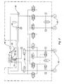
- an electro-hydraulic braking system comprising a master cylinder MC according to the present invention actuated by the actuating rod 18 connected to a brake pedal 86, means for detection 88 of the longitudinal displacement of the actuating rod 18 for example race sensors, a computer 90 receiving the information of the means of detection 88 and generating control orders to cause the actuation of brakes 92, a pressure generator 94 for example an electric pump receiving the order from the computer 90 to send pressurized fluid to the brakes 92 and solenoid valves 96 to interrupt the communication between the master cylinder and the brakes in normal operation, these being open at rest and in operation degraded.
- the detection means 88 sends the information to the computer 90 which generates the order to the pump 94 to send fluid under pressure in the brakes 92.
- a simulated reaction corresponding to a circuit conventional braking is transmitted to the driver by the brake pedal giving him the possibility of adjusting its braking level.
- a master cylinder comprising a single hydraulic circuit formed a supply chamber and a pressure chamber, the pressure chamber being connected to a pedal sensation simulation cartridge comprising a elastic means according to the present invention does not depart from the scope of the present invention
- a master cylinder comprising means for simulating the effective pedal feel and simple implementation, and advantageously allowing a simple and quick adaptation of these master cylinders to different vehicle models the technique and / or an adaptation to the wishes of the driver of the vehicle.
- the present invention is particularly applicable to the automotive industry.
- the present invention applies in particular to the vehicle braking industry automotive and in particular to the braking industry for private cars.
Landscapes
- Engineering & Computer Science (AREA)
- Physics & Mathematics (AREA)
- Fluid Mechanics (AREA)
- Transportation (AREA)
- Mechanical Engineering (AREA)
- Braking Systems And Boosters (AREA)
- Transmission Of Braking Force In Braking Systems (AREA)
- Regulating Braking Force (AREA)
- Springs (AREA)
- Braking Elements And Transmission Devices (AREA)
- Braking Arrangements (AREA)
Abstract
Description
Les moyens élastiques de type connu utilisés dans les cartouches de sensation pédale sont par conséquent très complexes et coûteux, ils comportent par exemple plusieurs ressorts hélicoïdaux, de charges différentes, à pas constant et à pas variable, des éléments en élastomère pour simuler l'absorption du circuit. De plus le montage est long et augmente par conséquent le prix de revient du fait du grand nombre de pièces nécessaires pour simuler correctement une réaction pédale classique.
Le circuit primaire 6 comporte un piston hydraulique 10 monté à coulissement étanche dans l'alésage 4 au moyen de joint à lèvre 12 monté dans un gorge annulaire 14 pratiquée sur la périphérie du piston 10. Le piston 10 reçoit dans sa partie arrière une extrémité longitudinale avant 16 d'une tige d'actionnement 18 conformée en rotule, la tige d'actionnement étant reliée par un extrémité longitudinale arrière 20 à une pédale de frein (non représentée) disposée dans l'habitacle du véhicule. La piston 10 divise l'alésage 4 en une chambre d'alimentation 22 disposée en arrière du piston 10 et en une chambre de travail 24 en avant du piston 10. La chambre d'alimentation est raccordée par des moyens étanches 24 à un réservoir de liquide de frein 26 et la chambre de travail est raccordée en fonctionnement normal à une cartouche de simulation de la sensation pédale 28 et en fonctionnement dégradé à des freins disposés au niveau des roues.
L'acheminement du liquide de frein de la chambre de travail 24 à la cartouche s'effectue par un canal 50 pratiqué dans le corps du maítre-cylindre sensiblement perpendiculairement à l'axe X.
Le corps du maítre-cylindre 2 comporte un premier 43 et un second 41 manchons coaxiaux d'axe Y, le premier manchon 43 borde le canal 50 et reçoit à coulissement étanche une partie du piston 42, le second, manchon 41 entour le premier manchon 43 et comportent des moyens de fixation 45 de la cartouche au corps du maítre-cylindre par exemple vis écrou 45.
Tout d'abord, le ressort 434 permet de simuler l'absorption d'un circuit de freinage classique, puis du fait de la variabilité du pas du ressort 60, la relation entre le déplacement du piston 42 et la pression appliquée sur la première face 44 du piston 42 n'est pas linéaire et se rapproche de la réaction d'un circuit de freinage classique (figure 2)
En fin de course, correspondant un effort de freinage maximum, le piston vient écrasé le téton 62 par la petite base 54 ce qui simule la saturation dans un circuit de freinage classique.
Le piston du circuit secondaire ne se déplace pas.
Le ressort 78 selon le mode de réalisation représenté est un ressort hélicoïdal à pas régulier, ce qui signifie que le ressort 78 comporte des premières spires Sn espacées d'un intervalle de dimension constante, dans l'exemple représenté il comporte les spires S1, S2, S3, S4, S5, S6 espacées respectivement par des intervalles I1, I2, I3, I4, I5 de longueur d constante.
sont respectivement de dimension axiale e1, e2, e3, e4, e5, e2 étant inférieure à e1, e3 étant inférieure à e2, e4 étant inférieure à e3 et e5 étant inférieure à e4.
Ainsi les moyens d'ajustement 82 permettent de déplacer la spire Zn de l'intervalle In en direction de l'intervalle In+1 ou In-1 suivant la modification de la sensation pédale recherchée, par exemple la spire Z5 est susceptible d'être déplacée de l'intervalle I5 vers l'intervalle I4 et ainsi de suite.
Claims (10)
- Maítre-cylindre pour systèmes de freinage électro-hydraulique comportant un corps (2) d'axe longitudinal (X) percé d'un alésage (4), un piston (10) monté à coulissement étanche dans l'alésage et divisant axialement l'alésage en une chambre d'alimentation (22) raccordée de manière étanche à un réservoir de liquide de frein (R) et en une chambre de travail (24), ledit piston étant commandé par une tige d'actionnement reliée à une pédale de frein, et une cartouche de simulation de la réaction d'un circuit de freinage à la pédale, ladite chambre de travail (24) étant en communication en fonctionnement normal avec l'intérieur de la cartouche (28) de simulation de la sensation pédale et en fonctionnement dégradé avec au moins un frein disposé au niveau d'une roue, ladite cartouche (28) comportant un piston (42) susceptible d'être soumis par une première face (44) au liquide de frein sous pression fourni par la chambre de travail (22), et soumis par une seconde face (46) à un moyen élastique (48) à raideur variable caractérisé en ce que le moyen élastique (48) comporte au moins un ressort hélicoïdal (78) et un moyen d'entretoise (80) disposé entre au moins deux spires (Sn) dudit ressort (78) et permettant l'appui desdites spires sur ledit moyen d'entretoise (80) au delà d'une valeur prédéterminée de pression du liquide de frein dans la chambre de travail (24).
- Maítre-cylindre selon la revendication 1 caractérisé en ce que le moyen d'entretoise (80) est formé par une hélice formant des spires (Zn).
- Maítre-cylindre selon la revendication 2 caractérisé en ce que l'hélice a une section de dimension selon l'axe longitudinale continûment croissante ou décroissante par portion d'hélice.
- Maítre-cylindre selon la revendication 1, 2 ou 3 caractérisé en ce que le moyen d'entretoise (80) est réalisé en matière plastique.
- Maítre-cylindre selon la revendication 1 à 4 caractérisé en ce que le ressort hélicoïdal (78) est à pas régulier.
- Maítre-cylindre selon l'une quelconque des revendications précédentes caractérisé en ce que le moyen d'entretoise comporte une seconde extrémité longitudinale (83) monté fixe par rapport au piston (42) de la cartouche (28).
- Maítre-cylindre selon l'une quelconque des revendications précédentes caractérisé en ce que la cartouche (28) comporte des moyens d'ajustement de la sensation pédale simulée par modification de la position axiale du moyen d'entretoise (80) relativement au ressort (78).
- Maítre-cylindre selon la revendication précédente caractérisé en ce que lesdits moyens d'ajustement comporte un moteur électrique pas à pas permettant un déplacement longitudinal et en rotation du moyen d'entretoise (80).
- Système de freinage électro-hydraulique comportant des moyens de détection 88 de l'action de freinage du conducteur, un calculateur 90 recevant les informations des moyens de détection 88 et générant des ordres de commande pour provoquer l'actionnement d'au moins un frein 92 disposé au niveau d'une roue, un générateur de pression 94 recevant l'ordre du calculateur 90 d'envoyer du liquide sous pression dans les freins 92, un maítre-cylindre permettant la simulation de la sensation pédale en fonctionnement normal et servant de source de liquide de frein sous pression en fonctionnement dégradé, et des électrovannes 96 pour interrompre la communication entre ledit maítre-cylindre et les freins en fonctionnement normal, caractérisé en ce que ledit maítre-cylindre est un maítre-cylindre selon l'une quelconque des revendications précédentes.
- Système de freinage selon la revendication précédente caractérisé en ce que le générateur de pression (94) est une pompe électrique.
Applications Claiming Priority (2)
| Application Number | Priority Date | Filing Date | Title |
|---|---|---|---|
| FR0202440A FR2836441B1 (fr) | 2002-02-25 | 2002-02-25 | Maitre-cylindre pour systeme de freinage electro-hydraulique comportant des moyens ameliores de simulation de la sensation pedale et systeme de freinage electro-hydraulique comportant un tel maitre-cylindre |
| FR0202440 | 2002-02-25 |
Publications (2)
| Publication Number | Publication Date |
|---|---|
| EP1338488A1 true EP1338488A1 (fr) | 2003-08-27 |
| EP1338488B1 EP1338488B1 (fr) | 2010-07-14 |
Family
ID=27636443
Family Applications (1)
| Application Number | Title | Priority Date | Filing Date |
|---|---|---|---|
| EP03003859A Expired - Lifetime EP1338488B1 (fr) | 2002-02-25 | 2003-02-20 | Maître-cylindre pour systeme de freinage electro-hydraulique |
Country Status (7)
| Country | Link |
|---|---|
| US (1) | US6746088B2 (fr) |
| EP (1) | EP1338488B1 (fr) |
| JP (1) | JP4510388B2 (fr) |
| AT (1) | ATE473896T1 (fr) |
| DE (1) | DE60333320D1 (fr) |
| ES (1) | ES2348416T3 (fr) |
| FR (1) | FR2836441B1 (fr) |
Cited By (4)
| Publication number | Priority date | Publication date | Assignee | Title |
|---|---|---|---|---|
| US6746088B2 (en) * | 2002-02-25 | 2004-06-08 | Robert Bosch Gmbh | Master cylinder |
| EP2711256A4 (fr) * | 2011-05-16 | 2016-05-11 | Bosch Gmbh Robert | Simulateur de course, maître cylindre le comportant et système de freinage utilisant le maître cylindre |
| CN112298139A (zh) * | 2020-11-09 | 2021-02-02 | 苏州海之博电子科技有限公司 | 一种踏板模拟机构的运行方法 |
| CN116691612A (zh) * | 2022-02-24 | 2023-09-05 | 沃尔沃汽车公司 | 制动踏板模拟器,制动踏板感觉选择模块及车辆制动系统 |
Families Citing this family (20)
| Publication number | Priority date | Publication date | Assignee | Title |
|---|---|---|---|---|
| FR2834264B1 (fr) * | 2001-12-31 | 2004-02-27 | Bosch Gmbh Robert | Circuit electro-hydraulique de freinage d'un vehicule |
| FR2836439B1 (fr) * | 2002-02-25 | 2004-05-28 | Bosch Gmbh Robert | Maitre-cylindre pour systeme de freinage electro-hydraulique comportant des moyens ameliores de simulation de la sensation pedale et systeme de freinage electro-hydraulique comportant un tel maitre-cylindre |
| JP4206887B2 (ja) * | 2003-09-30 | 2009-01-14 | 株式会社日立製作所 | マスタシリンダ装置 |
| JP2005104332A (ja) * | 2003-09-30 | 2005-04-21 | Hitachi Ltd | マスタシリンダ装置 |
| JP4281525B2 (ja) * | 2003-11-20 | 2009-06-17 | 日産自動車株式会社 | 車両のブレーキ装置 |
| JP4313243B2 (ja) * | 2004-04-26 | 2009-08-12 | 豊田鉄工株式会社 | 車両用電気式操作装置 |
| KR100987145B1 (ko) * | 2004-12-08 | 2010-10-11 | 주식회사 만도 | 전자식 유압브레이크용 마스터실린더 |
| JP4835415B2 (ja) * | 2006-12-08 | 2011-12-14 | トヨタ自動車株式会社 | 運動変換伝達装置 |
| JP2008143333A (ja) * | 2006-12-08 | 2008-06-26 | Toyota Motor Corp | 操作シミュレータ |
| JP5120247B2 (ja) * | 2008-12-26 | 2013-01-16 | トヨタ自動車株式会社 | ブレーキ制御装置 |
| US8936322B2 (en) | 2010-04-20 | 2015-01-20 | Robert Bosch Gmbh | Brake system with selector valve for selecting between two modes of operation |
| US8523294B2 (en) | 2010-04-20 | 2013-09-03 | Robert Bosch Gmbh | Vehicular brake system operable in dual modes |
| US8561401B2 (en) * | 2010-07-29 | 2013-10-22 | Robert Bosch Gmbh | Pedal feel simulator actuator and cutoff assembly |
| WO2012067196A1 (fr) * | 2010-11-17 | 2012-05-24 | 本田技研工業株式会社 | Système de freinage de véhicule |
| JP2012240601A (ja) | 2011-05-23 | 2012-12-10 | Bosch Corp | ストロークシミュレータ、このストロークシミュレータを有するマスタシリンダ、およびこのマスタシリンダを用いたブレーキシステム |
| JP2013023006A (ja) | 2011-07-19 | 2013-02-04 | Bosch Corp | ストロークシミュレータ、このストロークシミュレータを有するマスタシリンダ、およびこのマスタシリンダを用いたブレーキシステム |
| DE102015204681A1 (de) * | 2014-04-03 | 2015-10-08 | Schaeffler Technologies AG & Co. KG | Pedalkraftsimulationsvorrichtung |
| FR3027370B1 (fr) * | 2014-10-15 | 2016-12-23 | Commissariat Energie Atomique | Assemblage de mise en compression de siege de vanne a boule |
| DE102016223736A1 (de) * | 2016-11-30 | 2018-05-30 | Robert Bosch Gmbh | Elektrohydraulischer Fremdkraft-Druckerzeuger |
| CN110027527B (zh) * | 2018-01-12 | 2021-10-22 | 比亚迪股份有限公司 | 踏板模拟器和具有其的线控制动系统、车辆 |
Citations (5)
| Publication number | Priority date | Publication date | Assignee | Title |
|---|---|---|---|---|
| DE10026309A1 (de) * | 1999-05-28 | 2000-12-21 | Aisin Seiki | Bremsdrucksteuervorrichtung für Kraftfahrzeuge |
| US6192685B1 (en) * | 1997-12-22 | 2001-02-27 | Robert Bosch Gmbh | Master cylinder for motor vehicle electro-hydraulic braking installation |
| DE19952778A1 (de) * | 1999-11-03 | 2001-05-23 | Daimler Chrysler Ag | Pedalanordnung für ein Brake-by-Wire-System |
| WO2001068427A1 (fr) * | 2000-03-15 | 2001-09-20 | Continental Teves Ag & Co. Ohg | Systeme de freinage electro-hydraulique |
| WO2001072566A2 (fr) * | 2000-03-27 | 2001-10-04 | Continental Teves Ag & Co. Ohg | Unite d'actionnement pour systeme de freinage electrohydraulique |
Family Cites Families (10)
| Publication number | Priority date | Publication date | Assignee | Title |
|---|---|---|---|---|
| US3141660A (en) * | 1961-03-08 | 1964-07-21 | Woodhead Monroe Ltd | Coil springs |
| JPS63176836A (ja) * | 1987-01-16 | 1988-07-21 | Miura Seisakusho:Kk | プラスチツク製コイルばね |
| JPH0571481U (ja) * | 1992-03-06 | 1993-09-28 | エヌ・オー・ケー・メグラスティック株式会社 | 緩衝装置 |
| JPH0581546U (ja) * | 1992-04-07 | 1993-11-05 | 株式会社ショーワ | 自動二輪車用フロントフォーク |
| JP3768574B2 (ja) * | 1995-11-27 | 2006-04-19 | 三菱電機株式会社 | エレベータのブレーキ装置 |
| JPH09280282A (ja) * | 1996-04-11 | 1997-10-28 | Mitsubishi Denki Bill Techno Service Kk | ブレーキ装置 |
| JP3600025B2 (ja) * | 1998-08-04 | 2004-12-08 | 株式会社リコー | 形状測定装置 |
| JP2000135976A (ja) * | 1998-10-30 | 2000-05-16 | Tokico Ltd | ブレーキストロークシミュレータ装置 |
| FR2836439B1 (fr) * | 2002-02-25 | 2004-05-28 | Bosch Gmbh Robert | Maitre-cylindre pour systeme de freinage electro-hydraulique comportant des moyens ameliores de simulation de la sensation pedale et systeme de freinage electro-hydraulique comportant un tel maitre-cylindre |
| FR2836441B1 (fr) * | 2002-02-25 | 2004-05-28 | Bosch Gmbh Robert | Maitre-cylindre pour systeme de freinage electro-hydraulique comportant des moyens ameliores de simulation de la sensation pedale et systeme de freinage electro-hydraulique comportant un tel maitre-cylindre |
-
2002
- 2002-02-25 FR FR0202440A patent/FR2836441B1/fr not_active Expired - Fee Related
-
2003
- 2003-02-20 EP EP03003859A patent/EP1338488B1/fr not_active Expired - Lifetime
- 2003-02-20 AT AT03003859T patent/ATE473896T1/de not_active IP Right Cessation
- 2003-02-20 DE DE60333320T patent/DE60333320D1/de not_active Expired - Lifetime
- 2003-02-20 ES ES03003859T patent/ES2348416T3/es not_active Expired - Lifetime
- 2003-02-24 US US10/373,468 patent/US6746088B2/en not_active Expired - Fee Related
- 2003-02-25 JP JP2003047812A patent/JP4510388B2/ja not_active Expired - Fee Related
Patent Citations (5)
| Publication number | Priority date | Publication date | Assignee | Title |
|---|---|---|---|---|
| US6192685B1 (en) * | 1997-12-22 | 2001-02-27 | Robert Bosch Gmbh | Master cylinder for motor vehicle electro-hydraulic braking installation |
| DE10026309A1 (de) * | 1999-05-28 | 2000-12-21 | Aisin Seiki | Bremsdrucksteuervorrichtung für Kraftfahrzeuge |
| DE19952778A1 (de) * | 1999-11-03 | 2001-05-23 | Daimler Chrysler Ag | Pedalanordnung für ein Brake-by-Wire-System |
| WO2001068427A1 (fr) * | 2000-03-15 | 2001-09-20 | Continental Teves Ag & Co. Ohg | Systeme de freinage electro-hydraulique |
| WO2001072566A2 (fr) * | 2000-03-27 | 2001-10-04 | Continental Teves Ag & Co. Ohg | Unite d'actionnement pour systeme de freinage electrohydraulique |
Cited By (4)
| Publication number | Priority date | Publication date | Assignee | Title |
|---|---|---|---|---|
| US6746088B2 (en) * | 2002-02-25 | 2004-06-08 | Robert Bosch Gmbh | Master cylinder |
| EP2711256A4 (fr) * | 2011-05-16 | 2016-05-11 | Bosch Gmbh Robert | Simulateur de course, maître cylindre le comportant et système de freinage utilisant le maître cylindre |
| CN112298139A (zh) * | 2020-11-09 | 2021-02-02 | 苏州海之博电子科技有限公司 | 一种踏板模拟机构的运行方法 |
| CN116691612A (zh) * | 2022-02-24 | 2023-09-05 | 沃尔沃汽车公司 | 制动踏板模拟器,制动踏板感觉选择模块及车辆制动系统 |
Also Published As
| Publication number | Publication date |
|---|---|
| JP4510388B2 (ja) | 2010-07-21 |
| ATE473896T1 (de) | 2010-07-15 |
| US6746088B2 (en) | 2004-06-08 |
| FR2836441A1 (fr) | 2003-08-29 |
| ES2348416T3 (es) | 2010-12-03 |
| FR2836441B1 (fr) | 2004-05-28 |
| JP2004001694A (ja) | 2004-01-08 |
| EP1338488B1 (fr) | 2010-07-14 |
| US20030160504A1 (en) | 2003-08-28 |
| DE60333320D1 (de) | 2010-08-26 |
Similar Documents
| Publication | Publication Date | Title |
|---|---|---|
| EP1338488B1 (fr) | Maître-cylindre pour systeme de freinage electro-hydraulique | |
| EP1338489B1 (fr) | Maître-cylindre pour systeme de freinage electro-hydraulique | |
| EP2303656B1 (fr) | Servomoteur hydraulique d'assistance au freinage comportant un moteur | |
| FR2860474A1 (fr) | Servomoteur electrique d'assistance au freinage et vehicule comportant un tel servomoteur | |
| EP0912382B1 (fr) | Dispositif de freinage assiste a rapport d'assistance variable | |
| EP0057640A2 (fr) | Système de freinage pour véhicule automobile formé d'un tracteur et d'une remorque | |
| FR2526881A1 (fr) | Amplificateur hydraulique de puissance, notamment pour l'actionnement de maitres-cylindres de freinage pour l'automobile | |
| EP0939713B1 (fr) | Dispositif de freinage assiste a rapport d'assistance variable et hysteresis reduite | |
| EP1600347B1 (fr) | Simulateur d'actionnement de frein, maître-cylindre pour frein de vehicule automobile, et procede de commande de ce simulateur | |
| EP2666687B1 (fr) | Système de freins a servofrein électrique et procédé de gestion d'un tel système de freins | |
| EP0475794B1 (fr) | Procédé de réglage de la valeur du saut d'un servomoteur pneumatique d'assistance au freinage et servomoteuer pour la mise en oeuvre de ce procédé | |
| EP1024986A1 (fr) | Maitre-cylindre a clapets a course morte reduite | |
| EP0939715B1 (fr) | Systeme de feinage assiste a reaction hydraulique amelioree | |
| EP0802868A1 (fr) | Dispositif de freinage assiste a course reduite | |
| EP0784553A1 (fr) | Electrovalve de regulation de pression hydraulique et application aux circuits de freinage | |
| EP1291257B1 (fr) | Simulateur de sensation de freinage et installation de freinage hydraulique avec un tel simulateur | |
| EP1518770B1 (fr) | Maitre-cylindre à sécurité accrue | |
| EP0991556B1 (fr) | Servomoteur pneumatique d'assistance au freinage a clapet perfectionne | |
| EP1522478B1 (fr) | Servomoteur d'assistance pneumatique au freinage à course morte réduite et système de freinage comportant un tel servomoteur | |
| WO2002094626A1 (fr) | Servomoteur d'assistance pneumatique au freinage a hauteur de saut variable | |
| WO2004048176A1 (fr) | Maitre cylindre pour systeme de freinage electro-hydraulique | |
| WO2002102634A2 (fr) | Servomoteur d'assistance pneumatique au freinage a hauteur de saut variable. | |
| EP1693264A1 (fr) | Servomoteur d'assistance pneumatique au freinage a course morte reduite et maître-cylindre de freinage pour un tel servomoteur | |
| FR2861036A1 (fr) | Systeme de freinage incluant un disque de reaction monte de maniere amelioree | |
| FR3050159A1 (fr) | Dispositif de commande d'un frein d'une remorque |
Legal Events
| Date | Code | Title | Description |
|---|---|---|---|
| PUAI | Public reference made under article 153(3) epc to a published international application that has entered the european phase |
Free format text: ORIGINAL CODE: 0009012 |
|
| AK | Designated contracting states |
Designated state(s): AT BE BG CH CY CZ DE DK EE ES FI FR GB GR HU IE IT LI LU MC NL PT SE SI SK TR |
|
| AX | Request for extension of the european patent |
Extension state: AL LT LV MK RO |
|
| 17P | Request for examination filed |
Effective date: 20040227 |
|
| AKX | Designation fees paid |
Designated state(s): AT BE BG CH CY CZ DE DK EE ES FI FR GB GR HU IE IT LI LU MC NL PT SE SI SK TR |
|
| GRAP | Despatch of communication of intention to grant a patent |
Free format text: ORIGINAL CODE: EPIDOSNIGR1 |
|
| GRAS | Grant fee paid |
Free format text: ORIGINAL CODE: EPIDOSNIGR3 |
|
| GRAA | (expected) grant |
Free format text: ORIGINAL CODE: 0009210 |
|
| AK | Designated contracting states |
Kind code of ref document: B1 Designated state(s): AT BE BG CH CY CZ DE DK EE ES FI FR GB GR HU IE IT LI LU MC NL PT SE SI SK TR |
|
| REG | Reference to a national code |
Ref country code: GB Ref legal event code: FG4D Free format text: NOT ENGLISH |
|
| REG | Reference to a national code |
Ref country code: CH Ref legal event code: EP |
|
| REG | Reference to a national code |
Ref country code: IE Ref legal event code: FG4D |
|
| REF | Corresponds to: |
Ref document number: 60333320 Country of ref document: DE Date of ref document: 20100826 Kind code of ref document: P |
|
| REG | Reference to a national code |
Ref country code: NL Ref legal event code: VDEP Effective date: 20100714 |
|
| REG | Reference to a national code |
Ref country code: ES Ref legal event code: FG2A Effective date: 20101123 |
|
| PG25 | Lapsed in a contracting state [announced via postgrant information from national office to epo] |
Ref country code: AT Free format text: LAPSE BECAUSE OF FAILURE TO SUBMIT A TRANSLATION OF THE DESCRIPTION OR TO PAY THE FEE WITHIN THE PRESCRIBED TIME-LIMIT Effective date: 20100714 Ref country code: FI Free format text: LAPSE BECAUSE OF FAILURE TO SUBMIT A TRANSLATION OF THE DESCRIPTION OR TO PAY THE FEE WITHIN THE PRESCRIBED TIME-LIMIT Effective date: 20100714 Ref country code: NL Free format text: LAPSE BECAUSE OF FAILURE TO SUBMIT A TRANSLATION OF THE DESCRIPTION OR TO PAY THE FEE WITHIN THE PRESCRIBED TIME-LIMIT Effective date: 20100714 |
|
| REG | Reference to a national code |
Ref country code: IE Ref legal event code: FD4D |
|
| PG25 | Lapsed in a contracting state [announced via postgrant information from national office to epo] |
Ref country code: SI Free format text: LAPSE BECAUSE OF FAILURE TO SUBMIT A TRANSLATION OF THE DESCRIPTION OR TO PAY THE FEE WITHIN THE PRESCRIBED TIME-LIMIT Effective date: 20100714 Ref country code: PT Free format text: LAPSE BECAUSE OF FAILURE TO SUBMIT A TRANSLATION OF THE DESCRIPTION OR TO PAY THE FEE WITHIN THE PRESCRIBED TIME-LIMIT Effective date: 20101115 Ref country code: BG Free format text: LAPSE BECAUSE OF FAILURE TO SUBMIT A TRANSLATION OF THE DESCRIPTION OR TO PAY THE FEE WITHIN THE PRESCRIBED TIME-LIMIT Effective date: 20101014 Ref country code: CY Free format text: LAPSE BECAUSE OF FAILURE TO SUBMIT A TRANSLATION OF THE DESCRIPTION OR TO PAY THE FEE WITHIN THE PRESCRIBED TIME-LIMIT Effective date: 20100714 |
|
| PG25 | Lapsed in a contracting state [announced via postgrant information from national office to epo] |
Ref country code: SE Free format text: LAPSE BECAUSE OF FAILURE TO SUBMIT A TRANSLATION OF THE DESCRIPTION OR TO PAY THE FEE WITHIN THE PRESCRIBED TIME-LIMIT Effective date: 20100714 Ref country code: GR Free format text: LAPSE BECAUSE OF FAILURE TO SUBMIT A TRANSLATION OF THE DESCRIPTION OR TO PAY THE FEE WITHIN THE PRESCRIBED TIME-LIMIT Effective date: 20101015 |
|
| PG25 | Lapsed in a contracting state [announced via postgrant information from national office to epo] |
Ref country code: IE Free format text: LAPSE BECAUSE OF FAILURE TO SUBMIT A TRANSLATION OF THE DESCRIPTION OR TO PAY THE FEE WITHIN THE PRESCRIBED TIME-LIMIT Effective date: 20100714 Ref country code: DK Free format text: LAPSE BECAUSE OF FAILURE TO SUBMIT A TRANSLATION OF THE DESCRIPTION OR TO PAY THE FEE WITHIN THE PRESCRIBED TIME-LIMIT Effective date: 20100714 |
|
| PLBE | No opposition filed within time limit |
Free format text: ORIGINAL CODE: 0009261 |
|
| STAA | Information on the status of an ep patent application or granted ep patent |
Free format text: STATUS: NO OPPOSITION FILED WITHIN TIME LIMIT |
|
| PG25 | Lapsed in a contracting state [announced via postgrant information from national office to epo] |
Ref country code: CZ Free format text: LAPSE BECAUSE OF FAILURE TO SUBMIT A TRANSLATION OF THE DESCRIPTION OR TO PAY THE FEE WITHIN THE PRESCRIBED TIME-LIMIT Effective date: 20100714 Ref country code: SK Free format text: LAPSE BECAUSE OF FAILURE TO SUBMIT A TRANSLATION OF THE DESCRIPTION OR TO PAY THE FEE WITHIN THE PRESCRIBED TIME-LIMIT Effective date: 20100714 Ref country code: EE Free format text: LAPSE BECAUSE OF FAILURE TO SUBMIT A TRANSLATION OF THE DESCRIPTION OR TO PAY THE FEE WITHIN THE PRESCRIBED TIME-LIMIT Effective date: 20100714 |
|
| 26N | No opposition filed |
Effective date: 20110415 |
|
| REG | Reference to a national code |
Ref country code: DE Ref legal event code: R097 Ref document number: 60333320 Country of ref document: DE Effective date: 20110415 |
|
| BERE | Be: lapsed |
Owner name: ROBERT BOSCH G.M.B.H. Effective date: 20110228 |
|
| PG25 | Lapsed in a contracting state [announced via postgrant information from national office to epo] |
Ref country code: MC Free format text: LAPSE BECAUSE OF NON-PAYMENT OF DUE FEES Effective date: 20110228 |
|
| REG | Reference to a national code |
Ref country code: CH Ref legal event code: PL |
|
| PG25 | Lapsed in a contracting state [announced via postgrant information from national office to epo] |
Ref country code: LI Free format text: LAPSE BECAUSE OF NON-PAYMENT OF DUE FEES Effective date: 20110228 Ref country code: CH Free format text: LAPSE BECAUSE OF NON-PAYMENT OF DUE FEES Effective date: 20110228 |
|
| PG25 | Lapsed in a contracting state [announced via postgrant information from national office to epo] |
Ref country code: BE Free format text: LAPSE BECAUSE OF NON-PAYMENT OF DUE FEES Effective date: 20110228 |
|
| PG25 | Lapsed in a contracting state [announced via postgrant information from national office to epo] |
Ref country code: LU Free format text: LAPSE BECAUSE OF NON-PAYMENT OF DUE FEES Effective date: 20110220 |
|
| PG25 | Lapsed in a contracting state [announced via postgrant information from national office to epo] |
Ref country code: TR Free format text: LAPSE BECAUSE OF FAILURE TO SUBMIT A TRANSLATION OF THE DESCRIPTION OR TO PAY THE FEE WITHIN THE PRESCRIBED TIME-LIMIT Effective date: 20100714 |
|
| PG25 | Lapsed in a contracting state [announced via postgrant information from national office to epo] |
Ref country code: HU Free format text: LAPSE BECAUSE OF FAILURE TO SUBMIT A TRANSLATION OF THE DESCRIPTION OR TO PAY THE FEE WITHIN THE PRESCRIBED TIME-LIMIT Effective date: 20100714 |
|
| PGFP | Annual fee paid to national office [announced via postgrant information from national office to epo] |
Ref country code: FR Payment date: 20140218 Year of fee payment: 12 |
|
| REG | Reference to a national code |
Ref country code: FR Ref legal event code: ST Effective date: 20151030 |
|
| PG25 | Lapsed in a contracting state [announced via postgrant information from national office to epo] |
Ref country code: FR Free format text: LAPSE BECAUSE OF NON-PAYMENT OF DUE FEES Effective date: 20150302 |
|
| PGFP | Annual fee paid to national office [announced via postgrant information from national office to epo] |
Ref country code: IT Payment date: 20160222 Year of fee payment: 14 Ref country code: ES Payment date: 20160223 Year of fee payment: 14 |
|
| PGFP | Annual fee paid to national office [announced via postgrant information from national office to epo] |
Ref country code: GB Payment date: 20160222 Year of fee payment: 14 |
|
| PGFP | Annual fee paid to national office [announced via postgrant information from national office to epo] |
Ref country code: DE Payment date: 20170427 Year of fee payment: 15 |
|
| GBPC | Gb: european patent ceased through non-payment of renewal fee |
Effective date: 20170220 |
|
| PG25 | Lapsed in a contracting state [announced via postgrant information from national office to epo] |
Ref country code: IT Free format text: LAPSE BECAUSE OF NON-PAYMENT OF DUE FEES Effective date: 20170220 Ref country code: GB Free format text: LAPSE BECAUSE OF NON-PAYMENT OF DUE FEES Effective date: 20170220 |
|
| REG | Reference to a national code |
Ref country code: ES Ref legal event code: FD2A Effective date: 20180706 |
|
| REG | Reference to a national code |
Ref country code: DE Ref legal event code: R119 Ref document number: 60333320 Country of ref document: DE |
|
| PG25 | Lapsed in a contracting state [announced via postgrant information from national office to epo] |
Ref country code: ES Free format text: LAPSE BECAUSE OF NON-PAYMENT OF DUE FEES Effective date: 20170221 |
|
| PG25 | Lapsed in a contracting state [announced via postgrant information from national office to epo] |
Ref country code: DE Free format text: LAPSE BECAUSE OF NON-PAYMENT OF DUE FEES Effective date: 20180901 |