EP1338488A1 - Master-cylinder for electro-hydraulic brake system - Google Patents
Master-cylinder for electro-hydraulic brake system Download PDFInfo
- Publication number
- EP1338488A1 EP1338488A1 EP03003859A EP03003859A EP1338488A1 EP 1338488 A1 EP1338488 A1 EP 1338488A1 EP 03003859 A EP03003859 A EP 03003859A EP 03003859 A EP03003859 A EP 03003859A EP 1338488 A1 EP1338488 A1 EP 1338488A1
- Authority
- EP
- European Patent Office
- Prior art keywords
- master cylinder
- spring
- piston
- cartridge
- pedal
- Prior art date
- Legal status (The legal status is an assumption and is not a legal conclusion. Google has not performed a legal analysis and makes no representation as to the accuracy of the status listed.)
- Granted
Links
Images


Classifications
-
- B—PERFORMING OPERATIONS; TRANSPORTING
- B60—VEHICLES IN GENERAL
- B60T—VEHICLE BRAKE CONTROL SYSTEMS OR PARTS THEREOF; BRAKE CONTROL SYSTEMS OR PARTS THEREOF, IN GENERAL; ARRANGEMENT OF BRAKING ELEMENTS ON VEHICLES IN GENERAL; PORTABLE DEVICES FOR PREVENTING UNWANTED MOVEMENT OF VEHICLES; VEHICLE MODIFICATIONS TO FACILITATE COOLING OF BRAKES
- B60T8/00—Arrangements for adjusting wheel-braking force to meet varying vehicular or ground-surface conditions, e.g. limiting or varying distribution of braking force
- B60T8/32—Arrangements for adjusting wheel-braking force to meet varying vehicular or ground-surface conditions, e.g. limiting or varying distribution of braking force responsive to a speed condition, e.g. acceleration or deceleration
- B60T8/34—Arrangements for adjusting wheel-braking force to meet varying vehicular or ground-surface conditions, e.g. limiting or varying distribution of braking force responsive to a speed condition, e.g. acceleration or deceleration having a fluid pressure regulator responsive to a speed condition
- B60T8/40—Arrangements for adjusting wheel-braking force to meet varying vehicular or ground-surface conditions, e.g. limiting or varying distribution of braking force responsive to a speed condition, e.g. acceleration or deceleration having a fluid pressure regulator responsive to a speed condition comprising an additional fluid circuit including fluid pressurising means for modifying the pressure of the braking fluid, e.g. including wheel driven pumps for detecting a speed condition, or pumps which are controlled by means independent of the braking system
- B60T8/4072—Systems in which a driver input signal is used as a control signal for the additional fluid circuit which is normally used for braking
- B60T8/4081—Systems with stroke simulating devices for driver input
- B60T8/409—Systems with stroke simulating devices for driver input characterised by details of the stroke simulating device
-
- B—PERFORMING OPERATIONS; TRANSPORTING
- B60—VEHICLES IN GENERAL
- B60T—VEHICLE BRAKE CONTROL SYSTEMS OR PARTS THEREOF; BRAKE CONTROL SYSTEMS OR PARTS THEREOF, IN GENERAL; ARRANGEMENT OF BRAKING ELEMENTS ON VEHICLES IN GENERAL; PORTABLE DEVICES FOR PREVENTING UNWANTED MOVEMENT OF VEHICLES; VEHICLE MODIFICATIONS TO FACILITATE COOLING OF BRAKES
- B60T11/00—Transmitting braking action from initiating means to ultimate brake actuator without power assistance or drive or where such assistance or drive is irrelevant
- B60T11/10—Transmitting braking action from initiating means to ultimate brake actuator without power assistance or drive or where such assistance or drive is irrelevant transmitting by fluid means, e.g. hydraulic
- B60T11/16—Master control, e.g. master cylinders
- B60T11/20—Tandem, side-by-side, or other multiple master cylinder units
-
- B—PERFORMING OPERATIONS; TRANSPORTING
- B60—VEHICLES IN GENERAL
- B60T—VEHICLE BRAKE CONTROL SYSTEMS OR PARTS THEREOF; BRAKE CONTROL SYSTEMS OR PARTS THEREOF, IN GENERAL; ARRANGEMENT OF BRAKING ELEMENTS ON VEHICLES IN GENERAL; PORTABLE DEVICES FOR PREVENTING UNWANTED MOVEMENT OF VEHICLES; VEHICLE MODIFICATIONS TO FACILITATE COOLING OF BRAKES
- B60T7/00—Brake-action initiating means
- B60T7/02—Brake-action initiating means for personal initiation
- B60T7/04—Brake-action initiating means for personal initiation foot actuated
- B60T7/042—Brake-action initiating means for personal initiation foot actuated by electrical means, e.g. using travel or force sensors
-
- B—PERFORMING OPERATIONS; TRANSPORTING
- B60—VEHICLES IN GENERAL
- B60T—VEHICLE BRAKE CONTROL SYSTEMS OR PARTS THEREOF; BRAKE CONTROL SYSTEMS OR PARTS THEREOF, IN GENERAL; ARRANGEMENT OF BRAKING ELEMENTS ON VEHICLES IN GENERAL; PORTABLE DEVICES FOR PREVENTING UNWANTED MOVEMENT OF VEHICLES; VEHICLE MODIFICATIONS TO FACILITATE COOLING OF BRAKES
- B60T8/00—Arrangements for adjusting wheel-braking force to meet varying vehicular or ground-surface conditions, e.g. limiting or varying distribution of braking force
- B60T8/32—Arrangements for adjusting wheel-braking force to meet varying vehicular or ground-surface conditions, e.g. limiting or varying distribution of braking force responsive to a speed condition, e.g. acceleration or deceleration
- B60T8/34—Arrangements for adjusting wheel-braking force to meet varying vehicular or ground-surface conditions, e.g. limiting or varying distribution of braking force responsive to a speed condition, e.g. acceleration or deceleration having a fluid pressure regulator responsive to a speed condition
- B60T8/40—Arrangements for adjusting wheel-braking force to meet varying vehicular or ground-surface conditions, e.g. limiting or varying distribution of braking force responsive to a speed condition, e.g. acceleration or deceleration having a fluid pressure regulator responsive to a speed condition comprising an additional fluid circuit including fluid pressurising means for modifying the pressure of the braking fluid, e.g. including wheel driven pumps for detecting a speed condition, or pumps which are controlled by means independent of the braking system
- B60T8/4072—Systems in which a driver input signal is used as a control signal for the additional fluid circuit which is normally used for braking
- B60T8/4081—Systems with stroke simulating devices for driver input
Abstract
Description
La présente invention se rapporte principalement à un maítre-cylindre pour système de freinage électro-hydraulique comportant des moyens améliorés de simulation de la sensation pédale et à un système de freinage électro-hydraulique comportant un tel maítre-cylindre.The present invention relates mainly to a master cylinder for a system of electro-hydraulic braking with improved means for simulating the pedal feel and an electro-hydraulic braking system including such master cylinder.
Les systèmes de freinage électro-hydrauliques comportent un maítre-cylindre simulant, en fonctionnement normal, la réaction mécanique d'un circuit de freinage classique ressentie à la pédale de frein par un conducteur, et des moyens de détection de l'action du conducteur sur la pédale de frein envoyant l'information à un calculateur qui génère l'ordre à une pompe hydraulique d'envoyer du liquide de frein sous pression aux freins. En fonctionnement dégradé, par exemple lorsque la pompe ne répond pas, le maítre-cylindre alimente en liquide de frein sous pression les freins comme dans un circuit de freinage classique.Electro-hydraulic braking systems include a simulating master cylinder, in normal operation, the mechanical reaction of a conventional braking circuit felt at the brake pedal by a driver, and means for detecting the action of the driver on the brake pedal sending the information to a computer which generates order a hydraulic pump to send pressurized brake fluid to the brakes. In degraded operation, for example when the pump does not respond, the master cylinder supplies brake fluid under pressure to the brakes as in a circuit classic braking.
Les maítre-cylindre pour système de freinage électro-hydraulique de type connu, comportent un corps de forme sensiblement cylindrique dans lequel est pratiqué un alésage divisé en au moins une chambre d'alimentation et en une chambre de travail par un piston monté à coulissement étanche dans l'alésage et actionné par une tige d'actionnement reliée à un pédale de frein Le piston permet au repos une communication entre les deux chambres et une séparation étanche des deux chambres lors d'une action de freinage. La chambre d'alimentation est raccordée de manière étanché à un réservoir de liquide de frein et la chambre de travail est en fonctionnement normal raccordée à une cartouche de simulation de la sensation pédale ou cartouche de sensation pédale et en fonctionnement dégradée à au moins un frein disposé au niveau d'une roue.The master cylinder for an electro-hydraulic braking system of known type, have a body of substantially cylindrical shape in which a bore divided into at least one supply chamber and one working chamber by a piston mounted to slide tightly in the bore and actuated by a rod actuation connected to a brake pedal The piston allows a rest communication between the two chambers and a tight separation of the two chambers during a braking action. The feed chamber is connected so sealed to a brake fluid reservoir and the working chamber is in operation normal connected to a pedal sensation simulation cartridge or pedal feeling and in degraded operation with at least one brake arranged at the level of a wheel.
La cartouche de sensation pédale comporte une enveloppe délimitant une chambre
sensiblement cylindrique dans lequel coulisse un piston soumis en fonctionnement
normal lors d'une phase de freinage par une première face au liquide de frein sous
pression fourni par la chambre de travail et par une deuxième face à une première
extrémité d'un moyen élastique, la seconde extrémité du moyen élastique étant en appui
contre le fond de la chambre opposée au piston. Le moyen élastique permet de simuler
la réaction mécanique d'un circuit de freinage classique, qui correspond à une relation
liant la force à la pédale en fonction de la course de la pédale. La courbe caractéristique
de cette relation comporte au moins une première partie correspondant à l'absorption du
circuit de freinage en début de phase de freinage, puis une seconde partie correspondant
à une réaction de plus en plus importante avec l'augmentation du niveau de freinage.
Les moyens élastiques de type connu utilisés dans les cartouches de sensation pédale
sont par conséquent très complexes et coûteux, ils comportent par exemple plusieurs
ressorts hélicoïdaux, de charges différentes, à pas constant et à pas variable, des
éléments en élastomère pour simuler l'absorption du circuit. De plus le montage est
long et augmente par conséquent le prix de revient du fait du grand nombre de pièces
nécessaires pour simuler correctement une réaction pédale classique. The pedal feel cartridge comprises an envelope delimiting a substantially cylindrical chamber in which slides a piston subjected in normal operation during a braking phase by a first face to the pressurized brake fluid supplied by the working chamber and by a second face. at a first end of an elastic means, the second end of the elastic means pressing against the bottom of the chamber opposite the piston. The elastic means makes it possible to simulate the mechanical reaction of a conventional braking circuit, which corresponds to a relationship linking the force to the pedal as a function of the stroke of the pedal. The characteristic curve of this relationship includes at least a first part corresponding to the absorption of the braking circuit at the start of the braking phase, then a second part corresponding to an increasingly significant reaction with the increase in the braking level.
The elastic means of known type used in pedal feel cartridges are therefore very complex and expensive, they comprise for example several helical springs, of different loads, with constant pitch and with variable pitch, elastomer elements to simulate absorption of the circuit. In addition, the assembly is long and consequently increases the cost price due to the large number of parts necessary to correctly simulate a conventional pedal reaction.
Les systèmes de freinage électro-hydrauliques permettent une excellente maítrise du freinage et du véhicule, cependant les moyens de simulation de la réaction du circuit de freinage sont relativement complexes et demandent un ajustement précis, leur application à une large gamme de véhicules n'est alors pas envisageable.The electro-hydraulic braking systems allow excellent control of the braking and of the vehicle, however the means of simulating the reaction of the circuit braking are relatively complex and require precise adjustment, their application to a wide range of vehicles is therefore not possible.
De plus, les équipementiers automobiles souhaitent standardiser le plus possible les composants constituant les systèmes de freinage. Cependant chaque type de véhicule automobile a une sensation pédale caractéristique, ce qui implique actuellement de modifier de manière importante les moyens de simulation de la sensation pédale pour chaque type de véhicule automobile.In addition, automotive suppliers want to standardize as much as possible the components making up the braking systems. However each type of vehicle automobile has a characteristic pedal feel, which currently involves significantly modify the pedal sensation simulation means to each type of motor vehicle.
Il serait particulièrement intéressant pour le conducteur du véhicule de pouvoir modifier la sensation pédale suivant le type de conduite souhaité ce qui est actuellement impossible avec les moyens existants. En particulier, lorsque le véhicule automobile est conduit par plusieurs personnes souhaitant un confort de freinage différent, il serait possible de mémoriser dans le calculateur du véhicule les réglages du dispositif de sensation pédale relatifs à chaque personne susceptible d'utiliser le véhicule automobile et d'opérer le réglage automatique lors de l'identification du conducteur.It would be particularly interesting for the driver of the vehicle to be able to modify the pedal feeling according to the type of driving desired which is currently impossible with existing means. In particular, when the motor vehicle is driven by several people wishing a different braking comfort, it would be it is possible to store the settings of the safety device in the vehicle computer pedal feeling relating to each person likely to use the motor vehicle and operate the automatic adjustment when identifying the driver.
Il est envisageable de réduire le nombre d'éléments constituant la cartouche de simulation, par exemple en utilisant un seul ressort.It is conceivable to reduce the number of elements constituting the cartridge of simulation, for example using a single spring.
L'utilisation de ressorts de type hélicoïdal à pas régulier ne conviennent pas, puisque ceux-ci ont un coefficient de raideur k constant, la contrainte de déformation Fd est reliée de manière linéaire à la déformation axiale x par la relation Fd = k*x, cette relation étant valable tant que le ressort se déforme élastiquement.The use of coil springs of regular pitch is not suitable, since these have a constant stiffness coefficient k, the strain stress Fd is linearly related to the axial deformation x by the relation Fd = k * x, this relation being valid as long as the spring deforms elastically.
Il existe également des ressorts à pas variable dont la contrainte de déformation est reliée de manière non linéaire à la déformation axiale du ressort et dont la caractéristique se rapproche de celle d'un circuit de freinage classique, cependant ces ressorts ne permettent pas un ajustement de la sensation pédale simulée suivant le type de véhicule et/ou le conducteur.There are also springs with variable pitch whose deformation stress is non-linearly connected to the axial deformation of the spring and the characteristic approximates that of a conventional braking system, however these springs do not allow adjustment of the simulated pedal sensation depending on the type vehicle and / or driver.
C'est par conséquent un but de la présente invention d'offrir un maítre-cylindre pour système de freinage électro-hydraulique de constitution simple et permettant une sensation pédale simulée très proche de la réaction d'un circuit de freinage classique.It is therefore an object of the present invention to provide a master cylinder for electro-hydraulic braking system of simple constitution and allowing a simulated pedal sensation very close to the reaction of a conventional braking circuit.
C'est également un but de la présente invention d'offrir un maítre-cylindre pour système de freinage électro-hydraulique permettant d'être appliquer facilement à différents modèles de véhicules automobiles.It is also an object of the present invention to offer a master cylinder for electro-hydraulic braking system allowing easy application to different models of motor vehicles.
C'est également un but de la présente invention d'offrir un maítre-cylindre pour système de freinage électro-hydraulique dont la sensation pédale simulée est ajustable simplement.It is also an object of the present invention to offer a master cylinder for electro-hydraulic braking system whose simulated pedal feel is adjustable simply.
C'est également un but de la présente invention d'offrir un maítre-cylindre pour système de freinage électro-hydraulique utilisables pour plusieurs modèles de véhicule automobile. It is also an object of the present invention to offer a master cylinder for electro-hydraulic braking system usable for several vehicle models automobile.
Ces buts sont atteints par un maítre-cylindre comportant une cartouche de simulation de la sensation pédale comportant un moyen élastique reproduisant la réaction d'un circuit de freinage classique, le moyen élastique comportant un ressort hélicoïdal et un moyen d'entretoise disposé entre au moins deux spires consécutives du ressort hélicoïdal portant deux surfaces d'appui axialement opposées pour les deux spires et modifiant la raideur du moyen élastique lorsque les spires viennent en appui sur le moyen d'entretoise.These goals are achieved by a master cylinder comprising a cartridge for simulating the pedal sensation comprising an elastic means reproducing the reaction of a circuit conventional braking, the elastic means comprising a helical spring and a means spacer placed between at least two consecutive turns of the coil spring carrying two axially opposite bearing surfaces for the two turns and modifying the stiffness of the elastic means when the turns come to bear on the means spacer.
En d'autres termes, le moyen élastique comporte un ressort muni de plusieurs spires, couplé à une entretoise intercalée entre plusieurs spires du ressort, formant ainsi des pairs de spires du ressort séparées par une spire d'entretoise ; lors de l'augmentation de la charge subit par le ressort, les spires du ressort viennent progressivement et continûment en contact avec les parties d'entretoise disposées entre chaque pair de spires, provoquant une augmentation progressive et continue de la raideur du moyen élastique et ainsi une réaction à la pédale de frein proche de la réaction d'un circuit de freinage classique.In other words, the elastic means comprises a spring provided with several turns, coupled to a spacer inserted between several turns of the spring, thus forming pairs of spring turns separated by a spacer turn; when increasing the load undergone by the spring, the coils of the spring come gradually and continuously in contact with the spacer parts arranged between each pair of turns, causing a gradual and continuous increase in the stiffness of the means elastic and thus a reaction to the brake pedal close to the reaction of a classic braking.
En effet la raideur du moyen élastique détermine la réaction de la cartouche de simulation de la sensation pédale, la raideur du moyen élastique étant inversement proportionnelle au nombre de spires actives du ressort hélicoïdal, sont appelées spires actives les spires se déplaçant axialement relativement aux autres spires lorsqu'une charge est appliquée au ressort.Indeed, the stiffness of the elastic means determines the reaction of the cartridge of simulation of the pedal sensation, the stiffness of the elastic means being inversely proportional to the number of active turns of the coil spring, are called turns activates the turns moving axially relative to the other turns when a load is applied to the spring.
Par conséquent lors d'une mise sous charge du moyen élastique selon la présente invention, des zones de spires du ressort viennent progressivement en contact du moyen d'entretoise jusqu'à ce que lesdites zones de spires deviennent fixent relativement à la zone dé spire la suivant ou la précédent dans le sens d'application de la charge, la zone de spire suivante ou précédente étant une zone de spire « désactivée » et formant support pour la désactivation de la zone de spire active.Consequently when the elastic means according to the present are loaded invention, zones of turns of the spring gradually come into contact with the means spacer until said zones of turns become fixed relative to the zone deires the next or the previous in the direction of application of the load, the zone of next or previous turn being a “deactivated” turn area and forming support for deactivation of the active coil area.
Avantageusement, l'entretoise est à section variable selon l'axe du ressort, ce qui permet par conséquent d'avoir une variation de la modification de la raideur du moyen élastique offrant une réaction très proche d'une réaction d'un circuit de freinage classique.Advantageously, the spacer is of variable section along the axis of the spring, which therefore allows to have a variation of the modification of the stiffness of the means elastic offering a reaction very close to a reaction of a braking circuit classic.
De plus, la réaction ressentie à la pédale de frein est modifiable, en modifiant la position relative du moyen d'entretoise relativement au ressort, on peut alors prévoir un dispositif permettant par exemple de modifier la variation de raideur du moyen élastique, avantageusement commandé par un calculateur du système de freinage.In addition, the reaction felt at the brake pedal can be modified, by changing the position relative to the spacer means relative to the spring, one can then provide a device allowing for example to modify the variation of stiffness of the means elastic, advantageously controlled by a computer of the braking system.
La présente invention a principalement pour objet un maítre-cylindre pour systèmes de freinage électro-hydraulique comportant un corps d'axe longitudinal percé d'un alésage, un piston monté à coulissement étanche dans l'alésage et divisant axialement l'alésage en une chambre d'alimentation raccordée de manière étanche à un réservoir de liquide de frein et en une chambre de travail, ledit piston étant commandé par une tige d'actionnement reliée à une pédale de frein, et une cartouche de simulation de la réaction d'un circuit de freinage à la pédale, ladite chambre de travail étant en communication en fonctionnement normal avec l'intérieur de la cartouche de simulation de la sensation pédale et en fonctionnement dégradé avec au moins un frein disposé au niveau d'une roue, ladite cartouche comportant un piston susceptible d'être soumis par une première face au liquide de frein sous pression fourni par la chambre de travail , et soumis par une seconde face à un moyen élastique à raideur variable caractérisé en ce que le moyen élastique comporte au moins un ressort hélicoïdal et un moyen d'entretoise disposé entre au moins deux spires dudit ressort et permettant l'appui desdites spires sur ledit moyen d'entretoise au delà d'une valeur prédéterminée de pression du liquide de frein dans la chambre de travail .The main object of the present invention is a master cylinder for electro-hydraulic braking comprising a body of longitudinal axis pierced with a bore, a piston mounted for sliding sliding in the bore and axially dividing the bore in a supply chamber tightly connected to a liquid tank brake and in a working chamber, said piston being controlled by a rod actuation connected to a brake pedal, and a cartridge for simulating the reaction of a braking circuit to the pedal, said working chamber being in communication during normal operation with the inside of the simulation cartridge pedal feeling and in degraded operation with at least one brake disposed at the level of a wheel, said cartridge comprising a piston capable of being subjected by a first face of the pressurized brake fluid supplied by the working chamber, and subjected by a second face to an elastic means with variable stiffness characterized in that that the elastic means comprises at least one helical spring and a means spacer placed between at least two turns of said spring and allowing support said turns on said spacer means beyond a predetermined value of brake fluid pressure in the working chamber.
La présente invention a également pour objet un maítre-cylindre caractérisé en ce que le moyen d'entretoise est formé par une hélice formant des spiresThe present invention also relates to a master cylinder characterized in that the spacer means is formed by a helix forming turns
La présente invention a également pour objet un maítre-cylindre caractérisé en ce que l'hélice de la cartouche a une section de dimension selon l'axe longitudinale continûment croissante ou décroissante par portion d'hélice.The present invention also relates to a master cylinder characterized in that the propeller of the cartridge has a dimension section along the longitudinal axis continuously increasing or decreasing per portion of propeller.
La présente invention a également pour objet un maítre-cylindre caractérisé en ce que le moyen d'entretoise est réalisé en matière plastique.The present invention also relates to a master cylinder characterized in that the spacer means is made of plastic.
La présente invention a également pour objet un maítre-cylindre caractérisé en ce que le ressort hélicoïdal est à pas régulier.The present invention also relates to a master cylinder characterized in that the helical spring is regular pitch.
La présente invention a également pour objet un maítre-cylindre caractérisé en ce que le moyen d'entretoise comporte une seconde extrémité longitudinale monté fixe par rapport au piston de la cartouche .The present invention also relates to a master cylinder characterized in that the spacer means comprises a second longitudinal end mounted fixed by compared to the cartridge piston.
La présente invention a également pour objet un maítre-cylindre caractérisé en ce que la cartouche comporte des moyens d'ajustement de la sensation pédale simulée par modification de la position axiale du moyen d'entretoise relativement au ressort .The present invention also relates to a master cylinder characterized in that the cartridge includes means for adjusting the pedal feel simulated by modification of the axial position of the spacer means relative to the spring.
La présente invention a également pour objet un maítre-cylindre caractérisé en ce que lesdits moyens d'ajustement comporte un moteur électrique pas à pas permettant un déplacement longitudinal et en rotation du moyen d'entretoise .The present invention also relates to a master cylinder characterized in that said adjustment means comprises a stepping electric motor allowing a longitudinal and rotational movement of the spacer means.
La présente invention a également pour objet un système de freinage électro-hydraulique comportant des moyens de détection de l'action de freinage du conducteur, un calculateur recevant les informations des moyens de détection et générant des ordres de commande pour provoquer l'actionnement d'au moins un frein disposé au niveau d'une roue, un générateur de pression recevant l'ordre du calculateur d'envoyer du liquide sous pression dans les freins , un maítre-cylindre permettant la simulation de la sensation pédale en fonctionnement normal et servant de source de liquide de frein sous pression en fonctionnement dégradé, et des électrovannes pour interrompre la communication entre ledit maítre-cylindre et les freins en fonctionnement normal, caractérisé en ce que ledit maítre-cylindre est un maítre-cylindre selon l'invention.The present invention also relates to an electro-hydraulic braking system comprising means for detecting the braking action of the driver, a computer receiving the information from the detection means and generating orders control to cause the actuation of at least one brake arranged at the level of a wheel, a pressure generator receiving the command from the computer to send pressurized fluid in the brakes, a master cylinder allowing the simulation of the pedal feel during normal operation and serving as a brake fluid source under pressure in degraded operation, and solenoid valves to interrupt the communication between said master cylinder and the brakes in normal operation, characterized in that said master cylinder is a master cylinder according to the invention.
La présente invention a également pour objet un système de freinage caractérisé en ce que le générateur de pression est une pompe électrique.The present invention also relates to a braking system characterized in that that the pressure generator is an electric pump.
La présente inventions sera mieux comprise à l'aide de la description qui suit et des dessins annexées pour lesquels l'avant, l'arrière, la partie supérieure et la partie inférieure correspondent respectivement à la gauche, la droite, le haut et le bas des dessins et pour lesquels :The present inventions will be better understood with the aid of the description which follows and of the annexed drawings for which the front, the rear, the upper part and the part lower correspond respectively to the left, the right, the top and the bottom of the drawings and for which:
Les mêmes références seront utilisées pour des éléments ayant sensiblement la même
forme ou sensiblement la même fonction
Sur la figure 1, on peut voir un maítre-cylindre de type connu comportant un corps 2
d'axe longitudinal X percé d'un alésage 4 d'axe X borgne, divisé en un circuit
hydraulique primaire 6 et en un circuit hydraulique secondaire 8. Les circuits
hydrauliques primaire et secondaire étant de structure proche nous ne décrirons que le
circuit primaire 6.
Le circuit primaire 6 comporte un piston hydraulique 10 monté à coulissement étanche
dans l'alésage 4 au moyen de joint à lèvre 12 monté dans un gorge annulaire 14
pratiquée sur la périphérie du piston 10. Le piston 10 reçoit dans sa partie arrière une
extrémité longitudinale avant 16 d'une tige d'actionnement 18 conformée en rotule, la
tige d'actionnement étant reliée par un extrémité longitudinale arrière 20 à une pédale
de frein (non représentée) disposée dans l'habitacle du véhicule. La piston 10 divise
l'alésage 4 en une chambre d'alimentation 22 disposée en arrière du piston 10 et en une
chambre de travail 24 en avant du piston 10. La chambre d'alimentation est raccordée
par des moyens étanches 24 à un réservoir de liquide de frein 26 et la chambre de travail
est raccordée en fonctionnement normal à une cartouche de simulation de la sensation
pédale 28 et en fonctionnement dégradé à des freins disposés au niveau des roues.In Figure 1, we can see a master cylinder of known type comprising a body 2 of longitudinal axis X pierced with a
The
Le piston 10 comporte dans sa partie centrale un passage longitudinal 30 muni d'un
clapet 32 mettant au repos en communication la chambre d'alimentation et la chambre
de travail et isolant les deux chambres 22,24 lors d'un phase de freinage.The
Un moyen de rappel 25 du piston 10 est disposé dans la chambre de travail primaire 24.A return means 25 of the
A l'inverse du circuit primaire 6, le circuit secondaire n'est jamais relié de manière
hydraulique à la cartouche 28. En effet en fonctionnement normal, la chambre de travail
secondaire 34 est isolée du circuit de freinage et en fonctionnement dégradé, la chambre
de travail secondaire est reliée aux freins par un canal 36 ouvert à l'état repos et à l'été
dégradé et reliant la chambre de travail secondaire 34 aux freins.Unlike the
Le piston secondaire 31 comporte un joint torique 35 sur sa périphérie extérieure
coopérant en fonctionnement dégradé avec un épaulement 33 pratiqué sur la périphérie
de l'alésage 4 et interrompant la communication entre la chambre de travail 24 et
l'intérieur de la cartouche 28.The
La cartouche de simulation de la sensation pédale 28 d'axe Y sensiblement
perpendiculaire à l'axe X du corps du maítre-cylindre comporte un enveloppe 38 en
forme sensiblement de U. L'enveloppe comporte une extrémité ouverte 37 fixée de
manière étanche au corps du maítre-cylindre et un fond 39, et définit une chambre
intérieure 40 dans lequel est monté à coulissement étanche un piston 42 soumis sur une
première face 44 à la pression régnant dans la chambre de travail primaire 24 et sur une
seconde face 46 opposée à la première face 44 à la réaction d'un moyen élastique 48.
L'acheminement du liquide de frein de la chambre de travail 24 à la cartouche
s'effectue par un canal 50 pratiqué dans le corps du maítre-cylindre sensiblement
perpendiculairement à l'axe X.
Le corps du maítre-cylindre 2 comporte un premier 43 et un second 41 manchons
coaxiaux d'axe Y, le premier manchon 43 borde le canal 50 et reçoit à coulissement
étanche une partie du piston 42, le second, manchon 41 entour le premier manchon 43 et
comportent des moyens de fixation 45 de la cartouche au corps du maítre-cylindre par
exemple vis écrou 45.The cartridge for simulating the pedal feel 28 of axis Y substantially perpendicular to the axis X of the body of the master cylinder comprises an
The brake fluid is conveyed from the working
The body of the master cylinder 2 comprises a first 43 and a second 41 coaxial sleeves of axis Y, the
Le piston 42 est composite et comporte une première partie tubulaire 422 en
coulissement étanche dans le premier manchon 43 au moyen de joint à lèvres disposées
dans une gorge 424 pratiquée dans la périphérique extérieure de la première partie 422.
La première partie tubulaire 422 comporte une première extrémité longitudinale 426
obturée par un fond 428 en regard du canal 50 et une seconde extrémité longitudinale
430 opposées à la première extrémité 426 recevant une seconde partie 425 du piston 42
en forme de T orientée vers le bas, le pied du T 432 étant montée à coulissement dans la
première partie tubulaire 422. Un ressort hélicoïdal 434 est monté en compression entre
la tête 436 du T 425 et un épaulement pratiqué dans la première partie tubulaire 422.
Le piston 42 comporte également une troisième partie 438 en forme de U orienté de bas
en haut sur la figure, et entourant le premier manchon 43, le fond 440 du U 438 recevant
la tête 436 de la seconde partie 425. La troisième partie comporte à son extrémité
supérieure ouverte une collerette 442 s'étendant radialement vers l'extérieur.The
Un plot élastique 444, par exemple en élastomère est disposé entre le fond 428 de la
première partie 422 et le pied du T 432.An
Le moyen élastique 48 de simulation de la sensation pédale comporte le premier ressort
hélicoïdal 434 à pas constant, un ressort hélicoïdal 60 à pas variable monté en
compression entre le fond 39 de l'enveloppe et le collerette 442 et un téton 62 en
élastomère pincé entre le fond 39 de la cartouche et une extrémité longitudinale
inférieure 64 du ressort 60, ledit téton assurant la simulation de la sensation de la
réaction à la pédale en freinage maximal en fin de course pour un circuit de freinage
classique. The elastic means 48 for simulating the pedal sensation comprises the first spring
helical coil 434 with constant pitch, a
Les ressorts 434,60, lors d'une action de freinage, travaillent dans leur domaine de déformation élastique.The springs 434.60, during a braking action, work in their area of elastic deformation.
Nous allons maintenant décrire rapidement le fonctionnement du maítre-cylindre de l'état de la technique.We will now briefly describe the operation of the master cylinder of the state of the art.
Lors d'une application sur la pédale de frein, le piston 10 se déplace suivant la direction
indiquée par la flèche A à l'encontre du ressort 25 provoquant la fermeture du clapet 32
et l'isolation des chambres 22 et 24, le volume de la chambre de travail 24 se réduisant,
la pression augmente dans la chambre de travail agissant sur la première face 44 du
piston 42. Lorsque la pression dans la chambre de travail 24 dépasse une valeur
prédéterminée le piston 42 se déplace selon la flèche B à l'encontre du ressort 434, puis
du ressort 60.
Tout d'abord, le ressort 434 permet de simuler l'absorption d'un circuit de freinage
classique, puis du fait de la variabilité du pas du ressort 60, la relation entre le
déplacement du piston 42 et la pression appliquée sur la première face 44 du piston 42
n'est pas linéaire et se rapproche de la réaction d'un circuit de freinage classique (figure
2)
En fin de course, correspondant un effort de freinage maximum, le piston vient écrasé le
téton 62 par la petite base 54 ce qui simule la saturation dans un circuit de freinage
classique.
Le piston du circuit secondaire ne se déplace pas.When applied to the brake pedal, the
First, the spring 434 makes it possible to simulate the absorption of a conventional braking circuit, then because of the variability of the pitch of the
At the end of the race, corresponding to a maximum braking force, the piston comes to crush the
The secondary circuit piston does not move.
En fonctionnement dégradé, le canal 36 du circuit secondaire est ouvert et le
déplacement du piston primaire 10 provoque le déplacement du piston secondaire 31 qui
ferme la communication entre la chambre de travail 24 et la cartouche 28 par
application du joint torique 35 contre l'épaulement 33.. Le maítre-cylindre fonctionne
alors comme un maítre-cylindre classique.In degraded operation,
Le maítre-cylindre tel que décrit précédemment donne satisfaction cependant il est d'une réalisation complexe et il ne permet pas de modifier la réaction simulée par la cartouche.The master cylinder as described above is satisfactory however it is of a complex realization and it does not allow to modify the reaction simulated by the cartridge.
Il existe également des systèmes de freinage électro-hydrauliques comportant un maítre-cylindre monocircuit, c'est-à-dire ne comportant qu'un seul piston de pression et par conséquent une seule chambre de travail raccordée en fonctionnement normal à la cartouche de sensation pédale et alimentant en cas de défaillance deux ou quatre freins disposés au niveau des roues.There are also electro-hydraulic braking systems with a master cylinder single circuit, that is to say comprising only one pressure piston and by therefore only one working chamber connected in normal operation to the pedal feel cartridge and supplying two or four brakes in the event of failure arranged at the wheels.
Sur la figure 3, on peut voir un cartouche de simulation de la sensation pédale 32 selon la présente invention. Le maítre-cylindre est identique à celui décrit précédemment, par conséquent nous ne décrirons que la cartouche 32.In FIG. 3, one can see a cartridge for simulating the pedal sensation 32 according to the present invention. The master cylinder is identical to that described above, by therefore we will only describe cartridge 32.
La cartouche 32 selon la présente invention comporte une enveloppe 38 d'axe Y ayant
sensiblement la forme d'un U, la partie supérieure du U formant une première extrémité
longitudinale 37 ouverte de la cartouche qui est reliée de manière étanche au corps 2 du
maítre-cylindre. Une seconde extrémité longitudinale opposée à la première extrémité
37 formant le fond 39 de la cartouche est avantageusement percée d'un orifice 66 bordé
par une collerette sensiblement annulaire 68 et permettant le passage d'un moyen de
réglage. The cartridge 32 according to the present invention comprises a
L'enveloppe 38 définit une chambre intérieure 40 dans laquelle est monté à
coulissement étanche un piston 42, l'étanchéité étant réalisée par exemple au moyen
d'un joint à lèvres 70 monté fixe dans une gorge annulaire 72 pratiquée sur la périphérie
du piston 42 en regard de la surface latérale intérieure de la chambre 40, la forme du
piston 42 n'est bien entendu pas limitative, et l'emploi d'un piston tel que représenté à
la figure 1 ne sort pas du cadre de la présente invention.The
Le piston 42 divise de manière étanche la chambre 40 en une chambre supérieure
hydraulique 74 délimitée en partie par une première face 44 du piston 42 et en une
chambre inférieure « sèche » 76 délimitée par une seconde face 46 du piston 42, la
chambre 76 est qualifiée de « sèche » puisque à l'inverse de la chambre 74, elle ne
reçoit pas de liquide de frein.The
L'enveloppe 38 comporte également un moyen élastique 48 monté dans la chambre
inférieure 76, le moyen élastique comportant au moins un ressort hélicoïdal 78 d'axe Y
monté en compression entre la seconde face 46 du piston 42 et un fond 79 de
l'enveloppe, avantageusement formé par une surface annulaire 68 délimitant un orifice
60.
Le ressort 78 selon le mode de réalisation représenté est un ressort hélicoïdal à pas
régulier, ce qui signifie que le ressort 78 comporte des premières spires Sn espacées
d'un intervalle de dimension constante, dans l'exemple représenté il comporte les spires
S1, S2, S3, S4, S5, S6 espacées respectivement par des intervalles I1, I2, I3, I4, I5 de
longueur d constante.The
The
Cependant il est envisageable de prévoir un ressort hélicoïdal à pas variable, un ressort hélicoïdal cylindrique ou conique, à spires à section circulaire ou rectangulaire.However, it is conceivable to provide a helical spring with variable pitch, a spring helical cylindrical or conical, with turns of circular or rectangular section.
Le ressort 78, lors d'une action de freinage travail dans son domaine de déformation
élastique.
Le moyen élastique 48 comporte également un moyen d'entretoise 80 (figure 3') d'axe
Y de forme avantageusement hélicoïdale comportant des secondes spires Zn, dans
l'exemple représenté il comporte Z1, Z2, Z3, Z4, Z5. Le moyen d'entretoise 80 est apte
à coopérer avec le ressort 78 de manière à ce que les secondes spires Z1, Z2, Z3, Z4, Z5
soient disposées respectivement dans les intervalles I1, I2, I3, I4, I5.The elastic means 48 also includes a spacer means 80 (FIG. 3 ′) with an axis
Y of advantageously helical shape comprising second turns Zn, in
the example shown it includes Z1, Z2, Z3, Z4, Z5. Spacer means 80 is suitable
to cooperate with the
Les spires Zn du moyen d'entretoise 80 sont de dimension transversale suffisante pour
permettre l'appui des spires Sn du ressort hélicoïdal 78.The turns Zn of the spacer means 80 are of sufficient transverse dimension to
allow the support of the coils Sn of the
Si le ressort 78 est conique, il est avantageux que le moyen d'entretoise 80 soit de
conicité sensiblement égale à celle du ressort 78.If the
Le moyen d'entretoise 80 comporte une extrémité supérieure libre (non représentée) et
une extrémité inférieure 83 fixée soit à un bouchon obturant l'orifice 60 après la mise en
place du moyen d'entretoise , soit à des moyens d'ajustement 82 de sensation pédale
simulée. The spacer means 80 has a free upper end (not shown) and
a lower end 83 fixed either to a plug closing the
Il est bien entendu que le ressort 78 peut comporter un nombre de spires Sn quelconque
et le moyen d'entretoise peut comporter un nombre de spires différent de celui du
nombre d'intervalles InIt is understood that the
Dans le mode de réalisation représentée, l'hélice formant le moyen d'entretoise 80 est
muni de spires de dimension axiale e selon l'axe Y continûment décroissante selon la
direction de la flèche C. Les section de spires référencées Z1, Z2, Z3, Z4, Z5 visible sur
la figure 3
sont respectivement de dimension axiale e1, e2, e3, e4, e5, e2 étant inférieure à e1, e3
étant inférieure à e2, e4 étant inférieure à e3 et e5 étant inférieure à e4.In the embodiment shown, the propeller forming the spacer means 80 is provided with turns of axial dimension e along the axis Y continuously decreasing in the direction of the arrow C. The section of turns referenced Z1, Z2, Z3 , Z4, Z5 visible in Figure 3
are respectively of axial dimension e1, e2, e3, e4, e5, e2 being less than e1, e3 being less than e2, e4 being less than e3 and e5 being less than e4.
Il est bien entendu que le moyen d'entretoise peut être disposé dans l'enveloppe 38 et
entre les spires du ressort 78 dans le sens inverse de manière que l'hélice formant le
moyen d'entretoise 80 soit de dimension axiale e selon l'axe Y continûment croissante
selon la direction de la flèche C.It is understood that the spacer means can be placed in the
Il est également bien entendu qu'un moyen d'entretoise 80 formé par une hélice de dimension axiale selon l'axe Y variant de manière non monotone ne sort pas du cadre de la présente invention.It is also understood that a spacer means 80 formed by a propeller of axial dimension along the Y axis varying in a non-monotonous manner does not leave the frame of the present invention.
L'hélice a avantageusement une section transversale rectangulaire, cependant une hélice ayant par exemple une section circulaire ou elliptique ne sort pas du cadre de la présente invention.The propeller advantageously has a rectangular cross section, however a propeller having for example a circular or elliptical cross section does not depart from the scope of this invention.
Il est également bien entendu qu'il n'est pas nécessaire que toutes les intervalles In comporte une spires Zn du moyen d'entretoise 80.It is also understood that it is not necessary that all the intervals In comprises a turns Zn of the spacer means 80.
n est un nombre entier positif supérieur ou égal à un.n is a positive integer greater than or equal to one.
Le moyen d'entretoise 80 est avantageusement réalisé en matière plastique se déformant
faiblement de manière élastique dans le domaine de travail du moyen élastique 48,
cependant l'usage par exemple de matériaux métalliques ou de tout autre matériau
permettant un rapprochement élastique des spires Zn du moyen d'entretoise et formant
cependant une entretoise rigide entre les spires Sn du ressort 78 ne sort pas du cadre de
la présente invention.The spacer means 80 is advantageously made of deforming plastic
weakly in an elastic manner in the working range of the elastic means 48,
however the use for example of metallic materials or any other material
allowing an elastic approximation of the Zn turns of the spacer means and forming
however a rigid spacer between the Sn turns of the
Le mode de réalisation tel que représenté comporte également les moyens d'ajustement
82 de sensation pédale simulée permettant de modifier en particulier la première partie
de la caractéristique effort-course et ceci en modifiant l'indexation des spires Z1, Z2,
Z3, Z4, Z5 dans les intervalles I1, I2, I3, I4, I5, en modifiant la position axiale du
moyen d'entretoise 80 relativement au ressort 78, en particulier la situation des spires
Z1, Z2, Z3, Z4, Z5 dans les intervalles I1, I2, I3, I4, I5, ce qui modifie l'épaisseur de la
partie d'entretoise disposée entre les spires du ressort 78.
Ainsi les moyens d'ajustement 82 permettent de déplacer la spire Zn de l'intervalle In
en direction de l'intervalle In+1 ou In-1 suivant la modification de la sensation pédale
recherchée, par exemple la spire Z5 est susceptible d'être déplacée de l'intervalle I5
vers l'intervalle I4 et ainsi de suite.The embodiment as shown also includes the
Thus the adjustment means 82 make it possible to move the turn Zn from the interval In in the direction of the interval In + 1 or In-1 depending on the modification of the pedal feeling sought, for example the turn Z5 is likely to be moved from interval I5 to interval I4 and so on.
Les moyens d'ajustement 82 comportent par exemple un moteur électrique pas à pas
permettant de visser dans le sens de la flèche V ou de dévisser dans le sens de la flèche
D le moyen d'entretoise 80 dans le ressort 78, les spires Z1, Z2, Z3, Z4, Z5 formant le
pas de vis et les intervalles I1, I2, I3, I4, I5 formant le taraudage.The adjustment means 82 comprise for example an electric stepping motor
allowing to screw in the direction of the arrow V or to unscrew in the direction of the arrow
D the spacer means 80 in the
Nous allons maintenant décrire le fonctionnement de la cartouche de simulation de la sensation pédale selon la présente invention, pour cela nous allons considérer le déplacement des spires S1, S2, S3, S4, S5, S6 sous une charge appliquée au moyen élastique en particulier au ressort hélicoïdal. Lorsque nous parlerons d'une mise en contact des spires Sn et des spires Zn, il est bien entendu qu'il s'agit d'une mise en contact progressive et continue de zones de spires Sn avec des zones de spire Zn.We will now describe the operation of the simulation cartridge of the pedal feeling according to the present invention, for this we will consider the displacement of the turns S1, S2, S3, S4, S5, S6 under a load applied by means elastic in particular with helical spring. When we talk about an implementation contact of the turns Sn and the turns Zn, it is understood that this is a setting progressive and continuous contact of zones of turns Sn with zones of turns Zn.
Lors d'une application sur la pédale de frein, le piston 10 se déplace suivant la flèche A
à l'encontre du ressort 25 provoquant la fermeture du clapet 32 et l'isolation des
chambres 22 et 24, le volume de la chambre de travail 24 se réduisant, la pression
augmente dans la chambre de travail qui agit également sur la première face 44 du
piston 42. Lorsque la pression dans la chambre de travail 24 dépasse une valeur
prédéterminée le piston 42 se déplace selon la flèche B à l'encontre du ressort 78.When applied to the brake pedal, the
Sur la figure 4, on peut voir un premier exemple d'une caractéristique C1 effort à la
pédale en fonction de la course à la pédale, ce qui est sensiblement équivalent à la
réaction sur le piston 42 en fonction du déplacement de celui-ci.In FIG. 4, we can see a first example of a characteristic C1 force at the
pedal depending on the pedal stroke, which is roughly equivalent to the
reaction on the
La caractéristique C1 comporte un première partie P1 correspondant au début du
déplacement du piston 42 qui a pour effet de comprimer le ressort 78, les intervalles I1,
I2, I3, I4, I5 voient leur longueur d diminuer simultanément. La dimension d des
intervalles I1, I2, I3, I4, I5 est supérieure à la dimension e1, les zones de spires S1 et S2
ne sont alors pas encore en contact avec la zone de spire Z1.Characteristic C1 includes a first part P1 corresponding to the start of the
displacement of the
Lorsque d est égale à e1, les zones de spires S1 et S2 entre en contact avec la zone de spire Z1, la zone de spire S1 ne peut alors plus se rapprocher de la zone de spire S1, la zone de spire S2 est dite alors inactive ce qui provoque une augmentation de la raideur du moyen élastique 48 et une augmentation de la pente de la caractéristique C1.When d is equal to e1, the zones of turns S1 and S2 come into contact with the zone of turn Z1, the turn area S1 can then no longer approach the turn area S1, the turn zone S2 is said to be inactive, which causes an increase in stiffness elastic means 48 and an increase in the slope of characteristic C1.
Le ressort 78 continue à se déformer de manière élastique provoquant l'appui progressif
et continu des spires S2 et S3 contre la spire Z1 du moyen d'entretoise 80, la spire S3
devient alors inactive provoquant une nouvelle augmentation de la raideur du moyen
élastique et par conséquent de la pente de la caractéristique C1.
La variation de la pente se fait de manière continue, ce qui correspond à une sensation pédale très proche de la sensation ressentie avec un circuit de freinage classique.The variation of the slope is done continuously, which corresponds to a feeling pedal very close to the sensation felt with a conventional braking circuit.
Si le conducteur continue à augmenter sa force d'application sur la pédale de frein, le
piston 42 continue à comprimer le ressort 78 provoquant de nouveaux contacts entre les
spires du ressort 78 et les spires du moyen d'entretoise et des augmentations successives
de la pente de la caractéristique.If the driver continues to increase the force applied to the brake pedal, the
Lorsque toutes les spires du ressort 78 séparées par un moyen d'entretoise 80 seront en
contact avec les spires du moyen d'entretoise 80, la caractéristique C1 aura un pente de
raideur constante jusqu'à ce que les spires du ressort non séparées par un spire du
moyen d'entretoise et donc susceptibles encore de se rapprocher pour une force
d'application croissante entre simultanément en contact, le ressort ne peut plus se
comprimer de manière élastique ce qui ne correspond plus à un fonctionnement normal
du maítre-cylindre.When all the turns of the
Par conséquent, le moyen élastique 48 correspond à un ressort à pas variable modifiable.Consequently, the elastic means 48 corresponds to a variable pitch spring. editable.
Un moyen élastique comportant un ressort à pas variable et un moyen d'entretoise muni de spire de dimension axial constante ou non ne sort pas du cadre de la présente invention.An elastic means comprising a variable pitch spring and a spacer means provided of coil of constant axial dimension or not does not depart from the scope of this invention.
Sur les figures 4, 5 et 6, on peut voir des caractéristiques C1, C2 et C3 pour une
dimension axiale maximale des spires Zn du moyen d'entretoise disposées entre les
spires Sn du ressort 78 croissante, cette variation est obtenu au moyen du dispositif
d'ajustage par dévissage du moyen d'entretoise 80 dans le ressort 78 ou déplacement
angulaire de l'entretoise dans le sens de la flèche E. Ceci provoque un allongement de la
zone de début du freinage correspondant à l'absorption d'un circuit classique..In Figures 4, 5 and 6, we can see characteristics C1, C2 and C3 for a
maximum axial dimension of the turns Zn of the spacer means arranged between the
Sn turns of the increasing
Il est bien entendu que l'axe Y de la cartouche peut être orienté de toute autre manière que perpendiculairement à l'axe X du corps du maítre-cylindreIt is understood that the axis Y of the cartridge can be oriented in any other way that perpendicular to the X axis of the body of the master cylinder
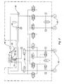
Sur la figure 7, on peut voir un système de freinage électro-hydraulique selon la
présente invention comportant un maítre-cylindre MC selon la présente invention
actionné par la tige d'actionnement 18 reliée à une pédale de frein 86, des moyens de
détection 88 du déplacement longitudinal de la tige d'actionnement 18 par exemple des
capteurs de courses, un calculateur 90 recevant les informations des moyens de
détection 88 et générant des ordres de commande pour provoquer l'actionnement de
freins 92, un générateur de pression 94 par exemple une pompe électrique recevant
l'ordre du calculateur 90 d'envoyer du liquide sous pression dans les freins 92 et des
électrovannes 96 pour interrompre la communication entre le maítre-cylindre et les
freins en fonctionnement normal, celles-ci étant ouvertes au repos et en fonctionnement
dégradé.In Figure 7, we can see an electro-hydraulic braking system according to the
present invention comprising a master cylinder MC according to the present invention
actuated by the actuating
Lors d'une action du conducteur sur la pédale de frein 86, les moyens de détection 88
envoie l'information au calculateur 90 qui génère l'ordre à la pompe 94 d'envoyer du
liquide sous pression dans les freins 92. Un réaction simulée correspondant à un circuit
de freinage classique est transmise au conducteur par la pédale de frein lui donnant la
possibilité d'ajuster son niveau de freinage.During an action of the driver on the brake pedal 86, the detection means 88
sends the information to the computer 90 which generates the order to the
Il est bien entendu qu'un maítre-cylindre comportant un seul circuit hydraulique formé d'une chambre d'alimentation et d'une chambre de pression, la chambre de pression étant raccordée à une cartouche de simulation de la sensation pédale comportant un moyen élastique selon la présente invention ne sort pas du cadre de la présente inventionIt is understood that a master cylinder comprising a single hydraulic circuit formed a supply chamber and a pressure chamber, the pressure chamber being connected to a pedal sensation simulation cartridge comprising a elastic means according to the present invention does not depart from the scope of the present invention
Nous avons bien réalisé un maítre-cylindre comportant des moyens de simulation de la sensation pédale efficace et de réalisation simple, et permettant avantageusement une adaptation simple et rapide de ces maítres-cylindres sur différents modèles de véhicule la technique et/ou une adaptation au souhait du conducteur du véhicule.We have indeed produced a master cylinder comprising means for simulating the effective pedal feel and simple implementation, and advantageously allowing a simple and quick adaptation of these master cylinders to different vehicle models the technique and / or an adaptation to the wishes of the driver of the vehicle.
La présente invention s'applique notamment à l'industrie automobile. The present invention is particularly applicable to the automotive industry.
La présente invention s'applique notamment à l'industrie du freinage pour véhicule automobile et notamment à l'industrie du freinage pour voiture particulière.The present invention applies in particular to the vehicle braking industry automotive and in particular to the braking industry for private cars.
Claims (10)
Applications Claiming Priority (2)
| Application Number | Priority Date | Filing Date | Title |
|---|---|---|---|
| FR0202440A FR2836441B1 (en) | 2002-02-25 | 2002-02-25 | MASTER CYLINDER FOR ELECTRO-HYDRAULIC BRAKING SYSTEM INCLUDING IMPROVED MEANS OF SIMULATION OF PEDAL SENSATION AND ELECTRO-HYDRAULIC BRAKING SYSTEM INCLUDING SUCH A MASTER CYLINDER |
| FR0202440 | 2002-02-25 |
Publications (2)
| Publication Number | Publication Date |
|---|---|
| EP1338488A1 true EP1338488A1 (en) | 2003-08-27 |
| EP1338488B1 EP1338488B1 (en) | 2010-07-14 |
Family
ID=27636443
Family Applications (1)
| Application Number | Title | Priority Date | Filing Date |
|---|---|---|---|
| EP03003859A Expired - Lifetime EP1338488B1 (en) | 2002-02-25 | 2003-02-20 | Master-cylinder for electro-hydraulic brake system |
Country Status (7)
| Country | Link |
|---|---|
| US (1) | US6746088B2 (en) |
| EP (1) | EP1338488B1 (en) |
| JP (1) | JP4510388B2 (en) |
| AT (1) | ATE473896T1 (en) |
| DE (1) | DE60333320D1 (en) |
| ES (1) | ES2348416T3 (en) |
| FR (1) | FR2836441B1 (en) |
Cited By (3)
| Publication number | Priority date | Publication date | Assignee | Title |
|---|---|---|---|---|
| US6746088B2 (en) * | 2002-02-25 | 2004-06-08 | Robert Bosch Gmbh | Master cylinder |
| EP2711256A4 (en) * | 2011-05-16 | 2016-05-11 | Bosch Gmbh Robert | Stroke simulator, master cylinder having same, and brake system using master cylinder |
| CN112298139A (en) * | 2020-11-09 | 2021-02-02 | 苏州海之博电子科技有限公司 | Running method of pedal simulation mechanism |
Families Citing this family (20)
| Publication number | Priority date | Publication date | Assignee | Title |
|---|---|---|---|---|
| FR2834264B1 (en) * | 2001-12-31 | 2004-02-27 | Bosch Gmbh Robert | ELECTRO-HYDRAULIC BRAKING CIRCUIT OF A VEHICLE |
| FR2836439B1 (en) * | 2002-02-25 | 2004-05-28 | Bosch Gmbh Robert | MASTER CYLINDER FOR ELECTRO-HYDRAULIC BRAKING SYSTEM INCLUDING IMPROVED MEANS OF SIMULATION OF PEDAL SENSATION AND ELECTRO-HYDRAULIC BRAKING SYSTEM INCLUDING SUCH A MASTER CYLINDER |
| JP4206887B2 (en) * | 2003-09-30 | 2009-01-14 | 株式会社日立製作所 | Master cylinder device |
| JP2005104332A (en) * | 2003-09-30 | 2005-04-21 | Hitachi Ltd | Master cylinder device |
| JP4281525B2 (en) * | 2003-11-20 | 2009-06-17 | 日産自動車株式会社 | Brake device for vehicle |
| JP4313243B2 (en) * | 2004-04-26 | 2009-08-12 | 豊田鉄工株式会社 | Electric operation device for vehicle |
| KR100987145B1 (en) * | 2004-12-08 | 2010-10-11 | 주식회사 만도 | Master cylinder for electro hydraulic brake |
| JP2008143333A (en) * | 2006-12-08 | 2008-06-26 | Toyota Motor Corp | Manipulation simulator |
| JP4835415B2 (en) * | 2006-12-08 | 2011-12-14 | トヨタ自動車株式会社 | Motion conversion transmission device |
| JP5120247B2 (en) * | 2008-12-26 | 2013-01-16 | トヨタ自動車株式会社 | Brake control device |
| US8523294B2 (en) | 2010-04-20 | 2013-09-03 | Robert Bosch Gmbh | Vehicular brake system operable in dual modes |
| US8936322B2 (en) | 2010-04-20 | 2015-01-20 | Robert Bosch Gmbh | Brake system with selector valve for selecting between two modes of operation |
| US8561401B2 (en) * | 2010-07-29 | 2013-10-22 | Robert Bosch Gmbh | Pedal feel simulator actuator and cutoff assembly |
| WO2012067196A1 (en) * | 2010-11-17 | 2012-05-24 | 本田技研工業株式会社 | Vehicle brake system |
| JP2012240601A (en) | 2011-05-23 | 2012-12-10 | Bosch Corp | Stroke simulator, master cylinder having stroke simulator, and brake system using master cylinder |
| JP2013023006A (en) | 2011-07-19 | 2013-02-04 | Bosch Corp | Stroke simulator, master cylinder with the stroke simulator, and brake system using the master cylinder |
| EP2927063B1 (en) * | 2014-04-03 | 2017-06-07 | Schaeffler Technologies GmbH & Co. KG | Pedal force simulating device |
| FR3027370B1 (en) * | 2014-10-15 | 2016-12-23 | Commissariat Energie Atomique | ASSEMBLY FOR COMPRESSION OF BALL VALVE SEAT |
| DE102016223736A1 (en) * | 2016-11-30 | 2018-05-30 | Robert Bosch Gmbh | Electro-hydraulic power-operated pressure generator |
| CN110027527B (en) * | 2018-01-12 | 2021-10-22 | 比亚迪股份有限公司 | Pedal simulator, brake-by-wire system with same and vehicle |
Citations (5)
| Publication number | Priority date | Publication date | Assignee | Title |
|---|---|---|---|---|
| DE10026309A1 (en) * | 1999-05-28 | 2000-12-21 | Aisin Seiki | Brake pressure control apparatus for vehicles, has controller to control stroke simulator to attain desired stroke during closed state of simulator cut solenoid valve when detected stroke exceeds predefined limit |
| US6192685B1 (en) * | 1997-12-22 | 2001-02-27 | Robert Bosch Gmbh | Master cylinder for motor vehicle electro-hydraulic braking installation |
| DE19952778A1 (en) * | 1999-11-03 | 2001-05-23 | Daimler Chrysler Ag | Pedal arrangement for brake-by-wire system for motor vehicles has longitudinally adjustable brake simulator actuated by pivot movement of pedal |
| WO2001068427A1 (en) * | 2000-03-15 | 2001-09-20 | Continental Teves Ag & Co. Ohg | Electrohydraulic braking system |
| WO2001072566A2 (en) * | 2000-03-27 | 2001-10-04 | Continental Teves Ag & Co. Ohg | Operating unit for an electrohydraulic braking system |
Family Cites Families (10)
| Publication number | Priority date | Publication date | Assignee | Title |
|---|---|---|---|---|
| US3141660A (en) * | 1961-03-08 | 1964-07-21 | Woodhead Monroe Ltd | Coil springs |
| JPS63176836A (en) * | 1987-01-16 | 1988-07-21 | Miura Seisakusho:Kk | Plastic coil spring |
| JPH0571481U (en) * | 1992-03-06 | 1993-09-28 | エヌ・オー・ケー・メグラスティック株式会社 | Shock absorber |
| JPH0581546U (en) * | 1992-04-07 | 1993-11-05 | 株式会社ショーワ | Front fork for motorcycle |
| JP3768574B2 (en) * | 1995-11-27 | 2006-04-19 | 三菱電機株式会社 | Elevator brake equipment |
| JPH09280282A (en) * | 1996-04-11 | 1997-10-28 | Mitsubishi Denki Bill Techno Service Kk | Brake device |
| JP3600025B2 (en) * | 1998-08-04 | 2004-12-08 | 株式会社リコー | Shape measuring device |
| JP2000135976A (en) * | 1998-10-30 | 2000-05-16 | Tokico Ltd | Brake stroke simulator |
| FR2836441B1 (en) * | 2002-02-25 | 2004-05-28 | Bosch Gmbh Robert | MASTER CYLINDER FOR ELECTRO-HYDRAULIC BRAKING SYSTEM INCLUDING IMPROVED MEANS OF SIMULATION OF PEDAL SENSATION AND ELECTRO-HYDRAULIC BRAKING SYSTEM INCLUDING SUCH A MASTER CYLINDER |
| FR2836439B1 (en) * | 2002-02-25 | 2004-05-28 | Bosch Gmbh Robert | MASTER CYLINDER FOR ELECTRO-HYDRAULIC BRAKING SYSTEM INCLUDING IMPROVED MEANS OF SIMULATION OF PEDAL SENSATION AND ELECTRO-HYDRAULIC BRAKING SYSTEM INCLUDING SUCH A MASTER CYLINDER |
-
2002
- 2002-02-25 FR FR0202440A patent/FR2836441B1/en not_active Expired - Fee Related
-
2003
- 2003-02-20 DE DE60333320T patent/DE60333320D1/en not_active Expired - Lifetime
- 2003-02-20 AT AT03003859T patent/ATE473896T1/en not_active IP Right Cessation
- 2003-02-20 ES ES03003859T patent/ES2348416T3/en not_active Expired - Lifetime
- 2003-02-20 EP EP03003859A patent/EP1338488B1/en not_active Expired - Lifetime
- 2003-02-24 US US10/373,468 patent/US6746088B2/en not_active Expired - Fee Related
- 2003-02-25 JP JP2003047812A patent/JP4510388B2/en not_active Expired - Fee Related
Patent Citations (5)
| Publication number | Priority date | Publication date | Assignee | Title |
|---|---|---|---|---|
| US6192685B1 (en) * | 1997-12-22 | 2001-02-27 | Robert Bosch Gmbh | Master cylinder for motor vehicle electro-hydraulic braking installation |
| DE10026309A1 (en) * | 1999-05-28 | 2000-12-21 | Aisin Seiki | Brake pressure control apparatus for vehicles, has controller to control stroke simulator to attain desired stroke during closed state of simulator cut solenoid valve when detected stroke exceeds predefined limit |
| DE19952778A1 (en) * | 1999-11-03 | 2001-05-23 | Daimler Chrysler Ag | Pedal arrangement for brake-by-wire system for motor vehicles has longitudinally adjustable brake simulator actuated by pivot movement of pedal |
| WO2001068427A1 (en) * | 2000-03-15 | 2001-09-20 | Continental Teves Ag & Co. Ohg | Electrohydraulic braking system |
| WO2001072566A2 (en) * | 2000-03-27 | 2001-10-04 | Continental Teves Ag & Co. Ohg | Operating unit for an electrohydraulic braking system |
Cited By (3)
| Publication number | Priority date | Publication date | Assignee | Title |
|---|---|---|---|---|
| US6746088B2 (en) * | 2002-02-25 | 2004-06-08 | Robert Bosch Gmbh | Master cylinder |
| EP2711256A4 (en) * | 2011-05-16 | 2016-05-11 | Bosch Gmbh Robert | Stroke simulator, master cylinder having same, and brake system using master cylinder |
| CN112298139A (en) * | 2020-11-09 | 2021-02-02 | 苏州海之博电子科技有限公司 | Running method of pedal simulation mechanism |
Also Published As
| Publication number | Publication date |
|---|---|
| ATE473896T1 (en) | 2010-07-15 |
| US6746088B2 (en) | 2004-06-08 |
| ES2348416T3 (en) | 2010-12-03 |
| FR2836441B1 (en) | 2004-05-28 |
| FR2836441A1 (en) | 2003-08-29 |
| EP1338488B1 (en) | 2010-07-14 |
| JP4510388B2 (en) | 2010-07-21 |
| DE60333320D1 (en) | 2010-08-26 |
| JP2004001694A (en) | 2004-01-08 |
| US20030160504A1 (en) | 2003-08-28 |
Similar Documents
| Publication | Publication Date | Title |
|---|---|---|
| EP1338488B1 (en) | Master-cylinder for electro-hydraulic brake system | |
| EP2303656B1 (en) | Braking assistance hydraulic servomotor including a motor | |
| EP1600347B1 (en) | Brake pedal simulator, master cylinder for a vehicle and method of operation of said simulator | |
| FR2860474A1 (en) | Electrical servomotor for use in e.g. car, has detection unit detecting relative movement of plunger and power assistance piston, and computer generating control to move piston such that it is closer to stable position than plunger | |
| EP1338489B1 (en) | Master cylinder for electro-hydraulic brake system | |
| EP0912382B1 (en) | Power-assisted braking device with a variable assistance ratio | |
| FR2526881A1 (en) | HYDRAULIC POWER AMPLIFIER, IN PARTICULAR FOR THE ACTUATION OF BRAKE MASTER CYLINDERS FOR THE AUTOMOTIVE | |
| EP0939713B1 (en) | Power braking device with variable assistance ratio and reduced hysteresis | |
| EP2666687B1 (en) | Brake system with electric brake servo unit and method for managing such a brake system | |
| FR2666552A1 (en) | METHOD OF ADJUSTING THE JUMP VALUE OF A PNEUMATIC BRAKE ASSIST SERVOMOTOR AND SERVOMOTOR FOR IMPLEMENTING SAID METHOD. | |
| WO1999022976A1 (en) | Master cylinder with valves having reduced clutch pedal free play | |
| EP0939715B1 (en) | Power braking system with improved hydraulic reaction | |
| EP1693264B1 (en) | Pneumatic brake booster with reduced dead zone and master brake cylinder for such a booster | |
| WO1996011828A1 (en) | Hydraulic pressure control electrovalve and its use in braking circuits | |
| EP1291257B1 (en) | Brake-feel simulator and braking system comprising such simulator | |
| EP1518770B1 (en) | Main cylinder with enhanced security | |
| WO1996022208A1 (en) | Reduced-stroke power braking device | |
| EP0991556B1 (en) | Brake power assist pneumatic booster with improved valve | |
| WO2002094626A1 (en) | Pneumatic servo brake booster with variable jump | |
| EP1522478B1 (en) | Vacuum brake booster with reduced dead stroke and brake system incorporating such booster | |
| WO2004048176A1 (en) | Master cylinder for an electrohydraulic braking system | |
| WO2002102634A2 (en) | Pneumatic brake booster with variable jump height | |
| FR2861036A1 (en) | Pneumatic actuator for motor vehicles dynamic brake control, has helical spring pulling disc support unit towards disc to allow unit displacement and disc deformation, where space is arranged between disc and unit for disc deformation |
Legal Events
| Date | Code | Title | Description |
|---|---|---|---|
| PUAI | Public reference made under article 153(3) epc to a published international application that has entered the european phase |
Free format text: ORIGINAL CODE: 0009012 |
|
| AK | Designated contracting states |
Designated state(s): AT BE BG CH CY CZ DE DK EE ES FI FR GB GR HU IE IT LI LU MC NL PT SE SI SK TR |
|
| AX | Request for extension of the european patent |
Extension state: AL LT LV MK RO |
|
| 17P | Request for examination filed |
Effective date: 20040227 |
|
| AKX | Designation fees paid |
Designated state(s): AT BE BG CH CY CZ DE DK EE ES FI FR GB GR HU IE IT LI LU MC NL PT SE SI SK TR |
|
| GRAP | Despatch of communication of intention to grant a patent |
Free format text: ORIGINAL CODE: EPIDOSNIGR1 |
|
| GRAS | Grant fee paid |
Free format text: ORIGINAL CODE: EPIDOSNIGR3 |
|
| GRAA | (expected) grant |
Free format text: ORIGINAL CODE: 0009210 |
|
| AK | Designated contracting states |
Kind code of ref document: B1 Designated state(s): AT BE BG CH CY CZ DE DK EE ES FI FR GB GR HU IE IT LI LU MC NL PT SE SI SK TR |
|
| REG | Reference to a national code |
Ref country code: GB Ref legal event code: FG4D Free format text: NOT ENGLISH |
|
| REG | Reference to a national code |
Ref country code: CH Ref legal event code: EP |
|
| REG | Reference to a national code |
Ref country code: IE Ref legal event code: FG4D |
|
| REF | Corresponds to: |
Ref document number: 60333320 Country of ref document: DE Date of ref document: 20100826 Kind code of ref document: P |
|
| REG | Reference to a national code |
Ref country code: NL Ref legal event code: VDEP Effective date: 20100714 |
|
| REG | Reference to a national code |
Ref country code: ES Ref legal event code: FG2A Effective date: 20101123 |
|
| PG25 | Lapsed in a contracting state [announced via postgrant information from national office to epo] |
Ref country code: AT Free format text: LAPSE BECAUSE OF FAILURE TO SUBMIT A TRANSLATION OF THE DESCRIPTION OR TO PAY THE FEE WITHIN THE PRESCRIBED TIME-LIMIT Effective date: 20100714 Ref country code: FI Free format text: LAPSE BECAUSE OF FAILURE TO SUBMIT A TRANSLATION OF THE DESCRIPTION OR TO PAY THE FEE WITHIN THE PRESCRIBED TIME-LIMIT Effective date: 20100714 Ref country code: NL Free format text: LAPSE BECAUSE OF FAILURE TO SUBMIT A TRANSLATION OF THE DESCRIPTION OR TO PAY THE FEE WITHIN THE PRESCRIBED TIME-LIMIT Effective date: 20100714 |
|
| REG | Reference to a national code |
Ref country code: IE Ref legal event code: FD4D |
|
| PG25 | Lapsed in a contracting state [announced via postgrant information from national office to epo] |
Ref country code: SI Free format text: LAPSE BECAUSE OF FAILURE TO SUBMIT A TRANSLATION OF THE DESCRIPTION OR TO PAY THE FEE WITHIN THE PRESCRIBED TIME-LIMIT Effective date: 20100714 Ref country code: PT Free format text: LAPSE BECAUSE OF FAILURE TO SUBMIT A TRANSLATION OF THE DESCRIPTION OR TO PAY THE FEE WITHIN THE PRESCRIBED TIME-LIMIT Effective date: 20101115 Ref country code: BG Free format text: LAPSE BECAUSE OF FAILURE TO SUBMIT A TRANSLATION OF THE DESCRIPTION OR TO PAY THE FEE WITHIN THE PRESCRIBED TIME-LIMIT Effective date: 20101014 Ref country code: CY Free format text: LAPSE BECAUSE OF FAILURE TO SUBMIT A TRANSLATION OF THE DESCRIPTION OR TO PAY THE FEE WITHIN THE PRESCRIBED TIME-LIMIT Effective date: 20100714 |
|
| PG25 | Lapsed in a contracting state [announced via postgrant information from national office to epo] |
Ref country code: SE Free format text: LAPSE BECAUSE OF FAILURE TO SUBMIT A TRANSLATION OF THE DESCRIPTION OR TO PAY THE FEE WITHIN THE PRESCRIBED TIME-LIMIT Effective date: 20100714 Ref country code: GR Free format text: LAPSE BECAUSE OF FAILURE TO SUBMIT A TRANSLATION OF THE DESCRIPTION OR TO PAY THE FEE WITHIN THE PRESCRIBED TIME-LIMIT Effective date: 20101015 |
|
| PG25 | Lapsed in a contracting state [announced via postgrant information from national office to epo] |
Ref country code: IE Free format text: LAPSE BECAUSE OF FAILURE TO SUBMIT A TRANSLATION OF THE DESCRIPTION OR TO PAY THE FEE WITHIN THE PRESCRIBED TIME-LIMIT Effective date: 20100714 Ref country code: DK Free format text: LAPSE BECAUSE OF FAILURE TO SUBMIT A TRANSLATION OF THE DESCRIPTION OR TO PAY THE FEE WITHIN THE PRESCRIBED TIME-LIMIT Effective date: 20100714 |
|
| PLBE | No opposition filed within time limit |
Free format text: ORIGINAL CODE: 0009261 |
|
| STAA | Information on the status of an ep patent application or granted ep patent |
Free format text: STATUS: NO OPPOSITION FILED WITHIN TIME LIMIT |
|
| PG25 | Lapsed in a contracting state [announced via postgrant information from national office to epo] |
Ref country code: CZ Free format text: LAPSE BECAUSE OF FAILURE TO SUBMIT A TRANSLATION OF THE DESCRIPTION OR TO PAY THE FEE WITHIN THE PRESCRIBED TIME-LIMIT Effective date: 20100714 Ref country code: SK Free format text: LAPSE BECAUSE OF FAILURE TO SUBMIT A TRANSLATION OF THE DESCRIPTION OR TO PAY THE FEE WITHIN THE PRESCRIBED TIME-LIMIT Effective date: 20100714 Ref country code: EE Free format text: LAPSE BECAUSE OF FAILURE TO SUBMIT A TRANSLATION OF THE DESCRIPTION OR TO PAY THE FEE WITHIN THE PRESCRIBED TIME-LIMIT Effective date: 20100714 |
|
| 26N | No opposition filed |
Effective date: 20110415 |
|
| REG | Reference to a national code |
Ref country code: DE Ref legal event code: R097 Ref document number: 60333320 Country of ref document: DE Effective date: 20110415 |
|
| BERE | Be: lapsed |
Owner name: ROBERT BOSCH G.M.B.H. Effective date: 20110228 |
|
| PG25 | Lapsed in a contracting state [announced via postgrant information from national office to epo] |
Ref country code: MC Free format text: LAPSE BECAUSE OF NON-PAYMENT OF DUE FEES Effective date: 20110228 |
|
| REG | Reference to a national code |
Ref country code: CH Ref legal event code: PL |
|
| PG25 | Lapsed in a contracting state [announced via postgrant information from national office to epo] |
Ref country code: LI Free format text: LAPSE BECAUSE OF NON-PAYMENT OF DUE FEES Effective date: 20110228 Ref country code: CH Free format text: LAPSE BECAUSE OF NON-PAYMENT OF DUE FEES Effective date: 20110228 |
|
| PG25 | Lapsed in a contracting state [announced via postgrant information from national office to epo] |
Ref country code: BE Free format text: LAPSE BECAUSE OF NON-PAYMENT OF DUE FEES Effective date: 20110228 |
|
| PG25 | Lapsed in a contracting state [announced via postgrant information from national office to epo] |
Ref country code: LU Free format text: LAPSE BECAUSE OF NON-PAYMENT OF DUE FEES Effective date: 20110220 |
|
| PG25 | Lapsed in a contracting state [announced via postgrant information from national office to epo] |
Ref country code: TR Free format text: LAPSE BECAUSE OF FAILURE TO SUBMIT A TRANSLATION OF THE DESCRIPTION OR TO PAY THE FEE WITHIN THE PRESCRIBED TIME-LIMIT Effective date: 20100714 |
|
| PG25 | Lapsed in a contracting state [announced via postgrant information from national office to epo] |
Ref country code: HU Free format text: LAPSE BECAUSE OF FAILURE TO SUBMIT A TRANSLATION OF THE DESCRIPTION OR TO PAY THE FEE WITHIN THE PRESCRIBED TIME-LIMIT Effective date: 20100714 |
|
| PGFP | Annual fee paid to national office [announced via postgrant information from national office to epo] |
Ref country code: FR Payment date: 20140218 Year of fee payment: 12 |
|
| REG | Reference to a national code |
Ref country code: FR Ref legal event code: ST Effective date: 20151030 |
|
| PG25 | Lapsed in a contracting state [announced via postgrant information from national office to epo] |
Ref country code: FR Free format text: LAPSE BECAUSE OF NON-PAYMENT OF DUE FEES Effective date: 20150302 |
|
| PGFP | Annual fee paid to national office [announced via postgrant information from national office to epo] |
Ref country code: IT Payment date: 20160222 Year of fee payment: 14 Ref country code: ES Payment date: 20160223 Year of fee payment: 14 |
|
| PGFP | Annual fee paid to national office [announced via postgrant information from national office to epo] |
Ref country code: GB Payment date: 20160222 Year of fee payment: 14 |
|
| PGFP | Annual fee paid to national office [announced via postgrant information from national office to epo] |
Ref country code: DE Payment date: 20170427 Year of fee payment: 15 |
|
| GBPC | Gb: european patent ceased through non-payment of renewal fee |
Effective date: 20170220 |
|
| PG25 | Lapsed in a contracting state [announced via postgrant information from national office to epo] |
Ref country code: IT Free format text: LAPSE BECAUSE OF NON-PAYMENT OF DUE FEES Effective date: 20170220 Ref country code: GB Free format text: LAPSE BECAUSE OF NON-PAYMENT OF DUE FEES Effective date: 20170220 |
|
| REG | Reference to a national code |
Ref country code: ES Ref legal event code: FD2A Effective date: 20180706 |
|
| REG | Reference to a national code |
Ref country code: DE Ref legal event code: R119 Ref document number: 60333320 Country of ref document: DE |
|
| PG25 | Lapsed in a contracting state [announced via postgrant information from national office to epo] |
Ref country code: ES Free format text: LAPSE BECAUSE OF NON-PAYMENT OF DUE FEES Effective date: 20170221 |
|
| PG25 | Lapsed in a contracting state [announced via postgrant information from national office to epo] |
Ref country code: DE Free format text: LAPSE BECAUSE OF NON-PAYMENT OF DUE FEES Effective date: 20180901 |