EP1336735B1 - Kühlsystem für eine Brennkraftmaschine - Google Patents
Kühlsystem für eine Brennkraftmaschine Download PDFInfo
- Publication number
- EP1336735B1 EP1336735B1 EP02450261A EP02450261A EP1336735B1 EP 1336735 B1 EP1336735 B1 EP 1336735B1 EP 02450261 A EP02450261 A EP 02450261A EP 02450261 A EP02450261 A EP 02450261A EP 1336735 B1 EP1336735 B1 EP 1336735B1
- Authority
- EP
- European Patent Office
- Prior art keywords
- charge
- air
- cooling system
- compressor
- cooling
- Prior art date
- Legal status (The legal status is an assumption and is not a legal conclusion. Google has not performed a legal analysis and makes no representation as to the accuracy of the status listed.)
- Expired - Lifetime
Links
- 238000001816 cooling Methods 0.000 title claims description 43
- 238000002485 combustion reaction Methods 0.000 title claims description 18
- 239000002826 coolant Substances 0.000 claims description 7
- 230000008878 coupling Effects 0.000 claims description 7
- 238000010168 coupling process Methods 0.000 claims description 7
- 238000005859 coupling reaction Methods 0.000 claims description 7
- 230000005484 gravity Effects 0.000 claims description 5
- 238000011144 upstream manufacturing Methods 0.000 claims description 5
- 238000005192 partition Methods 0.000 claims description 2
- 239000007788 liquid Substances 0.000 description 6
- XAGFODPZIPBFFR-UHFFFAOYSA-N aluminium Chemical compound [Al] XAGFODPZIPBFFR-UHFFFAOYSA-N 0.000 description 2
- 229910052782 aluminium Inorganic materials 0.000 description 2
- 239000000463 material Substances 0.000 description 2
- 239000000725 suspension Substances 0.000 description 2
- 230000005540 biological transmission Effects 0.000 description 1
- 239000003990 capacitor Substances 0.000 description 1
- 238000006243 chemical reaction Methods 0.000 description 1
- 230000006378 damage Effects 0.000 description 1
- 238000013016 damping Methods 0.000 description 1
- 230000008030 elimination Effects 0.000 description 1
- 238000003379 elimination reaction Methods 0.000 description 1
- 238000012423 maintenance Methods 0.000 description 1
- 230000001105 regulatory effect Effects 0.000 description 1
- 230000008961 swelling Effects 0.000 description 1
Images


Classifications
-
- F—MECHANICAL ENGINEERING; LIGHTING; HEATING; WEAPONS; BLASTING
- F02—COMBUSTION ENGINES; HOT-GAS OR COMBUSTION-PRODUCT ENGINE PLANTS
- F02B—INTERNAL-COMBUSTION PISTON ENGINES; COMBUSTION ENGINES IN GENERAL
- F02B29/00—Engines characterised by provision for charging or scavenging not provided for in groups F02B25/00, F02B27/00 or F02B33/00 - F02B39/00; Details thereof
- F02B29/04—Cooling of air intake supply
- F02B29/045—Constructional details of the heat exchangers, e.g. pipes, plates, ribs, insulation, materials, or manufacturing and assembly
- F02B29/0475—Constructional details of the heat exchangers, e.g. pipes, plates, ribs, insulation, materials, or manufacturing and assembly the intake air cooler being combined with another device, e.g. heater, valve, compressor, filter or EGR cooler, or being assembled on a special engine location
-
- F—MECHANICAL ENGINEERING; LIGHTING; HEATING; WEAPONS; BLASTING
- F01—MACHINES OR ENGINES IN GENERAL; ENGINE PLANTS IN GENERAL; STEAM ENGINES
- F01P—COOLING OF MACHINES OR ENGINES IN GENERAL; COOLING OF INTERNAL-COMBUSTION ENGINES
- F01P3/00—Liquid cooling
- F01P3/18—Arrangements or mounting of liquid-to-air heat-exchangers
-
- F—MECHANICAL ENGINEERING; LIGHTING; HEATING; WEAPONS; BLASTING
- F02—COMBUSTION ENGINES; HOT-GAS OR COMBUSTION-PRODUCT ENGINE PLANTS
- F02B—INTERNAL-COMBUSTION PISTON ENGINES; COMBUSTION ENGINES IN GENERAL
- F02B29/00—Engines characterised by provision for charging or scavenging not provided for in groups F02B25/00, F02B27/00 or F02B33/00 - F02B39/00; Details thereof
- F02B29/04—Cooling of air intake supply
- F02B29/0406—Layout of the intake air cooling or coolant circuit
- F02B29/0412—Multiple heat exchangers arranged in parallel or in series
-
- F—MECHANICAL ENGINEERING; LIGHTING; HEATING; WEAPONS; BLASTING
- F02—COMBUSTION ENGINES; HOT-GAS OR COMBUSTION-PRODUCT ENGINE PLANTS
- F02B—INTERNAL-COMBUSTION PISTON ENGINES; COMBUSTION ENGINES IN GENERAL
- F02B29/00—Engines characterised by provision for charging or scavenging not provided for in groups F02B25/00, F02B27/00 or F02B33/00 - F02B39/00; Details thereof
- F02B29/04—Cooling of air intake supply
- F02B29/0406—Layout of the intake air cooling or coolant circuit
- F02B29/0425—Air cooled heat exchangers
- F02B29/0431—Details or means to guide the ambient air to the heat exchanger, e.g. having a fan, flaps, a bypass or a special location in the engine compartment
-
- B—PERFORMING OPERATIONS; TRANSPORTING
- B60—VEHICLES IN GENERAL
- B60K—ARRANGEMENT OR MOUNTING OF PROPULSION UNITS OR OF TRANSMISSIONS IN VEHICLES; ARRANGEMENT OR MOUNTING OF PLURAL DIVERSE PRIME-MOVERS IN VEHICLES; AUXILIARY DRIVES FOR VEHICLES; INSTRUMENTATION OR DASHBOARDS FOR VEHICLES; ARRANGEMENTS IN CONNECTION WITH COOLING, AIR INTAKE, GAS EXHAUST OR FUEL SUPPLY OF PROPULSION UNITS IN VEHICLES
- B60K11/00—Arrangement in connection with cooling of propulsion units
- B60K11/02—Arrangement in connection with cooling of propulsion units with liquid cooling
-
- F—MECHANICAL ENGINEERING; LIGHTING; HEATING; WEAPONS; BLASTING
- F01—MACHINES OR ENGINES IN GENERAL; ENGINE PLANTS IN GENERAL; STEAM ENGINES
- F01P—COOLING OF MACHINES OR ENGINES IN GENERAL; COOLING OF INTERNAL-COMBUSTION ENGINES
- F01P3/00—Liquid cooling
- F01P3/18—Arrangements or mounting of liquid-to-air heat-exchangers
- F01P2003/182—Arrangements or mounting of liquid-to-air heat-exchangers with multiple heat-exchangers
-
- F—MECHANICAL ENGINEERING; LIGHTING; HEATING; WEAPONS; BLASTING
- F01—MACHINES OR ENGINES IN GENERAL; ENGINE PLANTS IN GENERAL; STEAM ENGINES
- F01P—COOLING OF MACHINES OR ENGINES IN GENERAL; COOLING OF INTERNAL-COMBUSTION ENGINES
- F01P3/00—Liquid cooling
- F01P3/18—Arrangements or mounting of liquid-to-air heat-exchangers
- F01P2003/185—Arrangements or mounting of liquid-to-air heat-exchangers arranged in parallel
-
- F—MECHANICAL ENGINEERING; LIGHTING; HEATING; WEAPONS; BLASTING
- F01—MACHINES OR ENGINES IN GENERAL; ENGINE PLANTS IN GENERAL; STEAM ENGINES
- F01P—COOLING OF MACHINES OR ENGINES IN GENERAL; COOLING OF INTERNAL-COMBUSTION ENGINES
- F01P3/00—Liquid cooling
- F01P3/18—Arrangements or mounting of liquid-to-air heat-exchangers
- F01P2003/187—Arrangements or mounting of liquid-to-air heat-exchangers arranged in series
-
- F—MECHANICAL ENGINEERING; LIGHTING; HEATING; WEAPONS; BLASTING
- F01—MACHINES OR ENGINES IN GENERAL; ENGINE PLANTS IN GENERAL; STEAM ENGINES
- F01P—COOLING OF MACHINES OR ENGINES IN GENERAL; COOLING OF INTERNAL-COMBUSTION ENGINES
- F01P2060/00—Cooling circuits using auxiliaries
- F01P2060/02—Intercooler
-
- F—MECHANICAL ENGINEERING; LIGHTING; HEATING; WEAPONS; BLASTING
- F02—COMBUSTION ENGINES; HOT-GAS OR COMBUSTION-PRODUCT ENGINE PLANTS
- F02B—INTERNAL-COMBUSTION PISTON ENGINES; COMBUSTION ENGINES IN GENERAL
- F02B37/00—Engines characterised by provision of pumps driven at least for part of the time by exhaust
- F02B37/013—Engines characterised by provision of pumps driven at least for part of the time by exhaust with exhaust-driven pumps arranged in series
-
- Y—GENERAL TAGGING OF NEW TECHNOLOGICAL DEVELOPMENTS; GENERAL TAGGING OF CROSS-SECTIONAL TECHNOLOGIES SPANNING OVER SEVERAL SECTIONS OF THE IPC; TECHNICAL SUBJECTS COVERED BY FORMER USPC CROSS-REFERENCE ART COLLECTIONS [XRACs] AND DIGESTS
- Y02—TECHNOLOGIES OR APPLICATIONS FOR MITIGATION OR ADAPTATION AGAINST CLIMATE CHANGE
- Y02T—CLIMATE CHANGE MITIGATION TECHNOLOGIES RELATED TO TRANSPORTATION
- Y02T10/00—Road transport of goods or passengers
- Y02T10/10—Internal combustion engine [ICE] based vehicles
- Y02T10/12—Improving ICE efficiencies
Definitions
- the invention relates to a cooling system for an internal combustion engine with two-stage Charging, with a charge air line, in which a first compressor of a first exhaust gas turbocharger and downstream of this a second compressor of a second exhaust gas turbocharger is arranged, wherein between the first and the second compressor, a first intercooler and downstream of the second compressor a second intercooler is arranged.
- JP 62-085123 A is a cooling system of an internal combustion engine with two-stage Charging the aforementioned type known. Through the first intercooler between the first and the second compressor, the charge air temperature be lowered so far that no thermal overload of the second compressor occurs. In the known cooling system, however, is no Regulation of the state of charge as a function of the operating state provided. This has the disadvantage that the turbocharger is not always with optimum efficiency can be operated. A similar cooling system is also from the DE 199 48 220 A1.
- US 5,492,167 A discloses a cooling system with a liquid cooler and a charge air cooler, which can be folded in front of the liquid cooler.
- JP 2000-120 439 A shows a radiator arrangement for an internal combustion engine, in which an intercooler is arranged in front of a liquid cooler.
- the object of the invention is a powerful cooling system for an internal combustion engine to develop, which is space-saving, as well as little weight, has few components and a long service life.
- this is achieved in that at least one of the two Intercooler, viewed in the direction of flow of the cooling air, upstream of the Coolant cooler is arranged, and that the second intercooler over or is arranged next to the first intercooler. Because of the intercooler upstream of the liquid cooler, space can be saved and a particularly good cooling of the charge air can be achieved.
- the first intercooler is achieved that the Charge air temperature between the two compressors drops so far that too the second compressor is a conventional cast aluminum compressor wheel can be used without too high inlet temperature in the second compressor to affect the life of the compressor wheel. Consequently Also, the problem of low-cycle fatigue of the compressor wheel is prevented.
- At at least one intercooler preferably at the first intercooler, radiator inlet and radiator outlet on the same side - relative to one in direction the inflowing cooling air through the center of gravity of the intercooler running Plateau - are arranged. It is particularly advantageous if at least one intercooler, preferably the first intercooler, a preferably through the center of gravity extending partition between incoming and exiting charge air flow, so that a substantially U-shaped Flow path for the charge air flowing through the charge air formed is. This allows the charge air line between the first intercooler and the second compressor are made very short, thereby material can be saved and flow losses can be reduced.
- the consisting of the first and second intercooler and the coolant radiator Cooler group is engine-trained.
- the motor-fixed arrangement of the radiator group allows small distances between the components, as relative movements do not need to be considered.
- the cooling system can be very compact being held.
- flexible elements in the charge air ducts are largely dispensed with, which is advantageous to the Costs and maintenance intensity.
- flexible conduit elements such as rubber cables with low fatigue strength be waived.
- the suspension of the radiator group in a vehicle frame About rubber bearings deleted.
- the engine-fixed radiator group will be installed in the Vehicle together with the internal combustion engine and the transmission in one elastic drive unit suspension lifted. Due to the elimination of the flexible There are also no gas reaction forces in the charge air ducts on the individual radiators and pipes more. Thus, separate support elements or the like omitted.
- radiator group is fixed to the vehicle frame is trained.
- first compressor, first intercooler, second compressor and second intercooler and an inlet header elastic conduit elements are arranged.
- the second exhaust gas turbocharger preferably on the exhaust side, regulated bypassed. Due to the bypassability of the second compressor - the high pressure compressor - by means of the bypass line and at least one or more valves at high exhaust gas levels - at high loads and engine speeds - it is possible to use both turbochargers operate in optimal operating ranges, which is a significant efficiency advantage opposite unregulated serial charging systems brings.
- the small high-pressure turbine compressor combination turns even at low Exhaust gas levels rise rapidly. This will give a very quick response of the Internal combustion engine reached.
- a preferably axial fan is provided, which is driven to control the cooling air requirement via a switchable coupling is.
- the drive power can be saved with low cooling air requirement become.
- the coupling has a visco-thermal element.
- the clutch externally via at least a cooling air temperature sensor and an electronic control unit is activated becomes.
- the internal combustion engine 1 has a two-stage supercharging with a first exhaust gas turbocharger 2 and a second exhaust gas turbocharger 3.
- a first exhaust gas turbocharger 2 In the charge air line 4 is the first compressor 5 of the first exhaust gas turbocharger 2 and downstream this second compressor 6 of the second exhaust gas turbocharger 3 is arranged.
- the first exhaust gas turbine of the first exhaust gas turbocharger 2 and with reference numeral 8 the second exhaust gas turbine of the second exhaust gas turbocharger 3rd designated.
- the first-stage first exhaust gas turbocharger has a large volume, the two-stage second turbocharger 3 designed small volume.
- the second exhaust gas turbine 8 of the second exhaust gas turbocharger 3 can by means of a bypassed at least one valve bypass device 9 are bypassed.
- first intercooler 10 is arranged between the first compressor 5 and the second compressor 6 is in the charge air line 4, a first intercooler 10 is arranged.
- second intercooler 11 is provided downstream of the second compressor 6.
- the intercooler 10, 11 are part of a cooler group 12, which is also the coolant radiator 13 belongs.
- the first and the second intercooler 10, 11 are - in the direction indicated by the arrows L direction of flow of the air - disposed upstream of the coolant cooler 13.
- the second intercooler 11 is positioned above the first intercooler 10. This makes possible a very compact design.
- the upstream of the coolant radiator 13 arranged with respect to the cooling air L, via a switchable coupling 17a driven fan 17 is as an axial fan executed.
- the switchable coupling 17a can be a visco-thermal element include and be self-regulating executed.
- the Clutch 17a externally via a cooling air temperature sensor 17b and a control unit ECU are controlled.
- Reference numeral 18 denotes the fan housing.
- the radiator group 12 is designed to be fixed to the vehicle, whereby in each case between the sections of the charge air line 4 between the first Compressor 5 and first intercooler 10, second compressor 6, second intercooler 11 and an inlet header 20 elastic elements 14 are provided are.
- the charge air flows according to the arrows P 2 , P 3 , P 4 from the radiator inlet 15 to the radiator outlet 16 and is thereby cooled between.
- the charge air passes according to the arrow P 5 to the second compressor 6 of the second exhaust gas turbocharger 3.
- the second compressor 6 designed as a high-pressure stage, the charge air is further compressed and guided according to the arrow P 6 to the second charge air cooler 11, where a further temperature reduction of the charge air takes place.
- the charge air flows through the second intercooler 11 from the second radiator inlet 25 to the second radiator outlet 26 in the transverse direction according to the arrow P 7 and leaves the second intercooler 11 on the second charge air inlet 25 opposite side of the plateau 22.
- the second intercooler 11 leaving the charge air P 8 led to the inlet header 20 and on to the individual cylinders 21.
- radiator inlet 15 and radiator outlet 16 of first intercooler 10 are arranged on the same side of a plateau 22 extending through the center of gravity S of intercooler 10 and oriented in the direction of flow of cooling air L.
- the charge air entering the first intercooler 10 according to the arrow P 2 and exiting in accordance with the arrow P 4 is - apart from a passage 24 on the side opposite the radiator inlet 15 and the radiator outlet 16 - separated from each other.
- the first charge air cooler 10 flows through the charge air in a U-shaped manner in the transverse direction, as indicated by the arrow P 3 . This has the advantage that the charge air line 4a between the first charge air cooler 10 and the second compressor 6 can be kept short.
Description
- Fig. 1
- die erfindungsgemäße Brennkraftmaschine in einer Ausführungsvariante in einer Schrägansicht,
- Fig. 2
- die Brennkraftmaschine in einem Schnitt gemäß der Linie II-II in Fig. 3,
- Fig. 3
- die Brennkraftmaschine in einer Stirnansicht,
- Fig. 4
- die Brennkraftmaschine in einer Seitenansicht,
- Fig. 5
- die Brennkraftmaschine in einer Draufsicht,
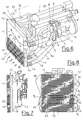
- Fig. 6
- die erfindungsgemäße Brennkraftmaschine in einer zweiten Ausführungsvariante in einer Schrägansicht,
- Fig. 7
- die Brennkraftmaschine in einem Schnitt gemäß der Linie VII-VII in Fig. 8,
- Fig. 8
- die Brennkraftmaschine in einer Vorderansicht.
Claims (10)
- Kühlsystem für eine Brennkraftmaschine (1) mit zweistufiger Aufladung, mit einer Ladeluftleitung (4), in welcher ein erster Verdichter (5) eines ersten Abgasturboladers (2) und stromabwärts dieses ein zweiter Verdichter (6) eines zweiten Abgasturboladers (3) angeordnet ist, wobei zwischen dem ersten und dem zweiten Verdichter (5, 6) ein erster Ladeluftkühler (10) und stromabwärts des zweiten Verdichters (6) ein zweiter Ladeluftkühler (11) angeordnet ist, dadurch gekennzeichnet, dass zumindest einer der beiden Ladeluftkühler (10, 11), in Anströmrichtung der Kühlluft (L) betrachtet, stromaufwärts eines Kühlmittelkühlers (13) angeordnet ist, und dass der zweite Ladeluftkühler (11) über oder neben dem ersten Ladeluftkühler (10) angeordnet ist.
- Kühlsystem nach Anspruch 1, dadurch gekennzeichnet, dass bei zumindest einem Ladeluftkühler (10, 11), vorzugsweise beim ersten Ladeluftkühler (10), Kühlereintritt (15) und Kühleraustritt (16) auf der selben Seite - bezogen auf eine Richtung der anströmenden Kühlluft (L) durch den Schwerpunkt (S) des Ladeluftkühlers (10) verlaufende Hochebene (22) - angeordnet sind.
- Kühlsystem nach Anspruch 1 oder 2, dadurch gekennzeichnet, dass zumindest ein Ladeluftkühler (10, 11), vorzugsweise der erste Ladeluftkühler (10), eine vorzugsweise durch den Schwerpunkt (S) verlaufende Trennwand (23) zwischen eintretendem und austretendem Ladeluftstrom (P2, P4) aufweist, so dass ein im Wesentlichen U-förmiger Strömungsweg (P3) für die den Ladeluftkühler durchströmende Ladeluft gebildet ist.
- Kühlsystem nach einem der Ansprüche 1 bis 3, dadurch gekennzeichnet, dass die aus erstem und zweitem Ladeluftkühler (10, 11) und dem Kühlmittelkühler (13) bestehende Kühlergruppe (12) motorfest ausgebildet ist.
- Kühlsystem nach einem der Ansprüche 1 bis 3, dadurch gekennzeichnet, dass die Kühlergruppe (12) fahrzeugrahmenfest ausgebildet ist.
- Kühlsystem nach einem der Ansprüche 1 bis 5, dadurch gekennzeichnet, dass in der Ladeluftleitung (4) zwischen erstem Verdichter (5), erstem Ladeluftkühler (10), zweitem Verdichter (6), zweiten Ladeluftkühler (11) und einem Einlasssammler (20) elastische Leitungselemente (14) angeordnet sind.
- Kühlsystem nach einem der Ansprüche 1 bis 6, dadurch gekennzeichnet, dass der zweite Abgasturbolader (3), vorzugsweise abgasseitig, geregelt umgehbar ist.
- Kühlsystem nach einem der Ansprüche 1 bis 7 mit einem Lüfter (17) zur Erzeugung eines Kühlluftstroms (2), dadurch gekennzeichnet, dass der vorzugsweise axiale Lüfter (17) über eine schaltbare Kupplung (17a) angetrieben ist.
- Kühlsystem nach Anspruch 8, dadurch gekennzeichnet, dass die schaltbare Kupplung (17a) ein Visko-Thermo-Element aufweist.
- Kühlsystem nach Anspruch 8, dadurch gekennzeichnet, dass die Kupplung (17a) extern über zumindest einen Kühllufttemperaturgeber (17b) und eine elektronische Steuereinheit (ECU) ansteuerbar ist.
Applications Claiming Priority (3)
| Application Number | Priority Date | Filing Date | Title |
|---|---|---|---|
| AT0009302U AT6051U1 (de) | 2002-02-14 | 2002-02-14 | Kühlsystem für eine brennkraftmaschine |
| AT932002 | 2002-02-14 | ||
| AT932002U | 2002-02-14 |
Publications (3)
| Publication Number | Publication Date |
|---|---|
| EP1336735A2 EP1336735A2 (de) | 2003-08-20 |
| EP1336735A3 EP1336735A3 (de) | 2004-06-30 |
| EP1336735B1 true EP1336735B1 (de) | 2005-10-19 |
Family
ID=3481311
Family Applications (1)
| Application Number | Title | Priority Date | Filing Date |
|---|---|---|---|
| EP02450261A Expired - Lifetime EP1336735B1 (de) | 2002-02-14 | 2002-11-14 | Kühlsystem für eine Brennkraftmaschine |
Country Status (5)
| Country | Link |
|---|---|
| US (1) | US6782849B2 (de) |
| EP (1) | EP1336735B1 (de) |
| JP (1) | JP2003239752A (de) |
| AT (1) | AT6051U1 (de) |
| DE (1) | DE50204591D1 (de) |
Cited By (5)
| Publication number | Priority date | Publication date | Assignee | Title |
|---|---|---|---|---|
| DE102006022493A1 (de) * | 2006-05-13 | 2007-11-15 | Volkswagen Ag | Verbrennungsluftansaugsystem für eine Brennkraftmaschine |
| US7310946B2 (en) | 2003-07-31 | 2007-12-25 | Behr Gmbh & Co. Kg | Circuit arrangement for cooling charge air and method for operating a circuit arrangement of this type |
| DE10309808B4 (de) * | 2002-03-14 | 2008-05-08 | Avl List Gmbh | Kühlsystem für eine Brennkraftmaschine mit zweistufiger Aufladung |
| DE102010029691A1 (de) * | 2010-06-03 | 2011-12-08 | Mtu Friedrichshafen Gmbh | Brennkraftmaschine und Ladefluid-Kühler |
| CN103147842A (zh) * | 2013-03-20 | 2013-06-12 | 重庆科克发动机技术有限公司 | 一种涡轮增压发动机空气分配管 |
Families Citing this family (27)
| Publication number | Priority date | Publication date | Assignee | Title |
|---|---|---|---|---|
| CN101027473A (zh) * | 2004-09-21 | 2007-08-29 | 沃尔沃拉斯特瓦格纳公司 | 用于内燃机涡轮增压器系统的管路 |
| US7100584B1 (en) | 2004-10-14 | 2006-09-05 | Brunswick Corporation | Method and apparatus for controlling an internal combustion engine |
| DE102005012307A1 (de) * | 2005-03-17 | 2006-09-21 | Daimlerchrysler Ag | Wärmetauscher für ein Kraftfahrzeug |
| FR2933041B1 (fr) * | 2008-06-27 | 2010-12-24 | Peugeot Citroen Automobiles Sa | Ensemble comportant un echangeur thermique basculant |
| JP5029547B2 (ja) * | 2008-09-15 | 2012-09-19 | 株式会社デンソー | 吸気冷却システム |
| JP5331722B2 (ja) * | 2010-02-05 | 2013-10-30 | 株式会社日立製作所 | 車両の電気駆動システム |
| DE102010010398A1 (de) * | 2010-03-05 | 2011-09-08 | GM Global Technology Operations LLC , (n. d. Ges. d. Staates Delaware) | Frontstruktur eines Kraftfahrzeugs |
| DE102010013381A1 (de) * | 2010-03-30 | 2011-10-06 | Gm Global Technology Operations Llc (N.D.Ges.D. Staates Delaware) | Vorderbau für ein Kraftfahrzeug |
| DE102010018356A1 (de) * | 2010-04-27 | 2011-12-29 | Man Truck & Bus Ag | Anordnung einer Ladeluftleitung an einer Brennkraftmaschine |
| JP5471899B2 (ja) | 2010-06-30 | 2014-04-16 | マツダ株式会社 | 車両用エンジンのターボ過給機の潤滑装置 |
| JP5499953B2 (ja) | 2010-06-30 | 2014-05-21 | マツダ株式会社 | 車両用エンジンのターボ過給装置 |
| JP5494294B2 (ja) | 2010-06-30 | 2014-05-14 | マツダ株式会社 | 車両用エンジンのターボ過給機の冷却装置 |
| DE102011075617B4 (de) * | 2011-05-10 | 2013-05-08 | Mtu Friedrichshafen Gmbh | Verfahren zur Führung einer Ladeluft, Anschlusskasten für eine Kühleranordnung und Kühleranordnung für eine Brennkraftmaschine und Brennkraftmaschine mit einer zweistufigen Aufladung |
| JP5963496B2 (ja) | 2012-03-28 | 2016-08-03 | ヤンマー株式会社 | エンジン |
| JP5983453B2 (ja) * | 2013-02-08 | 2016-08-31 | 株式会社デンソー | 吸気冷却装置 |
| JP6077100B2 (ja) | 2013-02-21 | 2017-02-08 | 三菱重工業株式会社 | 流体機械及びこれを備えた流体機械システム |
| WO2014200580A1 (en) * | 2013-06-12 | 2014-12-18 | United Technologies Corporation | Fuel/oil manifold |
| CN105960514A (zh) * | 2014-01-30 | 2016-09-21 | 洋马株式会社 | 发动机 |
| DE102016223730A1 (de) * | 2016-11-30 | 2018-05-30 | Bayerische Motoren Werke Aktiengesellschaft | Antriebssystem für ein Kraftfahrzeug sowie Kraftfahrzeug mit dem Antriebssystem |
| US10563925B2 (en) * | 2017-07-12 | 2020-02-18 | Caterpillar Inc. | Cooling assembly for service vehicle |
| JP2019027403A (ja) * | 2017-08-02 | 2019-02-21 | 日野自動車株式会社 | 二段過給システム |
| JP6849093B2 (ja) * | 2017-10-11 | 2021-03-24 | マツダ株式会社 | 過給機付エンジン |
| DE102017219939A1 (de) * | 2017-11-09 | 2019-05-09 | Volkswagen Aktiengesellschaft | Kühlkreislauf für eine Antriebseinheit eines Kraftfahrzeuges |
| GB2576883B (en) * | 2018-09-04 | 2021-06-16 | Caterpillar Motoren Gmbh & Co | Two-stage turbocharged internal combustion engine |
| US11560829B2 (en) | 2020-01-02 | 2023-01-24 | Caterpillar Inc. | Recirculation system for a power system that includes a plurality of turbochargers |
| JP7270087B2 (ja) * | 2020-09-25 | 2023-05-09 | ヤンマーパワーテクノロジー株式会社 | エンジン装置 |
| JP7035146B2 (ja) * | 2020-09-25 | 2022-03-14 | ヤンマーパワーテクノロジー株式会社 | エンジン装置 |
Family Cites Families (20)
| Publication number | Priority date | Publication date | Assignee | Title |
|---|---|---|---|---|
| GB182787A (de) * | 1921-07-09 | 1923-05-10 | Augustus Rateau | |
| US4062188A (en) * | 1976-03-31 | 1977-12-13 | Wallace Murray Corporation | Turbocharger system for an internal combustion engine |
| US4213426A (en) | 1978-11-09 | 1980-07-22 | General Motors Corporation | Shrouding for engine mounted cooling fan |
| JPS60101223A (ja) * | 1983-11-08 | 1985-06-05 | Yanmar Diesel Engine Co Ltd | 2段過給式内燃機関 |
| JPH0247228Y2 (de) | 1985-09-14 | 1990-12-12 | ||
| JPS6285123A (ja) | 1985-10-11 | 1987-04-18 | Mitsubishi Heavy Ind Ltd | 2段過給タ−ボコンパウンド内燃機関 |
| EP0334206B1 (de) | 1988-03-19 | 1992-06-17 | Mazda Motor Corporation | Zufuhrluftkontrollverfahren für Brennkraftmaschinen |
| US5063744A (en) | 1988-10-06 | 1991-11-12 | Toyota Jidosha Kabushiki Kaisha | Actuator for controlling intake pressure in sequential turbo-system |
| SE467634B (sv) | 1990-05-15 | 1992-08-17 | Volvo Ab | Anordning vid turboreglering |
| JPH0450433A (ja) | 1990-06-20 | 1992-02-19 | Toyota Motor Corp | 直列2段過給内燃機関の排気ガス再循環装置 |
| DE4101708C2 (de) * | 1991-01-22 | 1994-12-08 | Man Nutzfahrzeuge Ag | Brennkraftmaschine mit zweistufiger Ladeluftkühlung |
| US5492167A (en) | 1992-07-15 | 1996-02-20 | Glesmann; Herbert C. | Latchably pivotably-coupled heat-exchangers for motor-home and related vehicles |
| DE9213450U1 (de) | 1992-10-06 | 1993-01-07 | Cummins Engine Co. Ltd., New Malden, Surrey, Gb | |
| US6029345A (en) | 1995-11-13 | 2000-02-29 | Alliedsignal Inc. | Radiator, charge air cooler and condenser mounting method |
| DE19928193A1 (de) | 1998-07-09 | 2000-01-13 | Behr Gmbh & Co | Anordnung von Wärmeübertragern, insbesondere in einem Kraftfahrzeug |
| JP3481871B2 (ja) | 1998-10-14 | 2003-12-22 | 日立建機株式会社 | 建設機械 |
| US6129056A (en) * | 1999-08-23 | 2000-10-10 | Case Corporation | Cooling system for work vehicle |
| DE19948220A1 (de) | 1999-10-06 | 2001-01-25 | Daimler Chrysler Ag | Brennkraftmaschine mit zwei Abgasturboladern |
| DE10018090A1 (de) * | 2000-04-12 | 2001-11-29 | Modine Mfg Co | Ventilatorantrieb |
| JP3783527B2 (ja) * | 2000-05-23 | 2006-06-07 | いすゞ自動車株式会社 | 2段過給システム |
-
2002
- 2002-02-14 AT AT0009302U patent/AT6051U1/de not_active IP Right Cessation
- 2002-11-11 JP JP2002326207A patent/JP2003239752A/ja active Pending
- 2002-11-14 EP EP02450261A patent/EP1336735B1/de not_active Expired - Lifetime
- 2002-11-14 DE DE50204591T patent/DE50204591D1/de not_active Expired - Lifetime
- 2002-11-21 US US10/300,766 patent/US6782849B2/en not_active Expired - Lifetime
Cited By (6)
| Publication number | Priority date | Publication date | Assignee | Title |
|---|---|---|---|---|
| DE10309808B4 (de) * | 2002-03-14 | 2008-05-08 | Avl List Gmbh | Kühlsystem für eine Brennkraftmaschine mit zweistufiger Aufladung |
| US7310946B2 (en) | 2003-07-31 | 2007-12-25 | Behr Gmbh & Co. Kg | Circuit arrangement for cooling charge air and method for operating a circuit arrangement of this type |
| DE102006022493A1 (de) * | 2006-05-13 | 2007-11-15 | Volkswagen Ag | Verbrennungsluftansaugsystem für eine Brennkraftmaschine |
| DE102010029691A1 (de) * | 2010-06-03 | 2011-12-08 | Mtu Friedrichshafen Gmbh | Brennkraftmaschine und Ladefluid-Kühler |
| DE102010029691B4 (de) * | 2010-06-03 | 2012-02-16 | Mtu Friedrichshafen Gmbh | Brennkraftmaschine und Ladefluid-Kühler |
| CN103147842A (zh) * | 2013-03-20 | 2013-06-12 | 重庆科克发动机技术有限公司 | 一种涡轮增压发动机空气分配管 |
Also Published As
| Publication number | Publication date |
|---|---|
| JP2003239752A (ja) | 2003-08-27 |
| US6782849B2 (en) | 2004-08-31 |
| DE50204591D1 (de) | 2006-03-02 |
| EP1336735A2 (de) | 2003-08-20 |
| US20030150408A1 (en) | 2003-08-14 |
| EP1336735A3 (de) | 2004-06-30 |
| AT6051U1 (de) | 2003-03-25 |
Similar Documents
| Publication | Publication Date | Title |
|---|---|---|
| EP1336735B1 (de) | Kühlsystem für eine Brennkraftmaschine | |
| EP2267285B1 (de) | Abgasbaugruppe | |
| DE102006053191B4 (de) | Ladeluftkühlerkondensatablaufsystem | |
| EP1543232B1 (de) | Brennkraftmaschine mit einem verdichter im ansaugtrakt | |
| EP1995425B1 (de) | Integriertes Auflademodul | |
| WO2007028591A2 (de) | Kühlsystem für ein kraftfahrzeug | |
| WO2007093367A1 (de) | Verdichter für eine brennkraftmaschine | |
| WO2007124843A1 (de) | Abgasturbolader in einer brennkraftmaschine | |
| DE102008039086A1 (de) | Abgasturbolader für eine Brennkraftmaschine eines Kraftfahrzeugs | |
| DE102014217333B4 (de) | Mehrstufiges Turboladersystem für einen Verbrennungsmotor | |
| DE102010045202A1 (de) | Turbolader und damit versehenes Lufteinlasssystem und Verfahren zu seiner Herstellung und Verwendung | |
| DE102008032388A1 (de) | Ladeluftkühler | |
| DE102005056797A1 (de) | Zweistufiges Aufladungssystem | |
| DE102007017843A1 (de) | Turboladeranordnung | |
| DE10309808B4 (de) | Kühlsystem für eine Brennkraftmaschine mit zweistufiger Aufladung | |
| EP1948930B1 (de) | Kompressoranordnung mit bypassmitteln zur vermeidung eines einfrierens der kühleinheit | |
| DE102006022493A1 (de) | Verbrennungsluftansaugsystem für eine Brennkraftmaschine | |
| AT512808B1 (de) | Fahrzeug | |
| DE60131720T2 (de) | Ansauglufttemperatursteuerungssystem | |
| WO2012062899A2 (de) | Fahrzeug, insbesondere rennfahrzeug | |
| DE102008051981A1 (de) | Turboladeranordnung | |
| EP1948920B1 (de) | Abgasturbolader für eine brennkraftmaschine | |
| DE102019107589A1 (de) | Ventilsystem und anordnung, die dieses umfasst | |
| DE4341207A1 (de) | Brennkraftmaschine mit einem von einer Turbine angetriebenen Kühler-Lüfter | |
| DE102004036037B4 (de) | Kraftfahrzeug |
Legal Events
| Date | Code | Title | Description |
|---|---|---|---|
| PUAI | Public reference made under article 153(3) epc to a published international application that has entered the european phase |
Free format text: ORIGINAL CODE: 0009012 |
|
| AK | Designated contracting states |
Designated state(s): AT BE BG CH CY CZ DE DK EE ES FI FR GB GR IE IT LI LU MC NL PT SE SK TR |
|
| AX | Request for extension of the european patent |
Extension state: AL LT LV MK RO SI |
|
| PUAL | Search report despatched |
Free format text: ORIGINAL CODE: 0009013 |
|
| AK | Designated contracting states |
Kind code of ref document: A3 Designated state(s): AT BE BG CH CY CZ DE DK EE ES FI FR GB GR IE IT LI LU MC NL PT SE SK TR |
|
| AX | Request for extension of the european patent |
Extension state: AL LT LV MK RO SI |
|
| RIC1 | Information provided on ipc code assigned before grant |
Ipc: 7F 01P 3/18 B Ipc: 7F 02B 29/04 A Ipc: 7F 02B 37/013 B |
|
| 17P | Request for examination filed |
Effective date: 20040621 |
|
| GRAP | Despatch of communication of intention to grant a patent |
Free format text: ORIGINAL CODE: EPIDOSNIGR1 |
|
| GRAS | Grant fee paid |
Free format text: ORIGINAL CODE: EPIDOSNIGR3 |
|
| AKX | Designation fees paid |
Designated state(s): DE FR GB SE TR |
|
| GRAA | (expected) grant |
Free format text: ORIGINAL CODE: 0009210 |
|
| AK | Designated contracting states |
Kind code of ref document: B1 Designated state(s): DE FR GB SE TR |
|
| PG25 | Lapsed in a contracting state [announced via postgrant information from national office to epo] |
Ref country code: GB Free format text: LAPSE BECAUSE OF FAILURE TO SUBMIT A TRANSLATION OF THE DESCRIPTION OR TO PAY THE FEE WITHIN THE PRESCRIBED TIME-LIMIT Effective date: 20051019 Ref country code: TR Free format text: LAPSE BECAUSE OF FAILURE TO SUBMIT A TRANSLATION OF THE DESCRIPTION OR TO PAY THE FEE WITHIN THE PRESCRIBED TIME-LIMIT Effective date: 20051019 |
|
| REG | Reference to a national code |
Ref country code: GB Ref legal event code: FG4D Free format text: NOT ENGLISH |
|
| PG25 | Lapsed in a contracting state [announced via postgrant information from national office to epo] |
Ref country code: SE Free format text: LAPSE BECAUSE OF FAILURE TO SUBMIT A TRANSLATION OF THE DESCRIPTION OR TO PAY THE FEE WITHIN THE PRESCRIBED TIME-LIMIT Effective date: 20060119 |
|
| REF | Corresponds to: |
Ref document number: 50204591 Country of ref document: DE Date of ref document: 20060302 Kind code of ref document: P |
|
| GBV | Gb: ep patent (uk) treated as always having been void in accordance with gb section 77(7)/1977 [no translation filed] |
Effective date: 20051019 |
|
| PLBE | No opposition filed within time limit |
Free format text: ORIGINAL CODE: 0009261 |
|
| STAA | Information on the status of an ep patent application or granted ep patent |
Free format text: STATUS: NO OPPOSITION FILED WITHIN TIME LIMIT |
|
| 26N | No opposition filed |
Effective date: 20060720 |
|
| EN | Fr: translation not filed | ||
| PG25 | Lapsed in a contracting state [announced via postgrant information from national office to epo] |
Ref country code: FR Free format text: LAPSE BECAUSE OF FAILURE TO SUBMIT A TRANSLATION OF THE DESCRIPTION OR TO PAY THE FEE WITHIN THE PRESCRIBED TIME-LIMIT Effective date: 20061208 |
|
| PG25 | Lapsed in a contracting state [announced via postgrant information from national office to epo] |
Ref country code: FR Free format text: LAPSE BECAUSE OF FAILURE TO SUBMIT A TRANSLATION OF THE DESCRIPTION OR TO PAY THE FEE WITHIN THE PRESCRIBED TIME-LIMIT Effective date: 20051130 |
|
| PG25 | Lapsed in a contracting state [announced via postgrant information from national office to epo] |
Ref country code: FR Free format text: LAPSE BECAUSE OF FAILURE TO SUBMIT A TRANSLATION OF THE DESCRIPTION OR TO PAY THE FEE WITHIN THE PRESCRIBED TIME-LIMIT Effective date: 20051019 |
|
| PGFP | Annual fee paid to national office [announced via postgrant information from national office to epo] |
Ref country code: DE Payment date: 20170131 Year of fee payment: 15 |
|
| REG | Reference to a national code |
Ref country code: DE Ref legal event code: R119 Ref document number: 50204591 Country of ref document: DE |
|
| PG25 | Lapsed in a contracting state [announced via postgrant information from national office to epo] |
Ref country code: DE Free format text: LAPSE BECAUSE OF NON-PAYMENT OF DUE FEES Effective date: 20180602 |