EP1336718A2 - Insektenschutzgitter für ein Fenster oder eine Tür - Google Patents
Insektenschutzgitter für ein Fenster oder eine Tür Download PDFInfo
- Publication number
- EP1336718A2 EP1336718A2 EP03405076A EP03405076A EP1336718A2 EP 1336718 A2 EP1336718 A2 EP 1336718A2 EP 03405076 A EP03405076 A EP 03405076A EP 03405076 A EP03405076 A EP 03405076A EP 1336718 A2 EP1336718 A2 EP 1336718A2
- Authority
- EP
- European Patent Office
- Prior art keywords
- frame
- window
- insect screen
- screen according
- lattice
- Prior art date
- Legal status (The legal status is an assumption and is not a legal conclusion. Google has not performed a legal analysis and makes no representation as to the accuracy of the status listed.)
- Granted
Links
Images


Classifications
-
- E—FIXED CONSTRUCTIONS
- E06—DOORS, WINDOWS, SHUTTERS, OR ROLLER BLINDS IN GENERAL; LADDERS
- E06B—FIXED OR MOVABLE CLOSURES FOR OPENINGS IN BUILDINGS, VEHICLES, FENCES OR LIKE ENCLOSURES IN GENERAL, e.g. DOORS, WINDOWS, BLINDS, GATES
- E06B9/00—Screening or protective devices for wall or similar openings, with or without operating or securing mechanisms; Closures of similar construction
- E06B9/52—Devices affording protection against insects, e.g. fly screens; Mesh windows for other purposes
Definitions
- the invention relates to an insect screen for a window or a Door according to the preamble of claim 1.
- insect screens also called fly screens Windows or doors
- fly screens Windows usually one is made of frame profiles existing and covered with a lattice mesh in one Fixed window or door frames used until a stop bar of the lattice frame lies against the end of the window or door frame, whereby this grid position opposite the window or door frame by on Lattice frame screwed-on angle elements, cams, hook-in angles, Z-angles, Angle elements, hinges or hinges, angle brackets or spring pins is secured.
- Both assembly and eventual disassembly the insect screen is relatively complicated.
- Numerous fasteners angle elements or cams, spring pins, Screws, nuts etc.
- corresponding tools are also required.
- the present invention has for its object an insect screen of the type mentioned at the outset to create the inexpensive is producible and enables easy assembly and disassembly.
- the inventive design of the insect screen with on Grid frame attached and with the fixed window or door frame interacting snap elements is simple and inexpensive and enables extremely simple assembly and disassembly, at which no loose fasteners and in particular no tools required becomes.
- the insect screen 4 includes a grid frame 5 and a mesh fabric 6, which is a fabric made of fiberglass, aluminum, Stainless steel or other types of fabric.
- the lattice frame 5 is composed of two horizontal and two vertical Frame profiles 5h, 5h 'and 5v together, which are only partially from Fig. 1 and 2 can be seen.
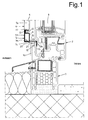
- Fig. 1 shows the lower horizontal Frame profile 5h in cross section, which consists of a rectangular in cross section Base part 9 and two angle profiles 10, 11, of which an optionally arranged at the upper edge of the base part 9 angular profile 11 together with the base part 9 in the direction of the window sash 2 open groove 12 for a piping 13 of the mesh 6 forms.
- the grid fabric 6 is placed loosely over the grid frame 5 and with the piping 13 pressed into the grooves 12 of all frame profiles 5h, 5h ', 5v or rolled up with a roller).
- the other angle profile 10 forms a continuation of the lower base part 9a and extends into the Interior of the window, where there is an angled part 10a forms a stop or support surface 15 with which the lattice frame 5 on an inner counter surface 16 of the lower window frame part 1a rests on the face.
- the window sash 2 comes with the window closed on the side of the angle profile part facing away from the stop or support surface 15 10a to the system.
- the lower base part side 9a forms together with the angle profile 10 an outer surface 14 of the lattice frame 5, on which one from below attached to the outside arcuate arched leaf spring 20, for example riveted is.
- the leaf spring 20 extends below the angle profile 10 approximately up to the stop or support surface 15 Supporting the frame profile 5h on the inner window frame surface 16 acts the leaf spring 20 with a downwardly sloping outer surface 21 one Window frame opening together.
- the outer surface 21 is slanted the inner window frame surface 16 arranged and forms together with this a snap edge 22.
- the frame profile 5h is preferably along its length with two leaf springs 20 equipped.
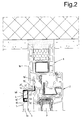
- the upper horizontal frame profile 5h ' is a mirror image to the lower horizontal frame profile 5h, so that the stop or support surface 15 'of its angular profile 10' upwards is directed and on an inner counter surface 16 'of the upper window frame part 1b is present.
- the upper outer surface 14 of the frame profile 5h ' is preferably with two upwardly arched leaf springs 20 'provided with an upper, inclined and a snap edge 22' cooperating outer surface 21 'of the window frame opening.
- the vertical frame profiles 5v of the grid frame 5 on the side with their stop or support surfaces Divide the fixed window frame 1 when inserting the grid frame 5 come to rest and also with a groove for receiving the piping 13 are provided.
- These vertical frame profiles 5v are also open equipped on the outside with two outwardly arched leaf springs, that interact with the side surfaces of the window frame opening.
- the lattice frame 5 which can be used from the inside in the window frame 1 is shown in its outer circumference defined by the outer surfaces 14 is somewhat smaller than the window frame opening, the curvature of the leaf spring 20, 20 'to the outside ensures that the lattice frame 5 in the window frame opening sits tight and cannot fall inside.
- the leaf spring 20, 20 ' run in the direction in which the insertion or removal of the lattice frame 5. When inserting or removing the Lattice frame 5, this resilient leaf spring 20, 20 ' compressed over the snap edges 22, 22 'and in or out Intervention with the window opening brought.
- a fixed window frame 1 insect screen 4A used essentially corresponds the embodiment described above (are the same parts therefore designated with the same reference numbers).
- leaf springs 20A, 20A 'on the front 9b of the frame profile base parts 9 attached, and its curved part extends over the entire outer surface 14 of the respective frame profile. This creates a good spring effect even with less deep angle profiles 10A, i.e. at closer to the window arranged insect screens 4A, reached.
- the leaf springs 20, 20 'and 20A act, 20A 'in cooperation with the snap edges 22, 22' as elastic flexible snap elements for detachable connection of the lattice frame 5 or 5A with the window opening.
- this metal leaf spring could also other snap or locking elements, for example Plastic to be attached to the lattice frame.
- the Snap elements or leaf spring 20, 20 'or 20A, 20A' each of the two assigned to opposite sides of the lattice frame 5 or 5A.
- the snap elements equip, and support the other in the window frame opening.
- FIG. 5 Another embodiment of an insect screen 4B for a window provided with two window sashes 2a, 2b is shown in FIG. 5.
- the 4B insect screen is only in front of the first opening window sash 2a arranged.
- vertical frame profile of the lattice frame 5B e.g. in the same way designed as the frame profiles of Fig. 1, 2 and 3, 4 and in a kind of snap connection to the fixed window frame the other vertical frame profile 5v "with only one, the groove 12 for the Keder 13 forming angle profile 11 equipped.
- Cross-section rectangular base part 9 lies in this frame profile 5v "with its front side 9b directly on a faceplate 23 of the opening Window sash 2b and seals with a sealing tape 24.
- the base parts 9 of the frame profiles could be used instead of the rectangular cross-section shown a square Have cross-section.
- the inventive design of the insect screens 4, 4A, 4B with snap elements attached to the circumference of the lattice frame simple and inexpensive and enables extremely simple assembly and disassembly, in which no loose fasteners and in particular no tools are needed.
- resilient balls or the like could also be used as snap elements be used. Even the shape, if as snap elements leaf springs are provided, could - other than shown - formed , for example by being approximately straight and with a front rounded or edged snap edge (22) would be provided.
Landscapes
- Engineering & Computer Science (AREA)
- Structural Engineering (AREA)
- Life Sciences & Earth Sciences (AREA)
- Insects & Arthropods (AREA)
- Pest Control & Pesticides (AREA)
- Architecture (AREA)
- Civil Engineering (AREA)
- Specific Sealing Or Ventilating Devices For Doors And Windows (AREA)
- Catching Or Destruction (AREA)
- Wing Frames And Configurations (AREA)
Abstract
Description
- Fig. 1
- einen unteren Bereich eines mit einem Insektenschutzgitter-Rahmen ausgestatteten Fensters im vertikalen Querschnitt;
- Fig. 2
- einen oberen Bereich des Fensters nach Fig. 1 im vertikalen Querschnitt;
- Fig. 3
- eine der Fig. 1 entsprechende Darstellung mit einer weiteren Ausführungsform des Insektenschutzgitters;
- Fig. 4
- eine der Fig. 2 entsprechende Darstellung mit der weiteren Ausführungsform des Insektenschutzgitters; und
- Fig. 5
- einen mittleren Teil eines zweiteiligen Fensters mit einem Insektenschutzgitter im horizontalen Querschnitt.
Claims (12)
- Insektenschutzgitter für ein Fenster oder eine Tür, mit einem Gitterrahmen (5; 5A; 5B), der in einen ortsfesten Fenster- bzw. Türrahmen (1) einsetzbar und an diesem stirnseitig abstützbar ist, wobei Befestigungsmittel zur lösbaren Verbindung des Gitterrahmens (5; 5A; 5B) mit dem Fenster- bzw. Türrahmen (1) vorhanden sind, dadurch gekennzeichnet, dass
die Befestigungsmittel als am Gitterrahmen (5; 5A; 5B) angebrachte und mit dem Fenster- bzw. Türrahmen (1) zusammenwirkende Schnappelemente (20, 20'; 20A, 20A') ausgebildet sind. - Insektenschutzgitter nach Anspruch 1, dadurch gekennzeichnet, dass der Gitterrahmen (5, 5A) zwei und zwei parallele Rahmenprofile (5h, 5h'; 5v, 5v') umfasst, wobei die Schnappelemente (20, 20'; 20A, 20A') jeweils mindestens einem der beiden gegenüberliegenden Rahmenprofile (5h, 5h'; 5v, 5v') zugeordnet sind.
- Insektenschutzgitter nach Anspruch 1 oder 2, dadurch gekennzeichnet, dass die Schnappelemente als am Aussenumfang des Gitterrahmens (5; 5A; 5B) angeordnete, nach aussen gewölbte Blattfedern (20, 20'; 20A, 20A') ausgebildet sind, die in der Richtung verlaufen, in welcher der Gitterrahmen (5) in den Fenster- bzw. Türrahmen (1) eingesetzt wird.
- Insektenschutzgitter nach Anspruch 2 oder 3, dadurch gekennzeichnet, dass ein Rahmenprofil (5h, 5h', 5v) jeweils mit zwei über seine Länge verteilten Schnappelementen (20, 20'; 20A, 20A') ausgestattet ist.
- Insektenschutzgitter nach einem der Ansprüche 2 bis 4, dadurch gekennzeichnet, dass die Rahmenprofile (5h, 5h'; 5v) jeweils einen Rahmenprofil-Grundteil (9) eines rechteckförmigen oder quadratischen Querschnitts aufweisen, dessen eine Seite (9a) in einem Winkelprofil (10) fortgesetzt wird und mit diesem zusammen eine Aussenfläche (14, 14') des Gitterrahmens (5) bildet, an welcher die als Blattfeder (20, 20'; 20A, 20A') ausgebildeten Schnappelemente angeordnet sind, wobei das Winkelprofil (10) mit einem nach aussen abgewinkelten Teil (10a) jeweils eine Abstütz- bzw. Anschlagfläche (15) des Gitterrahmens (5) bildet, mit welcher der Gitterrahmen (5) an einer inneren Fläche (16) des Fenster- bzw. Türrahmens (1) stirnseitig abstützbar ist.
- Insektenschutzgitter nach Anspruch 5, dadurch gekennzeichnet, dass bei stirnseitiger Abstützung der Rahmenprofile (5h, 5h'; 5v) an den inneren Flächen (16) des Fenster- bzw. Türrahmens (1) die am Aussenumfang des Gitterrahmens (5; 5A; 5B) angeordneten Blattfeder (20, 20'; 20A, 20A') mit Aussenflächen (21, 21') einer Fenster- bzw. Türrahmenöffnung zusammenwirken, die schräg zu den inneren Fenster- bzw. Türrahmenflächen (16) verlaufen und mit diesen zusammen eine nach innen gerichtete Schnappkante (22) bilden.
- Insektenschutzgitter nach Anspruch 5 oder 6, dadurch gekennzeichnet, dass die Rahmenprofil-Grundteile (9) der Rahmenprofile (5h, 5h') jeweils mit einem weiteren Winkelprofil (11) versehen sind, welches zusammen mit dem jeweiligen Grundteil (9) eine Nut (12) für die Aufnahme eines Gittergewebe-Keders (13) bildet.
- Insektenschutzgitter nach einem der Ansprüche 5 bis 7, dadurch gekennzeichnet, dass die Blattfeder (20, 20') an der die Aussenfläche (14, 14') des Gitterrahmens (5) bildenden Seite (9a) des jeweiligen Rahmenprofil-Grundteiles (9) befestigt, vorzugsweise angenietet, sind.
- Insektenschutzgitter nach einem der Ansprüche 5 bis 7, dadurch gekennzeichnet, dass die Blattfeder (20A, 20A') an einer zur Aussenfläche (14, 14') des Gitterrahmens (5) rechtwinkligen Frontseite (9b) des jeweiligen Rahmenprofil-Grundteiles (9) befestigt, vorzugsweise angenietet, sind.
- Insektenschutzgitter nach einem der Ansprüche 2 bis 9, dadurch gekennzeichnet, dass die einander gegenüberliegende Rahmenprofile (5h, 5h'; 5v) jeweils spiegelbildlich ausgestaltet sind.
- Insektenschutzgitter nach einem der Ansprüche 2 bis 4, dadurch gekennzeichnet, dass die Schnappelemente an drei der vier Rahmenprofile (5h, 5h', 5v) angebracht sind, wobei das vierte Rahmenprofil (5v") mit einer Frontseite (9b) an einer Frontfläche (23) eines vertikal verlaufenden, eine Fensterrahmenöffnung in zwei Teile trennenden Fensterrahmenteils (1c) dichtend anliegt.
- Insektenschutzgitter nach Anspruch 11, dadurch gekennzeichnet, dass die Rahmenprofile (5h, 5h', 5v, 5v") jeweils einen Rahmenprofil-Grundteil (9) eines rechteckförmigen oder quadratischen Querschnitts aufweisen und mit einem Winkelprofil (11) versehen sind, welches zusammen mit dem jeweiligen Grundteil (9) eine Nut (12) für die Aufnahme eines Gittergewebe-Keders (13) bildet.
Applications Claiming Priority (2)
| Application Number | Priority Date | Filing Date | Title |
|---|---|---|---|
| CH00256/02A CH695353A5 (de) | 2002-02-15 | 2002-02-15 | Insektenschutzgitter für ein Fenster oder eine Tür. |
| CH2562002 | 2002-02-15 |
Publications (3)
| Publication Number | Publication Date |
|---|---|
| EP1336718A2 true EP1336718A2 (de) | 2003-08-20 |
| EP1336718A3 EP1336718A3 (de) | 2004-03-10 |
| EP1336718B1 EP1336718B1 (de) | 2007-05-09 |
Family
ID=27618072
Family Applications (1)
| Application Number | Title | Priority Date | Filing Date |
|---|---|---|---|
| EP03405076A Expired - Lifetime EP1336718B1 (de) | 2002-02-15 | 2003-02-11 | Insektenschutzgitter für ein Fenster oder eine Tür |
Country Status (4)
| Country | Link |
|---|---|
| EP (1) | EP1336718B1 (de) |
| AT (1) | ATE362032T1 (de) |
| CH (1) | CH695353A5 (de) |
| DE (1) | DE50307209D1 (de) |
Cited By (1)
| Publication number | Priority date | Publication date | Assignee | Title |
|---|---|---|---|---|
| DE202011000289U1 (de) | 2011-02-09 | 2011-04-07 | Ruco Gmbh | Insektenschutzgitter |
Families Citing this family (1)
| Publication number | Priority date | Publication date | Assignee | Title |
|---|---|---|---|---|
| RU193545U1 (ru) * | 2019-06-25 | 2019-11-01 | Вячеслав Михайлович Обатуров | Держатель москитной сетки |
Citations (2)
| Publication number | Priority date | Publication date | Assignee | Title |
|---|---|---|---|---|
| DE19835390A1 (de) * | 1998-03-13 | 1999-09-16 | Neher Systeme Gmbh & Co Kg | Insektenschutzvorrichtung |
| NL1013151C2 (nl) * | 1999-09-28 | 2001-03-29 | Jan Pieter Oskam H O D N Ho Mu | Hor en bouwpakket voor het vervaardigen daarvan. |
-
2002
- 2002-02-15 CH CH00256/02A patent/CH695353A5/de not_active IP Right Cessation
-
2003
- 2003-02-11 DE DE50307209T patent/DE50307209D1/de not_active Expired - Lifetime
- 2003-02-11 EP EP03405076A patent/EP1336718B1/de not_active Expired - Lifetime
- 2003-02-11 AT AT03405076T patent/ATE362032T1/de active
Patent Citations (2)
| Publication number | Priority date | Publication date | Assignee | Title |
|---|---|---|---|---|
| DE19835390A1 (de) * | 1998-03-13 | 1999-09-16 | Neher Systeme Gmbh & Co Kg | Insektenschutzvorrichtung |
| NL1013151C2 (nl) * | 1999-09-28 | 2001-03-29 | Jan Pieter Oskam H O D N Ho Mu | Hor en bouwpakket voor het vervaardigen daarvan. |
Cited By (1)
| Publication number | Priority date | Publication date | Assignee | Title |
|---|---|---|---|---|
| DE202011000289U1 (de) | 2011-02-09 | 2011-04-07 | Ruco Gmbh | Insektenschutzgitter |
Also Published As
| Publication number | Publication date |
|---|---|
| ATE362032T1 (de) | 2007-06-15 |
| CH695353A5 (de) | 2006-04-13 |
| EP1336718A3 (de) | 2004-03-10 |
| EP1336718B1 (de) | 2007-05-09 |
| DE50307209D1 (de) | 2007-06-21 |
Similar Documents
| Publication | Publication Date | Title |
|---|---|---|
| EP3259428B1 (de) | Dichtungsvorrichtung für fenster- und türelemente | |
| DE202006021264U1 (de) | Tür- und Fensterrahmen mit einem hinterschnittenen Eingriffsbereich für eine Getriebeeinheit | |
| EP3135850A1 (de) | Bandseitige fingerschutzvorrichtung | |
| DD159157A5 (de) | Gliederschuerze | |
| DE102011011113B4 (de) | Rahmensystem eines Partikelschutzgitters | |
| EP2055888A2 (de) | Tür mit Dichtung und Türdichtung hierfür | |
| DE19745750C5 (de) | Kämpfer-Verbinder für Fenster- und Türrahmen | |
| DE3626451A1 (de) | Beschlagteil zur klemmbefestigung an profilen | |
| DE2405620A1 (de) | Ecklager, insbesondere fuer drehkippfenster, -tueren o.dgl. | |
| DE202008018499U1 (de) | Türsystem und Türdichtung | |
| DE69903680T2 (de) | Eckverbindung für einen Rahmen | |
| DE19513954C2 (de) | Zusatzrollo | |
| DE19634322C2 (de) | Vitrine | |
| EP1336718A2 (de) | Insektenschutzgitter für ein Fenster oder eine Tür | |
| DE202021103076U1 (de) | Rollladen-Einlauf, und Rollladen-Einlaufanordnung | |
| EP0922828A2 (de) | Fenster mit Vorsatzscheibe | |
| DE19943195A1 (de) | Fenster, Tür o. dgl. sowie Rahmenprofil hierfür | |
| EP1936083A2 (de) | Stützvorrichtung für ein Scharnier einer Schließeinheit | |
| DE69417410T2 (de) | Laden, welcher infolge einer Schwenkung senkrecht verschoben wird | |
| WO2005078226A1 (de) | Tür mit einem drehbar gelagerten türflügel | |
| DE3148261A1 (de) | Fenster | |
| DE19637919C2 (de) | Decken- oder Seitenlauf-Sektionaltor | |
| DE9101597U1 (de) | Scharnier | |
| EP1510646B1 (de) | Rolladen für Schrankmöbel | |
| EP1762691B1 (de) | Abdichtung einer Tür- oder Fensterecke |
Legal Events
| Date | Code | Title | Description |
|---|---|---|---|
| PUAI | Public reference made under article 153(3) epc to a published international application that has entered the european phase |
Free format text: ORIGINAL CODE: 0009012 |
|
| AK | Designated contracting states |
Designated state(s): AT BE BG CH CY CZ DE DK EE ES FI FR GB GR HU IE IT LI LU MC NL PT SE SI SK TR |
|
| AX | Request for extension of the european patent |
Extension state: AL LT LV MK RO |
|
| PUAL | Search report despatched |
Free format text: ORIGINAL CODE: 0009013 |
|
| AK | Designated contracting states |
Kind code of ref document: A3 Designated state(s): AT BE BG CH CY CZ DE DK EE ES FI FR GB GR HU IE IT LI LU MC NL PT SE SI SK TR |
|
| AX | Request for extension of the european patent |
Extension state: AL LT LV MK RO |
|
| 17P | Request for examination filed |
Effective date: 20040902 |
|
| AKX | Designation fees paid |
Designated state(s): AT BE BG CH CY CZ DE DK EE ES FI FR GB GR HU IE IT LI LU MC NL PT SE SI SK TR |
|
| GRAP | Despatch of communication of intention to grant a patent |
Free format text: ORIGINAL CODE: EPIDOSNIGR1 |
|
| GRAS | Grant fee paid |
Free format text: ORIGINAL CODE: EPIDOSNIGR3 |
|
| GRAA | (expected) grant |
Free format text: ORIGINAL CODE: 0009210 |
|
| AK | Designated contracting states |
Kind code of ref document: B1 Designated state(s): AT BE BG CH CY CZ DE DK EE ES FI FR GB GR HU IE IT LI LU MC NL PT SE SI SK TR |
|
| PG25 | Lapsed in a contracting state [announced via postgrant information from national office to epo] |
Ref country code: FI Free format text: LAPSE BECAUSE OF FAILURE TO SUBMIT A TRANSLATION OF THE DESCRIPTION OR TO PAY THE FEE WITHIN THE PRESCRIBED TIME-LIMIT Effective date: 20070509 |
|
| REG | Reference to a national code |
Ref country code: GB Ref legal event code: FG4D Free format text: NOT ENGLISH |
|
| REG | Reference to a national code |
Ref country code: CH Ref legal event code: EP |
|
| REG | Reference to a national code |
Ref country code: IE Ref legal event code: FG4D Free format text: LANGUAGE OF EP DOCUMENT: GERMAN |
|
| REF | Corresponds to: |
Ref document number: 50307209 Country of ref document: DE Date of ref document: 20070621 Kind code of ref document: P |
|
| REG | Reference to a national code |
Ref country code: CH Ref legal event code: NV Representative=s name: LUCHS & PARTNER PATENTANWAELTE |
|
| PG25 | Lapsed in a contracting state [announced via postgrant information from national office to epo] |
Ref country code: SE Free format text: LAPSE BECAUSE OF FAILURE TO SUBMIT A TRANSLATION OF THE DESCRIPTION OR TO PAY THE FEE WITHIN THE PRESCRIBED TIME-LIMIT Effective date: 20070809 |
|
| PG25 | Lapsed in a contracting state [announced via postgrant information from national office to epo] |
Ref country code: ES Free format text: LAPSE BECAUSE OF FAILURE TO SUBMIT A TRANSLATION OF THE DESCRIPTION OR TO PAY THE FEE WITHIN THE PRESCRIBED TIME-LIMIT Effective date: 20070820 |
|
| ET | Fr: translation filed | ||
| NLV1 | Nl: lapsed or annulled due to failure to fulfill the requirements of art. 29p and 29m of the patents act | ||
| GBV | Gb: ep patent (uk) treated as always having been void in accordance with gb section 77(7)/1977 [no translation filed] |
Effective date: 20070509 |
|
| REG | Reference to a national code |
Ref country code: IE Ref legal event code: FD4D |
|
| PG25 | Lapsed in a contracting state [announced via postgrant information from national office to epo] |
Ref country code: SI Free format text: LAPSE BECAUSE OF FAILURE TO SUBMIT A TRANSLATION OF THE DESCRIPTION OR TO PAY THE FEE WITHIN THE PRESCRIBED TIME-LIMIT Effective date: 20070509 Ref country code: PT Free format text: LAPSE BECAUSE OF FAILURE TO SUBMIT A TRANSLATION OF THE DESCRIPTION OR TO PAY THE FEE WITHIN THE PRESCRIBED TIME-LIMIT Effective date: 20071009 Ref country code: DK Free format text: LAPSE BECAUSE OF FAILURE TO SUBMIT A TRANSLATION OF THE DESCRIPTION OR TO PAY THE FEE WITHIN THE PRESCRIBED TIME-LIMIT Effective date: 20070509 Ref country code: CZ Free format text: LAPSE BECAUSE OF FAILURE TO SUBMIT A TRANSLATION OF THE DESCRIPTION OR TO PAY THE FEE WITHIN THE PRESCRIBED TIME-LIMIT Effective date: 20070509 Ref country code: IE Free format text: LAPSE BECAUSE OF FAILURE TO SUBMIT A TRANSLATION OF THE DESCRIPTION OR TO PAY THE FEE WITHIN THE PRESCRIBED TIME-LIMIT Effective date: 20070509 Ref country code: BG Free format text: LAPSE BECAUSE OF FAILURE TO SUBMIT A TRANSLATION OF THE DESCRIPTION OR TO PAY THE FEE WITHIN THE PRESCRIBED TIME-LIMIT Effective date: 20070809 Ref country code: NL Free format text: LAPSE BECAUSE OF FAILURE TO SUBMIT A TRANSLATION OF THE DESCRIPTION OR TO PAY THE FEE WITHIN THE PRESCRIBED TIME-LIMIT Effective date: 20070509 |
|
| PG25 | Lapsed in a contracting state [announced via postgrant information from national office to epo] |
Ref country code: SK Free format text: LAPSE BECAUSE OF FAILURE TO SUBMIT A TRANSLATION OF THE DESCRIPTION OR TO PAY THE FEE WITHIN THE PRESCRIBED TIME-LIMIT Effective date: 20070509 |
|
| PLBE | No opposition filed within time limit |
Free format text: ORIGINAL CODE: 0009261 |
|
| STAA | Information on the status of an ep patent application or granted ep patent |
Free format text: STATUS: NO OPPOSITION FILED WITHIN TIME LIMIT |
|
| 26N | No opposition filed |
Effective date: 20080212 |
|
| PG25 | Lapsed in a contracting state [announced via postgrant information from national office to epo] |
Ref country code: GB Free format text: LAPSE BECAUSE OF FAILURE TO SUBMIT A TRANSLATION OF THE DESCRIPTION OR TO PAY THE FEE WITHIN THE PRESCRIBED TIME-LIMIT Effective date: 20070509 Ref country code: GR Free format text: LAPSE BECAUSE OF FAILURE TO SUBMIT A TRANSLATION OF THE DESCRIPTION OR TO PAY THE FEE WITHIN THE PRESCRIBED TIME-LIMIT Effective date: 20070810 |
|
| BERE | Be: lapsed |
Owner name: ROLLFIX SYSTEME A.G. Effective date: 20080228 |
|
| PG25 | Lapsed in a contracting state [announced via postgrant information from national office to epo] |
Ref country code: MC Free format text: LAPSE BECAUSE OF NON-PAYMENT OF DUE FEES Effective date: 20080228 |
|
| PG25 | Lapsed in a contracting state [announced via postgrant information from national office to epo] |
Ref country code: EE Free format text: LAPSE BECAUSE OF FAILURE TO SUBMIT A TRANSLATION OF THE DESCRIPTION OR TO PAY THE FEE WITHIN THE PRESCRIBED TIME-LIMIT Effective date: 20070509 |
|
| PG25 | Lapsed in a contracting state [announced via postgrant information from national office to epo] |
Ref country code: BE Free format text: LAPSE BECAUSE OF NON-PAYMENT OF DUE FEES Effective date: 20080228 |
|
| PG25 | Lapsed in a contracting state [announced via postgrant information from national office to epo] |
Ref country code: CY Free format text: LAPSE BECAUSE OF FAILURE TO SUBMIT A TRANSLATION OF THE DESCRIPTION OR TO PAY THE FEE WITHIN THE PRESCRIBED TIME-LIMIT Effective date: 20070509 |
|
| PG25 | Lapsed in a contracting state [announced via postgrant information from national office to epo] |
Ref country code: HU Free format text: LAPSE BECAUSE OF FAILURE TO SUBMIT A TRANSLATION OF THE DESCRIPTION OR TO PAY THE FEE WITHIN THE PRESCRIBED TIME-LIMIT Effective date: 20071110 Ref country code: LU Free format text: LAPSE BECAUSE OF NON-PAYMENT OF DUE FEES Effective date: 20080211 |
|
| PG25 | Lapsed in a contracting state [announced via postgrant information from national office to epo] |
Ref country code: TR Free format text: LAPSE BECAUSE OF FAILURE TO SUBMIT A TRANSLATION OF THE DESCRIPTION OR TO PAY THE FEE WITHIN THE PRESCRIBED TIME-LIMIT Effective date: 20070509 |
|
| REG | Reference to a national code |
Ref country code: FR Ref legal event code: PLFP Year of fee payment: 14 |
|
| REG | Reference to a national code |
Ref country code: FR Ref legal event code: PLFP Year of fee payment: 15 |
|
| REG | Reference to a national code |
Ref country code: FR Ref legal event code: PLFP Year of fee payment: 16 |
|
| PGFP | Annual fee paid to national office [announced via postgrant information from national office to epo] |
Ref country code: DE Payment date: 20220224 Year of fee payment: 20 Ref country code: CH Payment date: 20220224 Year of fee payment: 20 Ref country code: AT Payment date: 20220215 Year of fee payment: 20 |
|
| PGFP | Annual fee paid to national office [announced via postgrant information from national office to epo] |
Ref country code: IT Payment date: 20220218 Year of fee payment: 20 Ref country code: FR Payment date: 20220216 Year of fee payment: 20 |
|
| REG | Reference to a national code |
Ref country code: DE Ref legal event code: R081 Ref document number: 50307209 Country of ref document: DE Owner name: VIPRINS AG, CH Free format text: FORMER OWNER: ROLLFIX SYSTEME AG, STEINHAUSEN, CH |
|
| REG | Reference to a national code |
Ref country code: AT Ref legal event code: PC Ref document number: 362032 Country of ref document: AT Kind code of ref document: T Owner name: VIPRINS AG, CH Effective date: 20220613 |
|
| REG | Reference to a national code |
Ref country code: DE Ref legal event code: R071 Ref document number: 50307209 Country of ref document: DE |
|
| REG | Reference to a national code |
Ref country code: CH Ref legal event code: PL |
|
| REG | Reference to a national code |
Ref country code: AT Ref legal event code: MK07 Ref document number: 362032 Country of ref document: AT Kind code of ref document: T Effective date: 20230211 |