EP1335800B1 - Vorrichtung zur stufenlosen unwuchtverstellung bei lenkbaren vibrationsplatten - Google Patents
Vorrichtung zur stufenlosen unwuchtverstellung bei lenkbaren vibrationsplatten Download PDFInfo
- Publication number
- EP1335800B1 EP1335800B1 EP01997363A EP01997363A EP1335800B1 EP 1335800 B1 EP1335800 B1 EP 1335800B1 EP 01997363 A EP01997363 A EP 01997363A EP 01997363 A EP01997363 A EP 01997363A EP 1335800 B1 EP1335800 B1 EP 1335800B1
- Authority
- EP
- European Patent Office
- Prior art keywords
- fluid
- piston
- delivery pump
- fluid chambers
- storage device
- Prior art date
- Legal status (The legal status is an assumption and is not a legal conclusion. Google has not performed a legal analysis and makes no representation as to the accuracy of the status listed.)
- Expired - Lifetime
Links
- 239000012530 fluid Substances 0.000 claims description 25
- 230000009977 dual effect Effects 0.000 claims 2
- 238000006073 displacement reaction Methods 0.000 claims 1
- 239000007788 liquid Substances 0.000 description 10
- 230000000903 blocking effect Effects 0.000 description 3
- 238000005056 compaction Methods 0.000 description 1
- 230000035939 shock Effects 0.000 description 1
- 238000004904 shortening Methods 0.000 description 1
- 239000002689 soil Substances 0.000 description 1
Images
Classifications
-
- E—FIXED CONSTRUCTIONS
- E02—HYDRAULIC ENGINEERING; FOUNDATIONS; SOIL SHIFTING
- E02D—FOUNDATIONS; EXCAVATIONS; EMBANKMENTS; UNDERGROUND OR UNDERWATER STRUCTURES
- E02D3/00—Improving or preserving soil or rock, e.g. preserving permafrost soil
- E02D3/02—Improving by compacting
- E02D3/046—Improving by compacting by tamping or vibrating, e.g. with auxiliary watering of the soil
- E02D3/074—Vibrating apparatus operating with systems involving rotary unbalanced masses
-
- Y—GENERAL TAGGING OF NEW TECHNOLOGICAL DEVELOPMENTS; GENERAL TAGGING OF CROSS-SECTIONAL TECHNOLOGIES SPANNING OVER SEVERAL SECTIONS OF THE IPC; TECHNICAL SUBJECTS COVERED BY FORMER USPC CROSS-REFERENCE ART COLLECTIONS [XRACs] AND DIGESTS
- Y10—TECHNICAL SUBJECTS COVERED BY FORMER USPC
- Y10T—TECHNICAL SUBJECTS COVERED BY FORMER US CLASSIFICATION
- Y10T74/00—Machine element or mechanism
- Y10T74/18—Mechanical movements
- Y10T74/18544—Rotary to gyratory
- Y10T74/18552—Unbalanced weight
Definitions
- the invention relates according to the preamble of claim 1, a device for stepless unbalance adjustment with steerable vibration plates with a trained as a piston of a hydraulic cylinder, with the associated Imbalance in operatively connected actuator, a memory for hydraulic fluid and a pump for the hydraulic fluid comprehensive pressure source.
- EP-A-0 070 345 is an unbalance vibrator with an adjustable Flyweight known.
- the Unwuchtrüttler has two opposite to each other rotatable unbalanced shafts, one of which is a fixed flyweight carries and the other a directed transversely to the imbalance cylinder. In the cylinder acting as a flyweight piston is guided.
- a pressure medium given and the piston thereby pressed in each case into an end position become.
- the imbalance shaker can be used on a vibrating plate to change the direction of travel in forward and reverse direction.
- each adjustable imbalance is a double acting hydraulic cylinder associated with two fluid chambers, one of which for adjustment a piston either one with the pump and at the same time another is directly connectable to the memory while fixing the Piston in position both fluid chambers opposite at the same time Memory and pump are lockable.
- each double-acting cylinder is assigned a 4/3-way valve, that with a pressure fluid source, a liquid storage, and each of the two fluid chambers of the cylinder is connected.
- each liquid chamber connected to the 4/3-way valve via a throttle check valve.
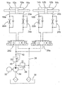
- the example shows two double-acting hydraulic cylinders 10a and 10b, the each serve as a servomotor to a suitable mechanical connection the position of an imbalance of a vibrating plate carried by a shaft optionally and continuously adjust between two end positions to be able to.
- each of the hydraulic cylinders 10a and 10b there is a piston 12a and 12b linearly movable, on both sides of each liquid chambers 14a and 16a and 14b and 16b, respectively.
- Each of the fluid chambers 14a to 16b has a line connection 18a, 20a or 18b, 20b, via a throttle check valve 22a, 24a and 22b, 24b to each one of each of the cylinders 10a and 10b associated 4/3-way valve 26a and 26b leads.
- Each of these 4/3-way valves 26a and 26b has four ports and three Positions. Shown is the blocking position in which the line connections 18a to 20b are interrupted.
- valve bodies 28a and 28b When the valve bodies 28a and 28b are displaced to the right the line ports 18a and 18b pressurized fluid, the from a memory 30 by a motor 32 driven by a pump 34 is promoted.
- the delivery side of the pump 34 is via a pressure relief valve 36 connected to a leading to the memory 30 return 38, and via a pressure control valve 40 and a delivery line 42 with the Valves 26a and 26b.
- the left fluid chambers 14a and 14b become more pressurized Hydraulic fluid is applied, thereby the pistons 12 a and 12b shifts to the right, whereby in the liquid chambers 16a and 16b liquid is displaced.
- the entire repressed Liquid must pass through the throttle branches of the valves 24a and 24b. which creates a resistance which causes the piston movement in the cylinders 10a and 10b decelerates.
- By dimensioning the choke branches and the set on the valve 40 delivery pressure can be the speed of the Movement of the pistons 12a and 12 influence.
- the 4/3-way valve 26a and 26b is transferred to the blocking position shown, with another fluid movement between the 4/3-way valves 26a, 26b and the cylinders 10a and 10b is prevented. As a result, the pistons 12a and 12b are blocked in the position they are closing the valves 26a and 26b have taken.
- valve body of the 4/3-way valves 26a and 26b can be completely independent be adjusted from each other, so that the respective setting of the piston 12a and 12b is completely independent of each other.
Landscapes
- Engineering & Computer Science (AREA)
- Structural Engineering (AREA)
- Life Sciences & Earth Sciences (AREA)
- Paleontology (AREA)
- Soil Sciences (AREA)
- Environmental & Geological Engineering (AREA)
- General Life Sciences & Earth Sciences (AREA)
- Mining & Mineral Resources (AREA)
- Agronomy & Crop Science (AREA)
- Civil Engineering (AREA)
- General Engineering & Computer Science (AREA)
- Road Paving Machines (AREA)
- Reciprocating Pumps (AREA)
- Investigation Of Foundation Soil And Reinforcement Of Foundation Soil By Compacting Or Drainage (AREA)
- Apparatuses For Generation Of Mechanical Vibrations (AREA)
- Vibration Prevention Devices (AREA)
Description
Claims (5)
- Vorrichtung zur stufenlosen Unwuchtverstellung bei lenkbaren Vibrationsplatten, mitwobeizwei verstellbaren Unwuchten, die auf einer gemeinsamen Welle angeordnet sind,einem Speicher (30) für Hydraulikflüssigkeit, und miteiner eine Förderpumpe (34) für die Hydraulikflüssigkeit umfassenden Druckquelle,jeder der verstellbaren Unwuchten ein doppeltwirkender Hydraulikzylinder (10a; 10b) mit zwei Flüssigkeitskammern (14a, 16a; 14b, 16b) und einem die Flüssigkeitskammern (14a, 16a; 14b, 16b) trennenden Kolben (12a; 12b) zugeordnet ist,der Kolben (12a; 12b) als Stellglied mit einer ihm zugeordneten Unwucht in Wirkverbindung steht, und wobeizur Verstellung des Kolbens (12a; 12b) wahlweise die eine der Flüssigkeitskammern (14a, 16a; 14b, 16b) mit der Förderpumpe und zugleich die andere direkt mit dem Speicher (30) verbindbar ist, während zur Fixierung des Kolbens (12a; 12b) in seiner Position beide Flüssigkeitskammern (14a, 16a; 14b, 16b) zugleich gegenüber dem Speicher (30) und der Förderpumpe (34) abschließbar sind.
- Vorrichtung nach Anspruch 1, dadurch gekennzeichnet, daß jedem doppeltwirkenden Zylinder (10a; 10b) ein 4/3-Wegeventil zugeordnet ist, das mit der Förderpumpe (34), dem Flüssigkeitsspeicher (30) und jeder der beiden Flüssigkeitskammern (14a, 16a; 14b, 16b) des Zylinders verbunden ist.
- Vorrichtung nach Anspruch 2, dadurch gekennzeichnet, daß jede Flüssigkeitskammer (14a, 16a; 14b, 16b) mit dem 4/3-Wegeventil (26a; 26b) über ein Drosselrückschlagventil (22a, 24a; 22b, 24b) verbunden ist.
- Vorrichtung nach Anspruch 3, dadurch gekennzeichnet, daß das Drosselrückschlagventil (22a, 24a; 22b, 24b) in einer ersten Passage eine Fluiddrossel und in einer zu der ersten Passage parallel geschalteten zweiten Passage ein Rückschlagventil aufweist.
- Vorrichtung nach einem der Ansprüche 1 bis 4, dadurch gekennzeichnet, daß sie unter Einbeziehung einer Wegmeßeinrichtung einen geschlossenen Regelkreis bildet.
Applications Claiming Priority (3)
| Application Number | Priority Date | Filing Date | Title |
|---|---|---|---|
| DE20019823U DE20019823U1 (de) | 2000-11-22 | 2000-11-22 | Vorrichtung zur stufenlosen Unwuchtverstellung bei lenkbaren Vibrationsplatten |
| DE20019823U | 2000-11-22 | ||
| PCT/EP2001/013557 WO2002042010A1 (de) | 2000-11-22 | 2001-11-21 | Vorrichtung zur stufenlosen unwuchtverstellung bei lenkbaren vibrationsplatten |
Publications (2)
| Publication Number | Publication Date |
|---|---|
| EP1335800A1 EP1335800A1 (de) | 2003-08-20 |
| EP1335800B1 true EP1335800B1 (de) | 2005-06-08 |
Family
ID=7949144
Family Applications (1)
| Application Number | Title | Priority Date | Filing Date |
|---|---|---|---|
| EP01997363A Expired - Lifetime EP1335800B1 (de) | 2000-11-22 | 2001-11-21 | Vorrichtung zur stufenlosen unwuchtverstellung bei lenkbaren vibrationsplatten |
Country Status (5)
| Country | Link |
|---|---|
| US (1) | US7017679B2 (de) |
| EP (1) | EP1335800B1 (de) |
| JP (1) | JP3851270B2 (de) |
| DE (2) | DE20019823U1 (de) |
| WO (1) | WO2002042010A1 (de) |
Families Citing this family (8)
| Publication number | Priority date | Publication date | Assignee | Title |
|---|---|---|---|---|
| ES2233129B1 (es) * | 2002-07-04 | 2006-07-16 | Uma Hermanos Alquezar, S.A. | Sistema vibrador por masa rotativa excentrica. |
| EP1568420B1 (de) | 2004-02-29 | 2018-08-15 | BOMAG GmbH | Steuerung und Steuerungsverfahren für eine Vibrationsmaschine |
| DE102004015589A1 (de) * | 2004-02-29 | 2005-09-15 | Bomag Gmbh | Steuerung und Steuerungsverfahren für eine Vibrationsmaschine |
| DE102005030860A1 (de) * | 2005-07-01 | 2007-01-25 | Wacker Construction Equipment Ag | Vibrationsplattensystem |
| FR2911658B1 (fr) * | 2007-01-22 | 2009-04-24 | Poclain Hydraulics Ind Soc Par | Dispositif de transmission hydrostatique d'un engin. |
| EP2558649B1 (de) * | 2010-04-16 | 2014-11-19 | Ammann Schweiz AG | Anordnung zur bereitstellung einer pulsierenden druckkraft |
| CN113863097A (zh) * | 2021-09-29 | 2021-12-31 | 徐工集团工程机械股份有限公司道路机械分公司 | 一种无级调幅振动轮及压路机 |
| CN119777731B (zh) * | 2025-03-10 | 2025-07-22 | 胜利油田万和石油工程技术有限责任公司 | 一种基于疲劳预测的井下水力振动器 |
Family Cites Families (13)
| Publication number | Priority date | Publication date | Assignee | Title |
|---|---|---|---|---|
| FR1566358A (de) * | 1968-02-09 | 1969-05-09 | ||
| US3990522A (en) * | 1975-06-24 | 1976-11-09 | Mining Equipment Division | Rotary percussion drill |
| US4105356A (en) * | 1977-05-19 | 1978-08-08 | Koehring Corporation | Vibratory roller |
| DE2928870A1 (de) * | 1979-07-17 | 1981-02-12 | Koehring Gmbh Bomag Division | Massenkompensiertes stampf- und/oder schlagsystem |
| IT1150232B (it) * | 1981-03-12 | 1986-12-10 | Linde Ag | Dispositivo di comando per un veicolo sterzato con velocita' differenziale |
| EP0070345A1 (de) * | 1981-07-18 | 1983-01-26 | Losenhausen Maschinenbau AG& Co Kommanditgesellschaft | Unwuchtrüttler mit einem verstellbaren Fliehgewicht |
| US4694649A (en) * | 1983-02-04 | 1987-09-22 | Howeth David F | Pressure limiting acceleration control system and valve for hydraulic motors |
| FR2592903B1 (fr) * | 1986-01-15 | 1988-05-06 | Albaret Ind Sa | Machine de travaux de terrassement avec synchronisation entre le deplacement de la machine et la mise en mouvement d'une partie mobile de celle-ci. |
| SE453000B (sv) * | 1986-06-27 | 1988-01-04 | Dynapac Ab | Vibrationsplatta |
| DE3709112C1 (de) * | 1986-08-27 | 1988-01-28 | Knauer Maschf Gmbh | Ruettelvorrichtung fuer eine Betonsteinformmaschine |
| US4779418A (en) * | 1987-02-17 | 1988-10-25 | M-B-W Inc. | Remote control system for a soil compactor |
| US4759659A (en) * | 1987-07-01 | 1988-07-26 | Fernand Copie | Variable vibrator system |
| NL1008965C2 (nl) * | 1998-04-22 | 1999-10-25 | Int Construction Equipment B V | Werkwijze en inrichting voor het trillend aandrijven van een voorwerp. |
-
2000
- 2000-11-22 DE DE20019823U patent/DE20019823U1/de not_active Expired - Lifetime
-
2001
- 2001-11-21 EP EP01997363A patent/EP1335800B1/de not_active Expired - Lifetime
- 2001-11-21 JP JP2002544179A patent/JP3851270B2/ja not_active Expired - Fee Related
- 2001-11-21 WO PCT/EP2001/013557 patent/WO2002042010A1/de not_active Ceased
- 2001-11-21 US US10/416,874 patent/US7017679B2/en not_active Expired - Fee Related
- 2001-11-21 DE DE50106474T patent/DE50106474D1/de not_active Expired - Lifetime
Also Published As
| Publication number | Publication date |
|---|---|
| DE50106474D1 (de) | 2005-07-14 |
| US7017679B2 (en) | 2006-03-28 |
| DE20019823U1 (de) | 2001-02-08 |
| JP3851270B2 (ja) | 2006-11-29 |
| WO2002042010A1 (de) | 2002-05-30 |
| EP1335800A1 (de) | 2003-08-20 |
| US20040035104A1 (en) | 2004-02-26 |
| JP2004514078A (ja) | 2004-05-13 |
Similar Documents
| Publication | Publication Date | Title |
|---|---|---|
| DE2851773C2 (de) | Hydraulische Hilfskraftlenkeinrichtung für Kraftfahrzeuge | |
| EP0367949B1 (de) | Federungssystem für Fahrzeuge | |
| DE3200944C2 (de) | ||
| EP0759109A1 (de) | Hydraulische anlage für ein mobiles arbeitsgerät, insbesondere für einen radlader | |
| EP1335800A1 (de) | Vorrichtung zur stufenlosen unwuchtverstellung bei lenkbaren vibrationsplatten | |
| DE102009021833A1 (de) | Hydraulischer Antrieb und Drehschieberventil für einen hydraulischen Antrieb | |
| DE2242022B2 (de) | Druckmittelfolgesteuerung für Servolenkungen o.dgl | |
| DE19822439A1 (de) | Vorrichtung zur Durchführung von Betätigungen in einer Druckmaschine | |
| EP0268078A1 (de) | Summen-Leistungsregelvorrichtung für wenigstens zwei hydrostatische Getriebe | |
| DE2356795A1 (de) | Steuereinrichtung fuer eine verstellbare pumpe | |
| DE102018203367A1 (de) | Hydrostatischer Linearantrieb | |
| DE3704312A1 (de) | Elektrohydraulische steueranordnung | |
| DE2218472A1 (de) | Hydrostatisches getriebe | |
| DE10344071B4 (de) | Hydrostatische Verstelleinheit mit Schrägscheibe und einem Servosystem mit einer Federanordnung | |
| DE19757157C2 (de) | Hydraulischer Linearantrieb | |
| DE2944471C2 (de) | Pneumatischer Schwenk- und/oder Drehantrieb | |
| DE102021200285A1 (de) | Verdichtungsfahrzeug, bei welchem ein Fahrantrieb und eine Vibrationseinheit von einer gemeinsamen Versorgungstelle her mit Druckfluid versorgt werden | |
| DE3872889T2 (de) | Pfahlramme. | |
| DE1776206C3 (de) | Bei Druckmittelausfall wirksam werdende Steuereinrichtung für eine hydraulische Servokraftverstärkungseinrichtung | |
| DE2262575C3 (de) | Hydraulische Druckmittelsteueranlage zur Wegesteuerung eines doppeltwirkenden Servomotors | |
| DE1936156C (de) | Durch eine Druckflüssigkeit betriebner Vibrationsantrieb mit einem doppelt wirkenden Schubkolbentrieb | |
| DE19905626A1 (de) | Stellzylinder sowie Verfahren zum Einstellen eines Stellzylinders | |
| DE2223995B2 (de) | Proportionalsteuerung für einen Hydraulikzylinder | |
| DE2947042C2 (de) | Hydraulische Presse | |
| DE2910434A1 (de) | Einrichtung fuer hydraulisch betriebene hubmaschinen, vorschubgeraete u.dgl. |
Legal Events
| Date | Code | Title | Description |
|---|---|---|---|
| PUAI | Public reference made under article 153(3) epc to a published international application that has entered the european phase |
Free format text: ORIGINAL CODE: 0009012 |
|
| 17P | Request for examination filed |
Effective date: 20030513 |
|
| AK | Designated contracting states |
Designated state(s): AT BE CH CY DE DK ES FI FR GB GR IE IT LI LU MC NL PT SE TR |
|
| RBV | Designated contracting states (corrected) |
Designated state(s): CH DE GB LI SE |
|
| GRAP | Despatch of communication of intention to grant a patent |
Free format text: ORIGINAL CODE: EPIDOSNIGR1 |
|
| GRAS | Grant fee paid |
Free format text: ORIGINAL CODE: EPIDOSNIGR3 |
|
| GRAA | (expected) grant |
Free format text: ORIGINAL CODE: 0009210 |
|
| AK | Designated contracting states |
Kind code of ref document: B1 Designated state(s): CH DE GB LI SE |
|
| REG | Reference to a national code |
Ref country code: GB Ref legal event code: FG4D Free format text: NOT ENGLISH |
|
| REG | Reference to a national code |
Ref country code: CH Ref legal event code: NV Representative=s name: E. BLUM & CO. PATENTANWAELTE Ref country code: CH Ref legal event code: EP |
|
| REF | Corresponds to: |
Ref document number: 50106474 Country of ref document: DE Date of ref document: 20050714 Kind code of ref document: P |
|
| GBT | Gb: translation of ep patent filed (gb section 77(6)(a)/1977) |
Effective date: 20050725 |
|
| REG | Reference to a national code |
Ref country code: SE Ref legal event code: TRGR |
|
| PLBE | No opposition filed within time limit |
Free format text: ORIGINAL CODE: 0009261 |
|
| STAA | Information on the status of an ep patent application or granted ep patent |
Free format text: STATUS: NO OPPOSITION FILED WITHIN TIME LIMIT |
|
| 26N | No opposition filed |
Effective date: 20060309 |
|
| REG | Reference to a national code |
Ref country code: CH Ref legal event code: PFA Owner name: WACKER CONSTRUCTION EQUIPMENT AG Free format text: WACKER CONSTRUCTION EQUIPMENT AG#PREUSSENSTRASSE 41#80809 MUENCHEN (DE) -TRANSFER TO- WACKER CONSTRUCTION EQUIPMENT AG#PREUSSENSTRASSE 41#80809 MUENCHEN (DE) |
|
| REG | Reference to a national code |
Ref country code: CH Ref legal event code: PFA Owner name: WACKER NEUSON SE Free format text: WACKER CONSTRUCTION EQUIPMENT AG#PREUSSENSTRASSE 41#80809 MUENCHEN (DE) -TRANSFER TO- WACKER NEUSON SE#PREUSSENSTRASSE 41#80809 MUENCHEN (DE) |
|
| REG | Reference to a national code |
Ref country code: CH Ref legal event code: PUE Owner name: WACKER NEUSON PRODUKTION GMBH & CO. KG Free format text: WACKER NEUSON SE#PREUSSENSTRASSE 41#80809 MUENCHEN (DE) -TRANSFER TO- WACKER NEUSON PRODUKTION GMBH & CO. KG#PREUSSENSTRASSE 41#80809 MUENCHEN (DE) |
|
| REG | Reference to a national code |
Ref country code: DE Ref legal event code: R082 Ref document number: 50106474 Country of ref document: DE Representative=s name: MUELLER - HOFFMANN & PARTNER PATENTANWAELTE, DE |
|
| REG | Reference to a national code |
Ref country code: DE Ref legal event code: R081 Ref document number: 50106474 Country of ref document: DE Owner name: WACKER NEUSON PRODUKTION GMBH & CO. KG, DE Free format text: FORMER OWNER: WACKER NEUSON SE, 80809 MUENCHEN, DE Effective date: 20120326 Ref country code: DE Ref legal event code: R082 Ref document number: 50106474 Country of ref document: DE Representative=s name: MUELLER HOFFMANN & PARTNER PATENTANWAELTE MBB, DE Effective date: 20120326 |
|
| REG | Reference to a national code |
Ref country code: GB Ref legal event code: 732E Free format text: REGISTERED BETWEEN 20120426 AND 20120502 |
|
| PGFP | Annual fee paid to national office [announced via postgrant information from national office to epo] |
Ref country code: CH Payment date: 20151123 Year of fee payment: 15 Ref country code: GB Payment date: 20151123 Year of fee payment: 15 Ref country code: DE Payment date: 20151119 Year of fee payment: 15 |
|
| PGFP | Annual fee paid to national office [announced via postgrant information from national office to epo] |
Ref country code: SE Payment date: 20151123 Year of fee payment: 15 |
|
| REG | Reference to a national code |
Ref country code: DE Ref legal event code: R119 Ref document number: 50106474 Country of ref document: DE |
|
| REG | Reference to a national code |
Ref country code: CH Ref legal event code: PL |
|
| REG | Reference to a national code |
Ref country code: SE Ref legal event code: EUG |
|
| GBPC | Gb: european patent ceased through non-payment of renewal fee |
Effective date: 20161121 |
|
| PG25 | Lapsed in a contracting state [announced via postgrant information from national office to epo] |
Ref country code: LI Free format text: LAPSE BECAUSE OF NON-PAYMENT OF DUE FEES Effective date: 20161130 Ref country code: CH Free format text: LAPSE BECAUSE OF NON-PAYMENT OF DUE FEES Effective date: 20161130 |
|
| PG25 | Lapsed in a contracting state [announced via postgrant information from national office to epo] |
Ref country code: SE Free format text: LAPSE BECAUSE OF NON-PAYMENT OF DUE FEES Effective date: 20161122 |
|
| PG25 | Lapsed in a contracting state [announced via postgrant information from national office to epo] |
Ref country code: DE Free format text: LAPSE BECAUSE OF NON-PAYMENT OF DUE FEES Effective date: 20170601 Ref country code: GB Free format text: LAPSE BECAUSE OF NON-PAYMENT OF DUE FEES Effective date: 20161121 |