EP1335088A2 - Verriegelungs-Vorrichtung zur Verriegelung zweier Strukturteile - Google Patents
Verriegelungs-Vorrichtung zur Verriegelung zweier Strukturteile Download PDFInfo
- Publication number
- EP1335088A2 EP1335088A2 EP03000386A EP03000386A EP1335088A2 EP 1335088 A2 EP1335088 A2 EP 1335088A2 EP 03000386 A EP03000386 A EP 03000386A EP 03000386 A EP03000386 A EP 03000386A EP 1335088 A2 EP1335088 A2 EP 1335088A2
- Authority
- EP
- European Patent Office
- Prior art keywords
- locking
- axis
- locking device
- rocker arm
- hook
- Prior art date
- Legal status (The legal status is an assumption and is not a legal conclusion. Google has not performed a legal analysis and makes no representation as to the accuracy of the status listed.)
- Granted
Links
Images


Classifications
-
- E—FIXED CONSTRUCTIONS
- E05—LOCKS; KEYS; WINDOW OR DOOR FITTINGS; SAFES
- E05B—LOCKS; ACCESSORIES THEREFOR; HANDCUFFS
- E05B47/00—Operating or controlling locks or other fastening devices by electric or magnetic means
- E05B47/02—Movement of the bolt by electromagnetic means; Adaptation of locks, latches, or parts thereof, for movement of the bolt by electromagnetic means
- E05B47/023—Movement of the bolt by electromagnetic means; Adaptation of locks, latches, or parts thereof, for movement of the bolt by electromagnetic means the bolt moving pivotally or rotatively
-
- B—PERFORMING OPERATIONS; TRANSPORTING
- B64—AIRCRAFT; AVIATION; COSMONAUTICS
- B64C—AEROPLANES; HELICOPTERS
- B64C1/00—Fuselages; Constructional features common to fuselages, wings, stabilising surfaces or the like
- B64C1/14—Windows; Doors; Hatch covers or access panels; Surrounding frame structures; Canopies; Windscreens accessories therefor, e.g. pressure sensors, water deflectors, hinges, seals, handles, latches, windscreen wipers
- B64C1/1476—Canopies; Windscreens or similar transparent elements
-
- E—FIXED CONSTRUCTIONS
- E05—LOCKS; KEYS; WINDOW OR DOOR FITTINGS; SAFES
- E05B—LOCKS; ACCESSORIES THEREFOR; HANDCUFFS
- E05B81/00—Power-actuated vehicle locks
- E05B81/02—Power-actuated vehicle locks characterised by the type of actuators used
- E05B81/10—Hydraulic or pneumatic
-
- E—FIXED CONSTRUCTIONS
- E05—LOCKS; KEYS; WINDOW OR DOOR FITTINGS; SAFES
- E05C—BOLTS OR FASTENING DEVICES FOR WINGS, SPECIALLY FOR DOORS OR WINDOWS
- E05C3/00—Fastening devices with bolts moving pivotally or rotatively
- E05C3/02—Fastening devices with bolts moving pivotally or rotatively without latching action
- E05C3/06—Fastening devices with bolts moving pivotally or rotatively without latching action with operating handle or equivalent member moving otherwise than rigidly with the bolt
-
- E—FIXED CONSTRUCTIONS
- E05—LOCKS; KEYS; WINDOW OR DOOR FITTINGS; SAFES
- E05B—LOCKS; ACCESSORIES THEREFOR; HANDCUFFS
- E05B83/00—Vehicle locks specially adapted for particular types of wing or vehicle
- E05B83/16—Locks for luggage compartments, car boot lids or car bonnets
- E05B83/24—Locks for luggage compartments, car boot lids or car bonnets for car bonnets
-
- Y—GENERAL TAGGING OF NEW TECHNOLOGICAL DEVELOPMENTS; GENERAL TAGGING OF CROSS-SECTIONAL TECHNOLOGIES SPANNING OVER SEVERAL SECTIONS OF THE IPC; TECHNICAL SUBJECTS COVERED BY FORMER USPC CROSS-REFERENCE ART COLLECTIONS [XRACs] AND DIGESTS
- Y10—TECHNICAL SUBJECTS COVERED BY FORMER USPC
- Y10T—TECHNICAL SUBJECTS COVERED BY FORMER US CLASSIFICATION
- Y10T292/00—Closure fasteners
- Y10T292/08—Bolts
- Y10T292/0801—Multiple
- Y10T292/0825—Hooked end
-
- Y—GENERAL TAGGING OF NEW TECHNOLOGICAL DEVELOPMENTS; GENERAL TAGGING OF CROSS-SECTIONAL TECHNOLOGIES SPANNING OVER SEVERAL SECTIONS OF THE IPC; TECHNICAL SUBJECTS COVERED BY FORMER USPC CROSS-REFERENCE ART COLLECTIONS [XRACs] AND DIGESTS
- Y10—TECHNICAL SUBJECTS COVERED BY FORMER USPC
- Y10T—TECHNICAL SUBJECTS COVERED BY FORMER US CLASSIFICATION
- Y10T292/00—Closure fasteners
- Y10T292/08—Bolts
- Y10T292/0801—Multiple
- Y10T292/0825—Hooked end
- Y10T292/0826—Operating means
-
- Y—GENERAL TAGGING OF NEW TECHNOLOGICAL DEVELOPMENTS; GENERAL TAGGING OF CROSS-SECTIONAL TECHNOLOGIES SPANNING OVER SEVERAL SECTIONS OF THE IPC; TECHNICAL SUBJECTS COVERED BY FORMER USPC CROSS-REFERENCE ART COLLECTIONS [XRACs] AND DIGESTS
- Y10—TECHNICAL SUBJECTS COVERED BY FORMER USPC
- Y10T—TECHNICAL SUBJECTS COVERED BY FORMER US CLASSIFICATION
- Y10T292/00—Closure fasteners
- Y10T292/08—Bolts
- Y10T292/0801—Multiple
- Y10T292/0825—Hooked end
- Y10T292/0826—Operating means
- Y10T292/0828—Link and lever
-
- Y—GENERAL TAGGING OF NEW TECHNOLOGICAL DEVELOPMENTS; GENERAL TAGGING OF CROSS-SECTIONAL TECHNOLOGIES SPANNING OVER SEVERAL SECTIONS OF THE IPC; TECHNICAL SUBJECTS COVERED BY FORMER USPC CROSS-REFERENCE ART COLLECTIONS [XRACs] AND DIGESTS
- Y10—TECHNICAL SUBJECTS COVERED BY FORMER USPC
- Y10T—TECHNICAL SUBJECTS COVERED BY FORMER US CLASSIFICATION
- Y10T292/00—Closure fasteners
- Y10T292/08—Bolts
- Y10T292/0801—Multiple
- Y10T292/0825—Hooked end
- Y10T292/0826—Operating means
- Y10T292/0831—Lever
Definitions
- the invention relates to a locking device for locking two Structural parts and in particular for locking a cockpit hood of a vehicle and e.g. of an airplane.
- Locking devices are known from the prior art based on the shear pin principle.
- An eye-fork connection is used to lock the cockpit with a locking bolt Eye is moved. Unlocking takes place when the bolt is pulled out this locked position.
- the disadvantage is that frictional forces are overcome need to be used under certain conditions such as large thermal Loads are very high.
- the cockpit hood can be opened Jamming of the locking device can be prevented, especially for the emergency is a serious mistake and must be avoided.
- a locking device for locking two is relative structural parts movable relative to one another are provided by means of a locking hook, that in a joint with an axis for pivoting the locking hook about an axis H by means of an actuator in a reference plane is mounted, at least one locking mechanism with each one cooperating with the actuator for rotation about an axis W.
- Rocker arm is provided, which with a first pivot joint first end of a steering lever is connected, the second end via a second Swivel joint is connected to the locking hook, the axis of rotation W of the rocker arm and the axes of rotation LW1, LW2; LH1, LH2 of the first and of the second swivel joint intersect in the axis H of the locking hook.
- An advantage of the invention is that due to the variety of possible embodiments a multitude of possible uses is given.
- the locking device 1 is in a first structure or Component 3 or housing, which is attached to this, integrated and due the actuation of a control unit (not shown) between a closed one and open position movable. Holds in its closed position the locking device 1 a locking bolt 5 of a bolt fitting 6 engaged, which in the open position of the locking device 1 is released.
- the bolt fitting 6 is part of a second structural part (not shown), which cooperates with the first structural part 3 and by means of the locking device locked against each other and released.
- the first structural part 3 can in particular be part of an aircraft fuselage (not shown) and the second structural part can be part of a cockpit hood. It However, the locking device on the cockpit hood can also be reversed arranged and the bolt fitting 6 or the second structural part in the fuselage be integrated.
- the locking bolt 5 runs in a longitudinal direction 7, which is preferably extends perpendicular to a reference plane 10. 1 to 4 by the location of the reference plane 10 by the location of the rib 9 as part of the Structural part 3 reproduced.
- each rocker arm 13a, 13b acts via a rotary movement the same axis W and by means of a steering lever 15a or 15b on each a locking hook 17a and 17b, respectively, in a common swivel joint 19 mounted with an axis center 20 and an axis or axis direction H. are.
- Both locking hooks are used to lock the locking bolt 5 in a rotational movement with the axis center 20 as a fulcrum on one another too moved.
- Each steering lever has a first end 23a, 23b with the corresponding one Rocker arm 13a or 13b and with a second end 24a, 24b with the corresponding one Locking hooks 17a and 17b articulated.
- the first End 23a, 23b is at a distance A and the second end 24a, 24b in a distance B from the axis W.
- the distances A and B are the same.
- the rocker arm is firmly connected to the drive lever or in the housing or the structural part 3 stored.
- a drive lever 11a or 11b, a steering lever 15a or 15b and a locking hook 17a and 17b each form a locking mechanism 1a and 1b.
- Each rocker arm 13a, 13b is connected to the via a first pivot 21a or 21b Steering lever 15a or 15b articulated, the first pivot 21a or 21b causes an axis of rotation LW1 or LW2.
- a locking mechanism 1a or 1b lie in a reference plane 10, cross in the axis center 20 at an angle 30a or 30b. That angle can be 90 degrees in a starting position.
- the axes W, LW1 and LH1 or LW2 and LH2 of the locking mechanisms 1a and 1b need not be symmetrical to each other when arranged in pairs run if they have the course described above.
- the locking device 1 according to the invention is actuated via at least one drive lever 11.
- FIGS. 1 to 4 is a variant of the object according to the invention with two locking mechanisms 1a and 1b and two drive levers 11a, 11b shown.
- the two locking mechanisms 1a and 1b act with respect to the axis W. together, the drive levers being driven in opposite directions when actuated be so that the steering levers 15a and 15b point symmetrical to the axis center 10 move to the locking hooks 17a and 17b towards each other or move away from each other.
- the directions of actuation also be in the same direction or parallel to each other if with a locking mechanism 1a or 1b a corresponding mechanism for changing the direction of actuation is provided.
- the drive lever is mounted on the swivel joints and can be an additional one be guided in its delivery movement by means of a guide.
- an additional bearing of the drive lever pivot bearing is provided in the structural part 3 be (not shown).
- an actuating element 40 acts e.g. linear in one direction of actuation 41 on the respective drive lever 11a or 11b.
- the actuator 40 can be a transmission rod or a drive element such as e.g. a hydraulic, pneumatic or electric actuating cylinder or actuator his.
- the actuation via a mechanical transmission element such as e.g. a cable pull.
- the linear actuation direction advantageously runs 41 in the direction of the axis of rotation of the swivel joint 19 and the longitudinal direction of the Bolt 5.
- the drive lever 11a or 11b also by means of a rotary drive element e.g. a rotary one Actuator are driven. Such can be done directly with a rocker arm be connected.
- the type and design of the drive elements depend on the respective one Use case and in particular the requirements regarding the available installation space and the drive power to be provided.
- the bearing surface 18a and 18b of the locking hook 17a and 17b, which in the The engagement position thereof partly on the surface of the locking bolt 5 is applied, is preferably spherical. Due to the spherical storage of the Bolt is a bracing of the same and the locking device 1st avoided due to dynamic movements.
- the invention Locking device 1 also include only one locking mechanism 1a.
- a corresponding one instead of a second locking mechanism 1b designed immovable counterpart that is part of the structural part 3.
- This can in particular also have a locking hook which is the counterpart to the movable locking hook 17a for receiving the bolt 5 forms.
- a centering spring F can also be used.
- the steering levers 13a and 13b in one Moved so that the corresponding locking hook 17a or 17b connected ends 24a and 24b are moved in the reference plane 10 and in this way the locking hooks 17a and 17b in the reference plane 10 moved to the open position.
Landscapes
- Engineering & Computer Science (AREA)
- Mechanical Engineering (AREA)
- Physics & Mathematics (AREA)
- Electromagnetism (AREA)
- Aviation & Aerospace Engineering (AREA)
- Lock And Its Accessories (AREA)
- Vehicle Interior And Exterior Ornaments, Soundproofing, And Insulation (AREA)
- Connection Of Plates (AREA)
- Clamps And Clips (AREA)
Abstract
Description
- Fig. 1a
- eine perspektivische Darstellung einer Ausführungsform der erfindungsgemäßen Verriegelungs-Vorrichtung integriert in einem ausschnittsweise dargestellten Strukturteil in ihrer geschlossenen Stellung,
- Fig. 1b
- die Verriegelungs-Vorrichtung nach der Figur 1a in ihrer offenen Stellung,
- Fig. 2
- eine perspektivische Darstellung der Ausführungsform der erfindungsgemäßen Verriegelungs-Vorrichtung nach der Figur 1a oder 1b in seiner offenen Stellung, wobei das Strukturteil, in der die VerriegelungsVorrichtung integriert ist, teilweise aufgebrochen ist,
- Fig. 3
- die Ausführungsform der Verriegelungs-Vorrichtung nach der Fig. 1a oder 1b in der Darstellung der Fig. 2 in ihrer geschlossenen Stellung,
- Fig. 4a
- eine Frontansicht der Ausführungsform der Verriegelungs-Vorrichtung nach der Fig. 1a oder 1b in seiner geschlossenen Stellung,
- Fig. 4b
- die Frontansicht der Ausführungsform der Verriegelungs-Vorrichtung nach der Fig. 4a in seiner offenen Stellung,
- Fig. 4c
- die Verriegelungs-Vorrichtung nach der Fig. 4b von oben gesehen,
- Fig. 5
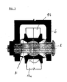
- einen Schnitt durch die in den voranstehend bezeichneten Figuren dargestellte Ausführungsform der erfindungsgemäßen Verriegelungs-Vorrichtung, die in ihrer geschlossenen Stellung einen Verriegelungsbeschlag mit einem Bolzen im Eingriff hält.
Claims (6)
- Verriegelungs-Vorrichtung (1) zur Verriegelung zweier relativ zueinander beweglicher Struktur-Teile mittels eines Verriegelungs-Hakens (17a, 17b), das in einem Gelenk (20) mit einer Achse (20) zur Verschwenkung des Verriegelungs-Hakens um eine Achse (H) mittels eines mit einem Betätigungselement (40a) in einer Bezugsebene (10) gelagert ist,
dadurch gekennzeichnet, dass
zumindest eine Verriegelungs-Mechanik (1a, 1b) mit jeweils einem mit dem Betätigungselement zur Drehung um eine Achse (W) zusammenwirkenden Wipphebel (13a bzw. 13b) vorgesehen ist, der über ein erstes Drehgelenk (23a, 23b; LW) mit dem ersten Ende eines Lenkhebels (15a; 15b) verbunden ist, dessen zweites Ende (24a; 24b) über ein zweites Drehgelenk (22a; 22b) mit dem Verriegelungs-Haken verbunden ist,
wobei die Drehachse (W) des Wipphebels sowie die Drehachsen (LW1, LW2; LH1, LH2) des ersten (21a, 21b) und des zweiten (22a, 22b) Drehgelenks sich in der Achse (H) des Verriegelungs-Hakens kreuzen. - Verriegelungs-Vorrichtung nach dem Anspruch 1, dadurch gekennzeichnet, dass zwei Verriegelungs-Mechaniken (1a, 1b) in Bezug auf die Achse W zusammenwirken, wobei die Antriebshebel bei der Betätigung gegensinnig angetrieben werden, um die Lenkhebel (15a, 15b) zueinander punktsymmetrisch in Bezug auf die Achse (H) der Verriegelungs-Haken zu bewegen, um die Verriegelungshaken aufeinander zu oder voneinander weg zu bewegen.
- Verriegelungs-Vorrichtung nach dem Anspruch 1, dadurch gekennzeichnet, dass die Lagerfläche (18a, 18b) des Verriegelungshakens (17a, 17b), die in der Eingriffsstellung derselben zum Teil an der Oberfläche des Verriegelungsbolzens 5 anliegt, sphärisch gebildet ist.
- Verriegelungs-Vorrichtung nach einem der voranstehenden Ansprüche 1 bis 3, dadurch gekennzeichnet, dass zur Betätigung eines Antriebshebels (11a, 11b) ein Betätigungselement (40) linear auf den jeweiligen Antriebshebel (11a, 11b) wirkt.
- Verriegelungs-Vorrichtung nach dem Anspruch 4, dadurch gekennzeichnet, dass das Betätigungselement (40) ein hydraulischer, pneumatischer oder elektrischer Stellantrieb ist.
- Verriegelungs-Vorrichtung nach dem Anspruch 4, dadurch gekennzeichnet, dass ein rotatorischer Stellantrieb auf den Wipphebel wirkt, um diesen zu betätigen.
Applications Claiming Priority (2)
| Application Number | Priority Date | Filing Date | Title |
|---|---|---|---|
| DE10203523A DE10203523B4 (de) | 2002-01-14 | 2002-01-14 | Verriegelungs-Vorrichtung zur Verriegelung zweier Strukturteile |
| DE10203523 | 2002-01-14 |
Publications (3)
| Publication Number | Publication Date |
|---|---|
| EP1335088A2 true EP1335088A2 (de) | 2003-08-13 |
| EP1335088A3 EP1335088A3 (de) | 2004-12-08 |
| EP1335088B1 EP1335088B1 (de) | 2010-01-06 |
Family
ID=7713369
Family Applications (1)
| Application Number | Title | Priority Date | Filing Date |
|---|---|---|---|
| EP03000386A Expired - Lifetime EP1335088B1 (de) | 2002-01-14 | 2003-01-10 | Verriegelungs-Vorrichtung zur Verriegelung zweier Strukturteile |
Country Status (5)
| Country | Link |
|---|---|
| US (1) | US6729661B2 (de) |
| EP (1) | EP1335088B1 (de) |
| AT (1) | ATE454521T1 (de) |
| CA (1) | CA2415844C (de) |
| DE (2) | DE10203523B4 (de) |
Cited By (4)
| Publication number | Priority date | Publication date | Assignee | Title |
|---|---|---|---|---|
| EP1707718A3 (de) * | 2005-03-21 | 2008-12-03 | Goodrich Actuation Systems Ltd. | Verriegelungsvorrichtung |
| FR2926580A1 (fr) * | 2008-01-22 | 2009-07-24 | Peugeot Citroen Automobiles Sa | Crochet de securite d'une serrure de capot d'un vehicule automobile et procedes de fabrication |
| EP3246497A1 (de) * | 2016-05-17 | 2017-11-22 | Hamilton Sundstrand Corporation | Verriegelungsmechanismus |
| FR3106170A1 (fr) * | 2020-01-10 | 2021-07-16 | Safran Landing Systems | Olive pour crochet de verrouillage |
Families Citing this family (16)
| Publication number | Priority date | Publication date | Assignee | Title |
|---|---|---|---|---|
| US7267377B2 (en) * | 2002-12-11 | 2007-09-11 | Tri/Mark Corporation | Latch assembly for a movable closure element |
| US7448656B1 (en) * | 2007-04-30 | 2008-11-11 | Honeywell International Inc. | Dual action structural latch |
| US8814094B2 (en) * | 2008-04-04 | 2014-08-26 | Tactair Fluid Controls, Inc. | Locking mechanism with bi-modal actuator |
| DE102008028068B4 (de) * | 2008-06-12 | 2015-06-18 | Gantner Electronic Gmbh | Elektromechanische Schließvorrichtung |
| US10295080B2 (en) * | 2012-12-11 | 2019-05-21 | Schneider Electric Buildings, Llc | Fast attachment open end direct mount damper and valve actuator |
| GB2532969A (en) * | 2014-12-01 | 2016-06-08 | Edo Mbm Tech Ltd | Small store suspension and release unit |
| US10077586B2 (en) * | 2016-02-12 | 2018-09-18 | Vac-Tron Equipment, Llc | Door locking device for debris tank |
| GB2553800B (en) | 2016-09-14 | 2018-10-24 | Energwave Nautilus Ltd | Producing compressed air from ocean waves |
| JP6798459B2 (ja) * | 2017-09-20 | 2020-12-09 | トヨタ自動車株式会社 | ステアリングロック装置 |
| JP6863952B2 (ja) * | 2018-11-12 | 2021-04-21 | 豊田鉄工株式会社 | フードロック装置 |
| GB201910909D0 (en) | 2019-07-31 | 2019-09-11 | Camlock Systems Ltd | Latching assembly |
| EP4028618B1 (de) * | 2019-09-12 | 2024-01-03 | Southco, Inc. | Drehverriegelungsanordnung mit mehrfachschlagbolzeneingriffen |
| JP7363445B2 (ja) * | 2019-12-16 | 2023-10-18 | 株式会社アイシン | 車両用ドアロック装置及び車両用ドアロックシステム |
| CN113594786B (zh) * | 2021-08-06 | 2024-04-12 | 北京主导时代科技有限公司 | 一种对接装置 |
| CN114251029B (zh) * | 2021-12-24 | 2022-10-04 | 宁波奥云德电器有限公司 | 一种具有自锁功能的连杆机构 |
| CN117985250B (zh) * | 2024-04-07 | 2024-07-02 | 四川凌空天行科技有限公司 | 一种快速脱伞系统及飞行器 |
Family Cites Families (12)
| Publication number | Priority date | Publication date | Assignee | Title |
|---|---|---|---|---|
| US422739A (en) * | 1890-03-04 | Soil-pipe stopper or closer | ||
| DE713342C (de) * | 1935-12-27 | 1941-11-07 | Aeroplanes Morane Saulnier Soc | Von innen bedienbares, abnehmbares Verdeck fuer den Sitz- oder Fuehrerraum eines Luftfahrzeugs |
| US2506943A (en) * | 1947-07-28 | 1950-05-09 | Tyler Fixture Corp | Latch |
| US2593545A (en) * | 1949-03-15 | 1952-04-22 | Barbe Joseph R De | Combination hinge and latch means for gates or the like |
| US2693099A (en) * | 1951-02-02 | 1954-11-02 | Briggs Mfg Co | Deck lid lock |
| US2924403A (en) * | 1956-06-12 | 1960-02-09 | Gen Dynamics Corp | Actuator device |
| US3413025A (en) * | 1967-05-01 | 1968-11-26 | Bell Aerospace Corp | Sliding closure latch |
| US3666305A (en) * | 1970-12-04 | 1972-05-30 | Ford Motor Co | Door latch assembly |
| GB2239892B (en) * | 1989-11-17 | 1993-06-16 | Abt Hardware Limited | Espagnolette |
| US5171048A (en) * | 1991-03-07 | 1992-12-15 | The Eastern Company | Vehicle door lock assembly |
| US5209530A (en) * | 1992-09-02 | 1993-05-11 | A. L. Hansen Mfg. Co. | Latch |
| DE19629361C1 (de) * | 1996-07-20 | 1997-11-20 | Heraeus Instr Gmbh | Schloß |
-
2002
- 2002-01-14 DE DE10203523A patent/DE10203523B4/de not_active Expired - Fee Related
-
2003
- 2003-01-08 CA CA2415844A patent/CA2415844C/en not_active Expired - Fee Related
- 2003-01-10 AT AT03000386T patent/ATE454521T1/de not_active IP Right Cessation
- 2003-01-10 EP EP03000386A patent/EP1335088B1/de not_active Expired - Lifetime
- 2003-01-10 DE DE50312307T patent/DE50312307D1/de not_active Expired - Lifetime
- 2003-01-14 US US10/341,592 patent/US6729661B2/en not_active Expired - Lifetime
Cited By (5)
| Publication number | Priority date | Publication date | Assignee | Title |
|---|---|---|---|---|
| EP1707718A3 (de) * | 2005-03-21 | 2008-12-03 | Goodrich Actuation Systems Ltd. | Verriegelungsvorrichtung |
| FR2926580A1 (fr) * | 2008-01-22 | 2009-07-24 | Peugeot Citroen Automobiles Sa | Crochet de securite d'une serrure de capot d'un vehicule automobile et procedes de fabrication |
| EP3246497A1 (de) * | 2016-05-17 | 2017-11-22 | Hamilton Sundstrand Corporation | Verriegelungsmechanismus |
| US10597915B2 (en) | 2016-05-17 | 2020-03-24 | Hamilton Sundstrand Corporation | Locking mechanism |
| FR3106170A1 (fr) * | 2020-01-10 | 2021-07-16 | Safran Landing Systems | Olive pour crochet de verrouillage |
Also Published As
| Publication number | Publication date |
|---|---|
| US6729661B2 (en) | 2004-05-04 |
| CA2415844A1 (en) | 2003-07-14 |
| DE10203523A1 (de) | 2003-07-31 |
| EP1335088B1 (de) | 2010-01-06 |
| EP1335088A3 (de) | 2004-12-08 |
| ATE454521T1 (de) | 2010-01-15 |
| DE50312307D1 (de) | 2010-02-25 |
| CA2415844C (en) | 2010-05-04 |
| DE10203523B4 (de) | 2006-12-14 |
| US20030155776A1 (en) | 2003-08-21 |
Similar Documents
| Publication | Publication Date | Title |
|---|---|---|
| EP1335088B1 (de) | Verriegelungs-Vorrichtung zur Verriegelung zweier Strukturteile | |
| DE69300190T2 (de) | Einhakenvorrichtung, mit Befestigung der Fahrwerkeinfahrverriegelung eines Flugzeuges. | |
| DE10218307B4 (de) | Dachkonstruktion für ein Cabriolet | |
| EP2467297B1 (de) | Verstellmechanismus einer verstellvorrichtung zur ankopplung einer verstellklappe an einen hauptflügel und eine solche verstellvorrichtung | |
| EP2362041B1 (de) | Minenschutzverriegelung zur Anordnung an Türen von militärischen Fahrzeugen | |
| DE102018127106B3 (de) | Flugzeugtürverriegelungssystem und Flugzeugtüranordnung | |
| DE102018001021A1 (de) | Entriegelungsvorrichtung für eine Fahrzeugklappe eines Fahrzeugs mit einem Fahrzeugschloss | |
| DE102008008747B4 (de) | Schließsystem | |
| DE102019101278B4 (de) | Kugelgelenk und Haltearm mit solchen Kugelgelenken | |
| DE102020115575A1 (de) | Prothesenhand | |
| DE2206116A1 (de) | Seilzug- bzw. Stangenzug vorrichtung mit zwei Gesperren | |
| DE19916191B4 (de) | Vorrichtung zur Verriegelung einer Haube eines Kraftfahrzeuges | |
| DE102024002097B3 (de) | Klappenvorrichtung für einen Kraftwagen sowie Anordnung | |
| DE102015224949B4 (de) | Kupplungsvorrichtung für eine lösbare Steckerverbindung zwischen einer Schleppantenne und einem Wasserfahrzeug | |
| DE102019207075B3 (de) | Parksperrensystem | |
| EP2859255A1 (de) | Parksperre für ein getriebe eines kraftwagens | |
| DE102004018244B4 (de) | Handschalthebel für ein Fahrzeuggetriebe | |
| DE102017119011A1 (de) | Getriebescharnier | |
| EP2199729A2 (de) | Schwenkluke, insbesondere für militärische Fahrzeuge | |
| DE102015117625A1 (de) | Einrichtung zur Realisierung einer Verschwenkkraftkomponente | |
| DE102016116319B4 (de) | Schiebetürgetriebe mit Übertotpunktverriegelung | |
| EP4467373B1 (de) | Verschlussvorrichtung für ein verdeck eines kraftfahrzeuges mit nocken zur sicherung der übertotpunktlage | |
| EP2708398A2 (de) | Kinematik für eine Klappe | |
| DE102020215389B3 (de) | Hebelgetriebe für einen Radwindabweiser sowie Verfahren zum Betrieb eines Hebelgetriebes mit Überlastschutz | |
| DE102018133301A1 (de) | Schloss für ein Kraftfahrzeug |
Legal Events
| Date | Code | Title | Description |
|---|---|---|---|
| PUAI | Public reference made under article 153(3) epc to a published international application that has entered the european phase |
Free format text: ORIGINAL CODE: 0009012 |
|
| AK | Designated contracting states |
Designated state(s): AT BE BG CH CY CZ DE DK EE ES FI FR GB GR HU IE IT LI LU MC NL PT SE SI SK TR |
|
| AX | Request for extension of the european patent |
Extension state: AL LT LV MK RO |
|
| PUAL | Search report despatched |
Free format text: ORIGINAL CODE: 0009013 |
|
| AK | Designated contracting states |
Kind code of ref document: A3 Designated state(s): AT BE BG CH CY CZ DE DK EE ES FI FR GB GR HU IE IT LI LU MC NL PT SE SI SK TR |
|
| AX | Request for extension of the european patent |
Extension state: AL LT LV MK RO |
|
| RIC1 | Information provided on ipc code assigned before grant |
Ipc: 7E 05C 3/06 B Ipc: 7B 64C 1/14 B Ipc: 7E 05C 3/34 B Ipc: 7B 64D 29/06 B Ipc: 7E 05C 3/02 A |
|
| 17P | Request for examination filed |
Effective date: 20050316 |
|
| AKX | Designation fees paid |
Designated state(s): AT BE BG CH CY CZ DE DK EE ES FI FR GB GR HU IE IT LI LU MC NL PT SE SI SK TR |
|
| GRAP | Despatch of communication of intention to grant a patent |
Free format text: ORIGINAL CODE: EPIDOSNIGR1 |
|
| GRAS | Grant fee paid |
Free format text: ORIGINAL CODE: EPIDOSNIGR3 |
|
| GRAA | (expected) grant |
Free format text: ORIGINAL CODE: 0009210 |
|
| AK | Designated contracting states |
Kind code of ref document: B1 Designated state(s): AT BE BG CH CY CZ DE DK EE ES FI FR GB GR HU IE IT LI LU MC NL PT SE SI SK TR |
|
| REG | Reference to a national code |
Ref country code: GB Ref legal event code: FG4D Free format text: NOT ENGLISH |
|
| REG | Reference to a national code |
Ref country code: CH Ref legal event code: EP |
|
| REG | Reference to a national code |
Ref country code: IE Ref legal event code: FG4D |
|
| REF | Corresponds to: |
Ref document number: 50312307 Country of ref document: DE Date of ref document: 20100225 Kind code of ref document: P |
|
| REG | Reference to a national code |
Ref country code: NL Ref legal event code: VDEP Effective date: 20100106 |
|
| PG25 | Lapsed in a contracting state [announced via postgrant information from national office to epo] |
Ref country code: SI Free format text: LAPSE BECAUSE OF FAILURE TO SUBMIT A TRANSLATION OF THE DESCRIPTION OR TO PAY THE FEE WITHIN THE PRESCRIBED TIME-LIMIT Effective date: 20100106 |
|
| PG25 | Lapsed in a contracting state [announced via postgrant information from national office to epo] |
Ref country code: ES Free format text: LAPSE BECAUSE OF FAILURE TO SUBMIT A TRANSLATION OF THE DESCRIPTION OR TO PAY THE FEE WITHIN THE PRESCRIBED TIME-LIMIT Effective date: 20100417 Ref country code: PT Free format text: LAPSE BECAUSE OF FAILURE TO SUBMIT A TRANSLATION OF THE DESCRIPTION OR TO PAY THE FEE WITHIN THE PRESCRIBED TIME-LIMIT Effective date: 20100506 Ref country code: NL Free format text: LAPSE BECAUSE OF FAILURE TO SUBMIT A TRANSLATION OF THE DESCRIPTION OR TO PAY THE FEE WITHIN THE PRESCRIBED TIME-LIMIT Effective date: 20100106 |
|
| BERE | Be: lapsed |
Owner name: EADS DEUTSCHLAND G.M.B.H. Effective date: 20100131 |
|
| REG | Reference to a national code |
Ref country code: IE Ref legal event code: FD4D |
|
| PG25 | Lapsed in a contracting state [announced via postgrant information from national office to epo] |
Ref country code: MC Free format text: LAPSE BECAUSE OF NON-PAYMENT OF DUE FEES Effective date: 20100131 Ref country code: FI Free format text: LAPSE BECAUSE OF FAILURE TO SUBMIT A TRANSLATION OF THE DESCRIPTION OR TO PAY THE FEE WITHIN THE PRESCRIBED TIME-LIMIT Effective date: 20100106 |
|
| REG | Reference to a national code |
Ref country code: CH Ref legal event code: PL |
|
| PG25 | Lapsed in a contracting state [announced via postgrant information from national office to epo] |
Ref country code: CH Free format text: LAPSE BECAUSE OF NON-PAYMENT OF DUE FEES Effective date: 20100131 Ref country code: CY Free format text: LAPSE BECAUSE OF FAILURE TO SUBMIT A TRANSLATION OF THE DESCRIPTION OR TO PAY THE FEE WITHIN THE PRESCRIBED TIME-LIMIT Effective date: 20100106 Ref country code: SE Free format text: LAPSE BECAUSE OF FAILURE TO SUBMIT A TRANSLATION OF THE DESCRIPTION OR TO PAY THE FEE WITHIN THE PRESCRIBED TIME-LIMIT Effective date: 20100106 Ref country code: LI Free format text: LAPSE BECAUSE OF NON-PAYMENT OF DUE FEES Effective date: 20100131 Ref country code: IE Free format text: LAPSE BECAUSE OF FAILURE TO SUBMIT A TRANSLATION OF THE DESCRIPTION OR TO PAY THE FEE WITHIN THE PRESCRIBED TIME-LIMIT Effective date: 20100106 Ref country code: GR Free format text: LAPSE BECAUSE OF FAILURE TO SUBMIT A TRANSLATION OF THE DESCRIPTION OR TO PAY THE FEE WITHIN THE PRESCRIBED TIME-LIMIT Effective date: 20100407 Ref country code: EE Free format text: LAPSE BECAUSE OF FAILURE TO SUBMIT A TRANSLATION OF THE DESCRIPTION OR TO PAY THE FEE WITHIN THE PRESCRIBED TIME-LIMIT Effective date: 20100106 |
|
| PLBE | No opposition filed within time limit |
Free format text: ORIGINAL CODE: 0009261 |
|
| STAA | Information on the status of an ep patent application or granted ep patent |
Free format text: STATUS: NO OPPOSITION FILED WITHIN TIME LIMIT |
|
| PG25 | Lapsed in a contracting state [announced via postgrant information from national office to epo] |
Ref country code: BG Free format text: LAPSE BECAUSE OF FAILURE TO SUBMIT A TRANSLATION OF THE DESCRIPTION OR TO PAY THE FEE WITHIN THE PRESCRIBED TIME-LIMIT Effective date: 20100406 Ref country code: CZ Free format text: LAPSE BECAUSE OF FAILURE TO SUBMIT A TRANSLATION OF THE DESCRIPTION OR TO PAY THE FEE WITHIN THE PRESCRIBED TIME-LIMIT Effective date: 20100106 Ref country code: SK Free format text: LAPSE BECAUSE OF FAILURE TO SUBMIT A TRANSLATION OF THE DESCRIPTION OR TO PAY THE FEE WITHIN THE PRESCRIBED TIME-LIMIT Effective date: 20100106 |
|
| 26N | No opposition filed |
Effective date: 20101007 |
|
| PG25 | Lapsed in a contracting state [announced via postgrant information from national office to epo] |
Ref country code: DK Free format text: LAPSE BECAUSE OF FAILURE TO SUBMIT A TRANSLATION OF THE DESCRIPTION OR TO PAY THE FEE WITHIN THE PRESCRIBED TIME-LIMIT Effective date: 20100106 |
|
| PG25 | Lapsed in a contracting state [announced via postgrant information from national office to epo] |
Ref country code: BE Free format text: LAPSE BECAUSE OF NON-PAYMENT OF DUE FEES Effective date: 20100131 |
|
| PG25 | Lapsed in a contracting state [announced via postgrant information from national office to epo] |
Ref country code: AT Free format text: LAPSE BECAUSE OF NON-PAYMENT OF DUE FEES Effective date: 20100110 |
|
| PG25 | Lapsed in a contracting state [announced via postgrant information from national office to epo] |
Ref country code: HU Free format text: LAPSE BECAUSE OF FAILURE TO SUBMIT A TRANSLATION OF THE DESCRIPTION OR TO PAY THE FEE WITHIN THE PRESCRIBED TIME-LIMIT Effective date: 20100707 Ref country code: LU Free format text: LAPSE BECAUSE OF NON-PAYMENT OF DUE FEES Effective date: 20100110 |
|
| PG25 | Lapsed in a contracting state [announced via postgrant information from national office to epo] |
Ref country code: TR Free format text: LAPSE BECAUSE OF FAILURE TO SUBMIT A TRANSLATION OF THE DESCRIPTION OR TO PAY THE FEE WITHIN THE PRESCRIBED TIME-LIMIT Effective date: 20100106 |
|
| REG | Reference to a national code |
Ref country code: DE Ref legal event code: R081 Ref document number: 50312307 Country of ref document: DE Owner name: AIRBUS DEFENCE AND SPACE GMBH, DE Free format text: FORMER OWNER: EADS DEUTSCHLAND GMBH, 85521 OTTOBRUNN, DE Effective date: 20140814 |
|
| REG | Reference to a national code |
Ref country code: FR Ref legal event code: PLFP Year of fee payment: 14 |
|
| PGFP | Annual fee paid to national office [announced via postgrant information from national office to epo] |
Ref country code: IT Payment date: 20160127 Year of fee payment: 14 Ref country code: DE Payment date: 20160120 Year of fee payment: 14 |
|
| PGFP | Annual fee paid to national office [announced via postgrant information from national office to epo] |
Ref country code: GB Payment date: 20160120 Year of fee payment: 14 Ref country code: FR Payment date: 20160121 Year of fee payment: 14 |
|
| REG | Reference to a national code |
Ref country code: DE Ref legal event code: R119 Ref document number: 50312307 Country of ref document: DE |
|
| GBPC | Gb: european patent ceased through non-payment of renewal fee |
Effective date: 20170110 |
|
| REG | Reference to a national code |
Ref country code: FR Ref legal event code: ST Effective date: 20170929 |
|
| PG25 | Lapsed in a contracting state [announced via postgrant information from national office to epo] |
Ref country code: FR Free format text: LAPSE BECAUSE OF NON-PAYMENT OF DUE FEES Effective date: 20170131 |
|
| PG25 | Lapsed in a contracting state [announced via postgrant information from national office to epo] |
Ref country code: GB Free format text: LAPSE BECAUSE OF NON-PAYMENT OF DUE FEES Effective date: 20170110 Ref country code: DE Free format text: LAPSE BECAUSE OF NON-PAYMENT OF DUE FEES Effective date: 20170801 |
|
| PG25 | Lapsed in a contracting state [announced via postgrant information from national office to epo] |
Ref country code: IT Free format text: LAPSE BECAUSE OF NON-PAYMENT OF DUE FEES Effective date: 20170110 |