EP1334865B1 - Automatisch Vertikalverkeilungseinrichtung eines Fahrzeugsitzes - Google Patents
Automatisch Vertikalverkeilungseinrichtung eines Fahrzeugsitzes Download PDFInfo
- Publication number
- EP1334865B1 EP1334865B1 EP03356005A EP03356005A EP1334865B1 EP 1334865 B1 EP1334865 B1 EP 1334865B1 EP 03356005 A EP03356005 A EP 03356005A EP 03356005 A EP03356005 A EP 03356005A EP 1334865 B1 EP1334865 B1 EP 1334865B1
- Authority
- EP
- European Patent Office
- Prior art keywords
- wedging
- journal
- slideway
- vertical
- returns
- Prior art date
- Legal status (The legal status is an assumption and is not a legal conclusion. Google has not performed a legal analysis and makes no representation as to the accuracy of the status listed.)
- Expired - Lifetime
Links
- 230000000295 complement effect Effects 0.000 claims description 7
- 239000003190 viscoelastic substance Substances 0.000 claims description 2
- 238000004519 manufacturing process Methods 0.000 description 4
- 238000006073 displacement reaction Methods 0.000 description 3
- 238000000605 extraction Methods 0.000 description 3
- 230000035939 shock Effects 0.000 description 2
- 238000009825 accumulation Methods 0.000 description 1
- 244000245420 ail Species 0.000 description 1
- 238000004873 anchoring Methods 0.000 description 1
- 239000006185 dispersion Substances 0.000 description 1
- 230000000694 effects Effects 0.000 description 1
- 238000009434 installation Methods 0.000 description 1
- 239000000463 material Substances 0.000 description 1
- 229910001092 metal group alloy Inorganic materials 0.000 description 1
- 210000000056 organ Anatomy 0.000 description 1
- 230000001737 promoting effect Effects 0.000 description 1
- 230000001681 protective effect Effects 0.000 description 1
- 230000000452 restraining effect Effects 0.000 description 1
Images


Classifications
-
- B—PERFORMING OPERATIONS; TRANSPORTING
- B60—VEHICLES IN GENERAL
- B60N—SEATS SPECIALLY ADAPTED FOR VEHICLES; VEHICLE PASSENGER ACCOMMODATION NOT OTHERWISE PROVIDED FOR
- B60N2/00—Seats specially adapted for vehicles; Arrangement or mounting of seats in vehicles
- B60N2/005—Arrangement or mounting of seats in vehicles, e.g. dismountable auxiliary seats
- B60N2/015—Attaching seats directly to vehicle chassis
- B60N2/01508—Attaching seats directly to vehicle chassis using quick release attachments
- B60N2/01516—Attaching seats directly to vehicle chassis using quick release attachments with locking mechanisms
- B60N2/01558—Attaching seats directly to vehicle chassis using quick release attachments with locking mechanisms with key and slot
- B60N2/01566—Attaching seats directly to vehicle chassis using quick release attachments with locking mechanisms with key and slot key rotating about a vertical axis
-
- B—PERFORMING OPERATIONS; TRANSPORTING
- B60—VEHICLES IN GENERAL
- B60N—SEATS SPECIALLY ADAPTED FOR VEHICLES; VEHICLE PASSENGER ACCOMMODATION NOT OTHERWISE PROVIDED FOR
- B60N2/00—Seats specially adapted for vehicles; Arrangement or mounting of seats in vehicles
- B60N2/005—Arrangement or mounting of seats in vehicles, e.g. dismountable auxiliary seats
- B60N2/015—Attaching seats directly to vehicle chassis
- B60N2/01508—Attaching seats directly to vehicle chassis using quick release attachments
- B60N2/01516—Attaching seats directly to vehicle chassis using quick release attachments with locking mechanisms
- B60N2/01525—Attaching seats directly to vehicle chassis using quick release attachments with locking mechanisms with locking elements expanding inside or under the vehicle floor or rail
- B60N2/01541—Attaching seats directly to vehicle chassis using quick release attachments with locking mechanisms with locking elements expanding inside or under the vehicle floor or rail using moving hooks
-
- B—PERFORMING OPERATIONS; TRANSPORTING
- B60—VEHICLES IN GENERAL
- B60N—SEATS SPECIALLY ADAPTED FOR VEHICLES; VEHICLE PASSENGER ACCOMMODATION NOT OTHERWISE PROVIDED FOR
- B60N2/00—Seats specially adapted for vehicles; Arrangement or mounting of seats in vehicles
- B60N2/24—Seats specially adapted for vehicles; Arrangement or mounting of seats in vehicles for particular purposes or particular vehicles
- B60N2/42—Seats specially adapted for vehicles; Arrangement or mounting of seats in vehicles for particular purposes or particular vehicles the seat constructed to protect the occupant from the effect of abnormal g-forces, e.g. crash or safety seats
Definitions
- the invention relates to a vertical and automatic wedging device in C-rails of a removable vehicle seat. It relates more particularly to the removable seats comprising, on the one hand, positioning means in longitudinal rails fixed to the floor of the vehicle, on the other hand, retaining hooks, adapted to cooperate with the internal returns of the slide when the seat is subjected to shock energy and, in addition, means for adjusting their longitudinal position, with locking in the chosen position.
- Document EP 1 176 047 discloses a guiding and anchoring device for a seat that is removable relative to two parallel longitudinal rails fixed to the floor of a vehicle.
- each of the right or left subassemblies of the seat is equipped with a wedging member which is normally in the wedging position, but which, when the slides fitted to this seat are inserted into slides, is brought into position. introduction into these slides.
- the return spring associated with each of them returns them to the rest position, in which position the organ wedging is arranged transversely to the groove of each slide.
- each pin bears with a complementary bearing and causes the vertical displacement of the pin, which has the effect of causing the wedging member in contact with the lower face of the returns of the slide in which it is arranged, thereby ensuring the positive connection of the seat with its slides.
- the base is linked to the slides to suppress the generation of all noises and all vertical displacements, but also horizontal because of the clearance between the locks and the locks. housing receiving them.
- the means for controlling the rotation of the trunnion comprise a vertical finger projecting upwardly from the head of this trunnion and an inclined ramp, single or double, formed in a slide controlling the retraction movements of the latches and latches. hooks of each of the sliders.
- the operator actuates the means arranged on the seat, to bring the latches and the hooks in the retracted position, for example before engaging the sliders of the legs in the grooves C of the slides, it controls the pivoting of the journal to against its biasing means and allows the wedging member to move from its stalling position to its retracted position promoting its engagement in the slide.
- the trunnion comprises a head under which is formed the helical ramp, while the complementary bearing cooperating with this ramp is formed on the end face of a collar formed at the upper end. a vertical bearing for the pin, this bearing being reported in the base and wedged in rotation relative thereto.
- the helical ramp is formed on the upper face of each of the ends of the wedging member and cooperates with the rectilinear inner face of the C returns of the slide.
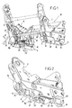
- the device according to the invention applies to a seat whose seat structure is composed of two subsets, respectively, left A and right B, forming base.
- Each of these subassemblies comprises a rigid flange 2, made of cast metal alloy, and whose lower part is in the form of a slider 3 which can circulate in a slideway 4.
- the slideway 4 is in the form of a C, that is to say is composed of a core 4a bordered by two wings 4b equipped, at their upper free end, an internal return 4c delimiting, with the return facing, a groove 5 .
- the bolts 8 and hooks 10 are hingedly mounted about horizontal and longitudinal axes 12 and 13, each associated with return means bringing them into the position of use, and are each provided with a vertical finger, not shown, cooperating with inclined ramps formed in an actuator or slide 14. It is slidably mounted longitudinally in the base between a rest position, in which it brings the hooks and latches in the working position, and a control position, opposite at the first and in which it causes the retraction of the hooks 10 and locks 8 inside a cover 15 inserted into the opening 5 of the slide. Each slide 14 is held in the rest position by a tension spring 16, visible in FIG. 1, and is brought into the control position by a mechanism comprising, as shown in FIGS.
- a lever 17, one of the ends 17a is hinged at 18 on the flange 2 of the base and whose other end 17b bears on the corresponding end of the slide 14 and, secondly, a gear or gear sector 19 s meshing with a toothed sector 17c of the lever 17.
- the toothed sector or gear 19 is integral with a shaft 20, which is rotatably mounted in a bearing of the corresponding flange 2 and which projects outside the flange to be linked in rotation to a control lever 22, visible in FIG. 1.
- the gear 19 is connected by a transverse shaft 23 to the gear 19 arranged in the other subassembly.
- the locks 8 are retracted below the base to release its locking in the slides, while allowing the adjustment of the longitudinal position of the seat on its slides.
- the invention therefore relates to a means of wedging in their slide of the two subsets A and B of a seat base equipped with locks 8 and retaining hooks 10.
- the ramp 35 is formed under the head 30a of the pin 30 and cooperates with a complementary ramp 36 protruding from the end face of a flange 32a of the bearing 32.
- This bearing is wedged in rotation by a protrusion 32b which is housed in a notch 37, formed at the edge of the bore for the bearing 32.
- the spring 34 is a torsion spring, and in particular a spiral spring whose one end 34a is connected to the flange 2 and the other end 34b is connected to the trunnion 30.
- the wedging member 33 has a generally rectangular shape and has a width less than the width of the groove 5 formed between the two internal returns 4c of the slide 4, and a longer length at this width.
- Figure 3 shows that it is plated on a shoulder 30b of the pin 30 by a nut system 40-washer 41 screwing on the lower free end of the pin and compressing against it, a sleeve 42 of viscoelastic material.
- This member 33 is connected in rotation to the pin 30 by a key or more simply by cooperation of flats, made in its bore, with complementary flats formed on the pin 30.
- each of the wedging members 33 is returned by its spring 34 in its working position, in which it is arranged transversely, as shown in Figure 3.
- the viscoelastic sleeve 42 can to compress by giving the trunnion 30 and the corresponding base, a slight vertical clearance, reducing the forces on the body 33.
- This device carries a pin 130 with a head 130a equipped with a pin 138 cooperating with a ramp 139 of the slide 14.
- the helical ramp 135 is not arranged on the head, but on each of the ends of the wedging member wedged to the lower end of the pin.
- the spring 134 for returning the member 133 is a helical torsion spring whose one end 134b is connected to the member 133, while the other end 134a is connected to the flange 2.
- the journal is freely mounted rotation in a bearing 132, made of plastic material and fitted in a vertical bore of the flanges 2.
- the wedging device functions in the same way, ie when the control handle disposed on the seat is released, the return spring 134 rotates the wedging member 133 by 90 ° so as to its ramps 135 come into contact with the inner face of the returns 4c of the slide 4 and immobilize in vertical translation, the connection of the base with its slides.
- Figure 6 shows that, as in the previous embodiment, the width of the member 133 allows it to enter the slide in the phase of introduction or extraction of the seat.
- the means for rotating the journal against its return spring are constituted by a finger cooperating with one or two ramps, but it is obvious that these means may have any other shape such as racks, or levers, provided that the trunnion can rotate 90 ° to bring the wedging member in vertical translation of its normal position of setting in its erasing position to pass in the groove 5 of the slide 4.
Landscapes
- Engineering & Computer Science (AREA)
- Aviation & Aerospace Engineering (AREA)
- Transportation (AREA)
- Mechanical Engineering (AREA)
- Seats For Vehicles (AREA)
- Chairs For Special Purposes, Such As Reclining Chairs (AREA)
- Body Structure For Vehicles (AREA)
Claims (5)
- Vorrichtung zum vertikalen Feststellen eines abnehmbaren verstellbaren Sitzes in C-förmigen Führungsschienen, bei der der Basisrahmen mit einer Fußanordnung fest verbunden ist, die durch zwei Untereinheiten, und zwar eine rechte (B) und eine linke (A) gebildet ist, die jeweils eine starre Wange (2) aufweisen, deren unterer Bereich als Schlitten ausgebildet ist, der in einer C-förmigen Führungsschiene (4) laufen kann, wobei jede Untereinheit Sperrklinken (8), die mit Unterschneidungen, Einkerbungen oder Rasten (9) der Führungsschiene zusammenwirken, und Rückhaltehaken (10) aufweist, die in der Lage sind, mit den inneren Unterschneidungen (4c) der Führungsschiene zusammenzuwirken, wenn der Sitz einer Aufprallenergie unterworfen ist, dadurch gekennzeichnet, dass sie in jeder Untereinheit aufweist:- einen vertikalen Lagerzapfen (30, 130), der drehbar in einem Lager (32, 132) der Fußanordnung angebracht ist,- ein Feststellorgan (33, 133) zum Feststellen bezüglich vertikaler Translation, das drehbar mit dem unteren Ende des Lagerzapfens (30, 130) verbunden ist und von oben gesehen eine allgemein rechteckige Form aufweist, deren kleinste Abmessung kleiner ist als die Breite der Nut der C-förmigen Führungsschiene, und dessen größte Abmessung größer ist als diese Breite, um in der Feststellposition unter die inneren Unterschneidungen der Führungsschiene kommen zu können,- eine Feder (34, 134), die das Feststellorgan stets in seine Feststellposition zurückstellt,- ein Mittel (38, 138), um den Lagerzapfen gegen seine Rückstellfeder bis zu einer Position drehen zu lassen, in der das Feststellorgan (33, 133) mit der Nut (5) der entsprechenden Führungsschiene (4) in Eingriff gebracht werden kann,- und zumindest eine schraubenförmige Rampe (35, 135), die mit dem Lagerzapfen (30, 130) drehverbunden ist und mit einem feststehenden komplementären Zapfen (36, 4c) zusammenwirkt, um das Feststellorgan vertikal zu verlagern und es in Berührung mit den Unterschneidungen der Führungsschiene (4) zu bringen.
- Vorrichtung zum vertikalen Feststellen eines abnehmbaren Sitzes nach Anspruch 1, dadurch gekennzeichnet, dass die Steuermittel für die Drehung des Lagerzapfens (30, 130) einen vertikalen Finger (38, 138) aufweisen, der von dem Kopf (30a, 130a) des Lagerzapfens nach oben vorspringt und eine einfache oder doppelte geneigte Rampe (39, 139), die in einer Kulisse (14) ausgebildet ist, die die Ausweichbewegungen der Sperrklinken (8) und der Haken (10) jeder der Untereinheiten (A, B) steuert.
- Vorrichtung zum vertikalen Feststellen eines abnehmbaren Sitzes nach Anspruch 1, dadurch gekennzeichnet, dass der Lagerzapfen (30) einen Kopf (30a) aufweist, unter dem die schraubenförmige Rampe (35) ausgebildet ist, während der komplementäre Zapfen (36), der mit dieser Rampe (35) zusammenwirkt, auf der Stirnseite eines Ringflansches (32a) ausgebildet ist, der an dem oberen Ende eines vertikalen Lagers (32) für den Lagerzapfen gebildet ist, wobei dieses Lager in die Fußanordnung eingebracht und bezüglich dieser gegen Drehung festgestellt wird.
- Vorrichtung zum vertikalen Feststellen eines abnehmbaren Sitzes nach Anspruch 1, dadurch gekennzeichnet, dass die schraubenförmige Rampe (135) auf der Oberseite jedes der Enden des Feststellorgans (133) gebildet ist und mit der geraden Innenseite der Unterschneidungen (4c) der Führungsschiene (4) zusammenwirkt.
- Vorrichtung zum vertikalen Feststellen eines abnehmbaren Sitzes nach Anspruch 1, dadurch gekennzeichnet, dass eine Muffe (42, 142) aus viskoelastischem Material in der Verbindung bezüglich vertikaler Translation zwischen dem Lagerzapfen (30, 130) und dem Feststellorgan (33, 133) angeordnet ist.
Applications Claiming Priority (2)
| Application Number | Priority Date | Filing Date | Title |
|---|---|---|---|
| FR0201797 | 2002-02-08 | ||
| FR0201797A FR2835790B1 (fr) | 2002-02-08 | 2002-02-08 | Dispositif de calage vertical et automatique d'un siege de vehicule |
Publications (3)
| Publication Number | Publication Date |
|---|---|
| EP1334865A2 EP1334865A2 (de) | 2003-08-13 |
| EP1334865A3 EP1334865A3 (de) | 2004-06-09 |
| EP1334865B1 true EP1334865B1 (de) | 2006-09-20 |
Family
ID=27589625
Family Applications (1)
| Application Number | Title | Priority Date | Filing Date |
|---|---|---|---|
| EP03356005A Expired - Lifetime EP1334865B1 (de) | 2002-02-08 | 2003-01-21 | Automatisch Vertikalverkeilungseinrichtung eines Fahrzeugsitzes |
Country Status (7)
| Country | Link |
|---|---|
| US (1) | US6736458B2 (de) |
| EP (1) | EP1334865B1 (de) |
| AT (1) | ATE340095T1 (de) |
| DE (1) | DE60308424T2 (de) |
| ES (1) | ES2272930T3 (de) |
| FR (1) | FR2835790B1 (de) |
| PT (1) | PT1334865E (de) |
Families Citing this family (42)
| Publication number | Priority date | Publication date | Assignee | Title |
|---|---|---|---|---|
| FR2855795B1 (fr) * | 2003-06-03 | 2006-02-17 | Faurecia Sieges Automobile | Dispositif de fixation, siege muni d'un tel dispositif, et vehicule muni d'un tel siege |
| FR2864481B1 (fr) * | 2003-12-26 | 2006-04-07 | Renault Sas | Agencement pour le montage d'un siege sur le plancher d'un vehicule au moyen de plots de guidage escamotables |
| US7021596B2 (en) * | 2004-02-11 | 2006-04-04 | Goodrich Corporation | Aircraft seat floor track quick release fitting |
| FR2900876B1 (fr) | 2006-05-12 | 2009-02-06 | Antolin Grupo Ing Sa | Profile de reception d'un siege et vehicule equipe de ce profile |
| US7427049B2 (en) * | 2006-07-24 | 2008-09-23 | Ami Industries, Inc. | Aircraft seat floor track fitting |
| DE102008038696A1 (de) * | 2007-11-20 | 2009-05-28 | C. Rob. Hammerstein Gmbh & Co. Kg | Gestell eines Kraftfahrzeugsitzes mit einem Gelenkbeschlag, insbesondere Rückenlehnengelenkbeschlag |
| EP2441672B1 (de) * | 2010-10-18 | 2013-04-03 | Diehl Service Modules GmbH | Vorrichtung zum Befestigen eines Ausstattungsgegenstands an einer Befestigungsstruktur eines Fahrzeugs |
| CN103085684B (zh) * | 2012-12-17 | 2015-03-18 | 湖北中航精机科技有限公司 | 一种汽车、汽车座椅及其滑轨机构 |
| DE102013200628A1 (de) * | 2013-01-17 | 2014-07-17 | Siemens Aktiengesellschaft | Befestigung einer Schienenfahrzeugkomponente auf einem Wagenkastendach eines Schienenfahrzeugwagenkastens |
| FR3006015B1 (fr) * | 2013-05-21 | 2016-01-08 | Peugeot Citroen Automobiles Sa | Dispositif d'ancrage d'equipement a verrouillage axial par excentrique et position variable continument |
| DE102016113409B4 (de) * | 2015-10-02 | 2022-06-30 | Tillmann Profil Gmbh | Schiene für einen Sitz eines Kraftfahrzeuges sowie Sitzschienensystem für ein Kraftfahrzeug |
| DE102016224663B4 (de) | 2015-12-15 | 2019-11-21 | Lear Corporation | Schienenanordnung |
| CN108426154B (zh) * | 2018-03-14 | 2019-01-15 | 江苏科华智能控制设备有限公司 | 一种稳定的信息安全测评系统 |
| US10882420B2 (en) | 2019-03-08 | 2021-01-05 | Lear Corporation | Track assembly |
| US11040639B2 (en) | 2018-05-04 | 2021-06-22 | Lear Corporation | Track assembly |
| US12233756B2 (en) | 2018-05-04 | 2025-02-25 | Lear Corporation | Track system with a support member |
| US11358497B2 (en) | 2018-05-04 | 2022-06-14 | Lear Corporation | Track system having a rolling member |
| US10906431B2 (en) | 2018-05-04 | 2021-02-02 | Lear Corporation | Track assembly |
| US11040638B2 (en) | 2018-05-04 | 2021-06-22 | Lear Corporation | Track assembly |
| US10926667B2 (en) | 2018-05-04 | 2021-02-23 | Lear Corporation | Track assembly |
| US10889208B2 (en) | 2018-05-04 | 2021-01-12 | Lear Corporation | Track assembly |
| DE102018207170B4 (de) * | 2018-05-08 | 2020-12-17 | Magna Seating (Germany) Gmbh | Kontaktierungssystem zum elektrischen Verbinden eines Bordnetzes eines Kraftfahrzeugs mit einem entnehmbaren Fahrzeugsitz oder einer Sitzanlage |
| US11225201B2 (en) | 2018-12-10 | 2022-01-18 | Lear Corporation | Track assembly |
| US11440482B2 (en) | 2018-12-10 | 2022-09-13 | Lear Corporation | Track assembly |
| US11117538B2 (en) | 2018-12-17 | 2021-09-14 | Lear Corporation | Electrical assembly |
| US11613220B2 (en) | 2018-12-17 | 2023-03-28 | Lear Corporation | Electrical assembly |
| US10855037B2 (en) | 2018-12-17 | 2020-12-01 | Lear Corporation | Support assembly with a support member and a track assembly |
| US10950977B2 (en) | 2018-12-18 | 2021-03-16 | Lear Corporation | Track assembly for a vehicle component |
| US11975665B2 (en) | 2019-02-20 | 2024-05-07 | Lear Corporation | Electrical assembly |
| US11040653B2 (en) | 2019-02-25 | 2021-06-22 | Lear Corporation | Track assembly |
| US11807142B2 (en) | 2019-03-06 | 2023-11-07 | Lear Corporation | Electrical track assembly |
| US11299075B2 (en) | 2019-03-06 | 2022-04-12 | Lear Corporation | Electrical assembly |
| TR201909535A2 (tr) * | 2019-06-26 | 2019-07-22 | Brusa Koltuk Ve Ic Trim Teknolojileri Sanayi Ve Ticaret Anonim Sirketi | Toplu taşima araçlari i̇çi̇n yolcu koltuğu hizli deği̇şti̇rme si̇stemi̇ |
| DE102019120194A1 (de) * | 2019-07-25 | 2021-01-28 | Aguti Produktentwicklung & Design Gmbh | Vorrichtung zur Anbringung einer Sitzanordnung in einem Fahrzeug und Fahrzeug |
| US11634101B2 (en) | 2019-10-04 | 2023-04-25 | Lear Corporation | Removable component system |
| US11323114B2 (en) | 2019-10-04 | 2022-05-03 | Lear Corporation | Electrical system |
| US11463083B2 (en) | 2019-10-04 | 2022-10-04 | Lear Corporation | Electrical system |
| DE102020102125A1 (de) | 2020-01-29 | 2021-07-29 | Bayerische Motoren Werke Aktiengesellschaft | Vorspannsystem für sitz |
| DE102021104018B4 (de) | 2020-02-21 | 2023-11-09 | Lear Corporation | Schienensystem mit einem Stützelement, Verfahren zum Betreiben eines Schienensystems |
| US12044301B2 (en) | 2020-02-21 | 2024-07-23 | Lear Corporation | Track system with a support member |
| US11505141B2 (en) | 2020-10-23 | 2022-11-22 | Lear Corporation | Electrical system with track assembly and support assembly |
| DE102021203819A1 (de) | 2021-04-16 | 2022-10-20 | Volkswagen Aktiengesellschaft | Klemmkörper und Befestigungsanordnung mit einem Klemmkörper |
Family Cites Families (16)
| Publication number | Priority date | Publication date | Assignee | Title |
|---|---|---|---|---|
| US3259354A (en) * | 1964-09-11 | 1966-07-05 | Beatrice L Dall | Seat track |
| US3445143A (en) * | 1967-05-22 | 1969-05-20 | Swenson Corp | Adjustable slide support |
| US4588226A (en) * | 1983-12-23 | 1986-05-13 | Erda, Inc. | Adjustable chair for aircraft and the like |
| US4575295A (en) * | 1984-01-11 | 1986-03-11 | Gte Products Corporation | Fastener for channeled structural members |
| US4830531A (en) * | 1985-10-04 | 1989-05-16 | Unistrut International Corp. | Unitary connection assembly for metal channels and method for assembly |
| US4729601A (en) * | 1987-03-26 | 1988-03-08 | Atr International, Inc. | Interlocking device for aircraft executive seats |
| JPH0639232B2 (ja) * | 1990-02-09 | 1994-05-25 | 株式会社大井製作所 | シートスライド装置 |
| DE4212694C2 (de) * | 1992-04-16 | 1995-09-21 | Daimler Benz Aerospace Airbus | Vorrichtung zur Verriegelung |
| DE4243185A1 (de) * | 1992-12-19 | 1994-06-23 | Hilti Ag | Befestigungsvorrichtung |
| CA2156971C (en) * | 1994-09-24 | 2001-08-21 | Richard C. Magnuson | Seat assembly for mass transit vehicle |
| FR2762812B3 (fr) * | 1997-04-30 | 1999-06-04 | Renault | Agencement pour le reglage de la position longitudinale et le blocage en position reglee d'un siege de vehicule automobile |
| FR2776582B1 (fr) * | 1998-03-30 | 2000-05-26 | Renault | Dispositif de reglage a cremaillere rapportee en fond de glissiere |
| US5823727A (en) * | 1998-04-02 | 1998-10-20 | Lee; Ray | Anchor fittings for securing objects on a elongated track |
| FR2777049B1 (fr) * | 1998-04-06 | 2000-06-02 | Renault | Systeme d'arrimage modulable a commande par cames |
| US6367758B1 (en) * | 1999-10-29 | 2002-04-09 | Dura Global Tachnologies | Snap-on torque tube for seat track assembly |
| FR2812251B1 (fr) * | 2000-07-27 | 2003-01-03 | Antolin Grupo Ing Sa | Dispositif de guidage et d'ancrage pour siege amovible de vehicule |
-
2002
- 2002-02-08 FR FR0201797A patent/FR2835790B1/fr not_active Expired - Fee Related
-
2003
- 2003-01-21 ES ES03356005T patent/ES2272930T3/es not_active Expired - Lifetime
- 2003-01-21 EP EP03356005A patent/EP1334865B1/de not_active Expired - Lifetime
- 2003-01-21 PT PT03356005T patent/PT1334865E/pt unknown
- 2003-01-21 DE DE60308424T patent/DE60308424T2/de not_active Expired - Lifetime
- 2003-01-21 AT AT03356005T patent/ATE340095T1/de not_active IP Right Cessation
- 2003-02-10 US US10/364,016 patent/US6736458B2/en not_active Expired - Fee Related
Also Published As
| Publication number | Publication date |
|---|---|
| DE60308424T2 (de) | 2007-09-20 |
| US6736458B2 (en) | 2004-05-18 |
| EP1334865A3 (de) | 2004-06-09 |
| EP1334865A2 (de) | 2003-08-13 |
| PT1334865E (pt) | 2006-12-29 |
| FR2835790A1 (fr) | 2003-08-15 |
| US20030151289A1 (en) | 2003-08-14 |
| ES2272930T3 (es) | 2007-05-01 |
| ATE340095T1 (de) | 2006-10-15 |
| FR2835790B1 (fr) | 2004-05-07 |
| DE60308424D1 (de) | 2006-11-02 |
Similar Documents
| Publication | Publication Date | Title |
|---|---|---|
| EP1334865B1 (de) | Automatisch Vertikalverkeilungseinrichtung eines Fahrzeugsitzes | |
| EP0945301B1 (de) | Gleitschiene für Fahrzeugsitz und mit solcher Schiene ausgerüsteter Sitz | |
| EP0931689B1 (de) | Kraftfahrzeugsitz, herausnehmbar, umwendbar und längsverstellbar | |
| FR2820696A1 (fr) | Siege de vehicule dote d'un dossier rabattable | |
| EP0947380B1 (de) | Auf dem Schienenboden eingebaute Zahnstangenvorrichtung | |
| FR2920360A1 (fr) | Siege de vehicule a appuie tete reglable en hauteur et cet appuie-tete | |
| EP0925996A1 (de) | Fahrzeugsitzeinheit mit auf Gleitschienen montiertem, abnehmbarem Sitz | |
| EP1067013A1 (de) | Vorrichtung zum Verstellen einer Sitzrückenlehne mit Doppelgelenk und einer einzelnen Betätigung | |
| EP0265316A1 (de) | Verriegelungssystem für eine lineare Schnellverstell- und Blockiereinrichtung eines beweglichen Teiles gegenüber einem festen Teil | |
| FR2606337A1 (fr) | Dispositif de reglage d'inclinaison, notamment pour siege de vehicule automobile | |
| FR2963586A1 (fr) | Glissiere pour siege de vehicule automobile a verrouillage lateral sans jeu | |
| EP0723889A1 (de) | Fahrzeugsitzgleitschiene | |
| EP0537057B1 (de) | Fahrzeugsitzleitschiene mit Festpunktrückführung | |
| EP3034723B1 (de) | Schloss für einen Öffnungsflügel eines Kraftfahrzeugs | |
| FR2777049A1 (fr) | Systeme d'arrimage modulable a commande par cames | |
| FR2524285A1 (fr) | Siege transformable, notamment de vehicule automobile | |
| FR2785240A1 (fr) | Glissiere pour siege amovible de vehicule, ensemble d'assise comprenant une telle glissiere, et vehicule equipe de telles glissieres | |
| EP0748916B1 (de) | Betätigungsvorrichtung für ein Tor oder andere Verschlussplatte | |
| EP0402195B1 (de) | Lösbare Befestigungsvorrichtung für einen Rücksitz eines Kraftfahrzeuges | |
| EP2137026A2 (de) | In einen kindersitz umwandelbarer automobilsitz mit dem rücken zur strasse und entsprechendes automobil | |
| EP3063035A1 (de) | Zurückziehbarer sitz für ein fahrzeug | |
| FR2463024A1 (fr) | Banquette arriere de vehicule | |
| EP3350016B1 (de) | Verriegelungsvorrichtung für zwei positionen einer hintersitz-rückenlehne eines kraftfahrzeugs | |
| FR2843080A1 (fr) | Securite pour siege de vehicule, rotatif et calable dans au moins deux positions | |
| EP2121377B1 (de) | Kippvorrichtung für eine sitzlehne |
Legal Events
| Date | Code | Title | Description |
|---|---|---|---|
| PUAI | Public reference made under article 153(3) epc to a published international application that has entered the european phase |
Free format text: ORIGINAL CODE: 0009012 |
|
| AK | Designated contracting states |
Designated state(s): AT BE BG CH CY CZ DE DK EE ES FI FR GB GR HU IE IT LI LU MC NL PT SE SI SK TR |
|
| AX | Request for extension of the european patent |
Extension state: AL LT LV MK RO |
|
| 17P | Request for examination filed |
Effective date: 20031014 |
|
| PUAL | Search report despatched |
Free format text: ORIGINAL CODE: 0009013 |
|
| AK | Designated contracting states |
Kind code of ref document: A3 Designated state(s): AT BE BG CH CY CZ DE DK EE ES FI FR GB GR HU IE IT LI LU MC NL PT SE SI SK TR |
|
| AX | Request for extension of the european patent |
Extension state: AL LT LV MK RO |
|
| RIC1 | Information provided on ipc code assigned before grant |
Ipc: 7B 60N 2/08 B Ipc: 7B 60N 2/015 A |
|
| AKX | Designation fees paid |
Designated state(s): AT BE BG CH CY CZ DE DK EE ES FI FR GB GR HU IE IT LI LU MC NL PT SE SI SK TR |
|
| GRAP | Despatch of communication of intention to grant a patent |
Free format text: ORIGINAL CODE: EPIDOSNIGR1 |
|
| GRAS | Grant fee paid |
Free format text: ORIGINAL CODE: EPIDOSNIGR3 |
|
| GRAA | (expected) grant |
Free format text: ORIGINAL CODE: 0009210 |
|
| AK | Designated contracting states |
Kind code of ref document: B1 Designated state(s): AT BE BG CH CY CZ DE DK EE ES FI FR GB GR HU IE IT LI LU MC NL PT SE SI SK TR |
|
| PG25 | Lapsed in a contracting state [announced via postgrant information from national office to epo] |
Ref country code: SI Free format text: LAPSE BECAUSE OF FAILURE TO SUBMIT A TRANSLATION OF THE DESCRIPTION OR TO PAY THE FEE WITHIN THE PRESCRIBED TIME-LIMIT Effective date: 20060920 Ref country code: IT Free format text: LAPSE BECAUSE OF FAILURE TO SUBMIT A TRANSLATION OF THE DESCRIPTION OR TO PAY THE FEE WITHIN THE PRESCRIBED TIME-LIMIT;WARNING: LAPSES OF ITALIAN PATENTS WITH EFFECTIVE DATE BEFORE 2007 MAY HAVE OCCURRED AT ANY TIME BEFORE 2007. THE CORRECT EFFECTIVE DATE MAY BE DIFFERENT FROM THE ONE RECORDED. Effective date: 20060920 Ref country code: AT Free format text: LAPSE BECAUSE OF FAILURE TO SUBMIT A TRANSLATION OF THE DESCRIPTION OR TO PAY THE FEE WITHIN THE PRESCRIBED TIME-LIMIT Effective date: 20060920 Ref country code: IE Free format text: LAPSE BECAUSE OF FAILURE TO SUBMIT A TRANSLATION OF THE DESCRIPTION OR TO PAY THE FEE WITHIN THE PRESCRIBED TIME-LIMIT Effective date: 20060920 Ref country code: FI Free format text: LAPSE BECAUSE OF FAILURE TO SUBMIT A TRANSLATION OF THE DESCRIPTION OR TO PAY THE FEE WITHIN THE PRESCRIBED TIME-LIMIT Effective date: 20060920 Ref country code: CZ Free format text: LAPSE BECAUSE OF FAILURE TO SUBMIT A TRANSLATION OF THE DESCRIPTION OR TO PAY THE FEE WITHIN THE PRESCRIBED TIME-LIMIT Effective date: 20060920 Ref country code: NL Free format text: LAPSE BECAUSE OF FAILURE TO SUBMIT A TRANSLATION OF THE DESCRIPTION OR TO PAY THE FEE WITHIN THE PRESCRIBED TIME-LIMIT Effective date: 20060920 Ref country code: SK Free format text: LAPSE BECAUSE OF FAILURE TO SUBMIT A TRANSLATION OF THE DESCRIPTION OR TO PAY THE FEE WITHIN THE PRESCRIBED TIME-LIMIT Effective date: 20060920 Ref country code: GB Free format text: LAPSE BECAUSE OF FAILURE TO SUBMIT A TRANSLATION OF THE DESCRIPTION OR TO PAY THE FEE WITHIN THE PRESCRIBED TIME-LIMIT Effective date: 20060920 |
|
| REG | Reference to a national code |
Ref country code: GB Ref legal event code: FG4D Free format text: NOT ENGLISH |
|
| REG | Reference to a national code |
Ref country code: CH Ref legal event code: EP |
|
| REG | Reference to a national code |
Ref country code: IE Ref legal event code: FG4D Free format text: LANGUAGE OF EP DOCUMENT: FRENCH |
|
| REF | Corresponds to: |
Ref document number: 60308424 Country of ref document: DE Date of ref document: 20061102 Kind code of ref document: P |
|
| PG25 | Lapsed in a contracting state [announced via postgrant information from national office to epo] |
Ref country code: BG Free format text: LAPSE BECAUSE OF FAILURE TO SUBMIT A TRANSLATION OF THE DESCRIPTION OR TO PAY THE FEE WITHIN THE PRESCRIBED TIME-LIMIT Effective date: 20061220 Ref country code: SE Free format text: LAPSE BECAUSE OF FAILURE TO SUBMIT A TRANSLATION OF THE DESCRIPTION OR TO PAY THE FEE WITHIN THE PRESCRIBED TIME-LIMIT Effective date: 20061220 Ref country code: DK Free format text: LAPSE BECAUSE OF FAILURE TO SUBMIT A TRANSLATION OF THE DESCRIPTION OR TO PAY THE FEE WITHIN THE PRESCRIBED TIME-LIMIT Effective date: 20061220 |
|
| REG | Reference to a national code |
Ref country code: PT Ref legal event code: SC4A Free format text: AVAILABILITY OF NATIONAL TRANSLATION Effective date: 20061107 |
|
| PG25 | Lapsed in a contracting state [announced via postgrant information from national office to epo] |
Ref country code: CH Free format text: LAPSE BECAUSE OF NON-PAYMENT OF DUE FEES Effective date: 20070131 Ref country code: MC Free format text: LAPSE BECAUSE OF NON-PAYMENT OF DUE FEES Effective date: 20070131 Ref country code: LI Free format text: LAPSE BECAUSE OF NON-PAYMENT OF DUE FEES Effective date: 20070131 |
|
| NLV1 | Nl: lapsed or annulled due to failure to fulfill the requirements of art. 29p and 29m of the patents act | ||
| REG | Reference to a national code |
Ref country code: IE Ref legal event code: FD4D |
|
| REG | Reference to a national code |
Ref country code: ES Ref legal event code: FG2A Ref document number: 2272930 Country of ref document: ES Kind code of ref document: T3 |
|
| PLBE | No opposition filed within time limit |
Free format text: ORIGINAL CODE: 0009261 |
|
| STAA | Information on the status of an ep patent application or granted ep patent |
Free format text: STATUS: NO OPPOSITION FILED WITHIN TIME LIMIT |
|
| 26N | No opposition filed |
Effective date: 20070621 |
|
| REG | Reference to a national code |
Ref country code: CH Ref legal event code: PL |
|
| BERE | Be: lapsed |
Owner name: GRUPO ANTOLIN-INGENIERIA, S.A. Effective date: 20070131 |
|
| PG25 | Lapsed in a contracting state [announced via postgrant information from national office to epo] |
Ref country code: BE Free format text: LAPSE BECAUSE OF NON-PAYMENT OF DUE FEES Effective date: 20070131 |
|
| PG25 | Lapsed in a contracting state [announced via postgrant information from national office to epo] |
Ref country code: GR Free format text: LAPSE BECAUSE OF FAILURE TO SUBMIT A TRANSLATION OF THE DESCRIPTION OR TO PAY THE FEE WITHIN THE PRESCRIBED TIME-LIMIT Effective date: 20061221 |
|
| PG25 | Lapsed in a contracting state [announced via postgrant information from national office to epo] |
Ref country code: EE Free format text: LAPSE BECAUSE OF FAILURE TO SUBMIT A TRANSLATION OF THE DESCRIPTION OR TO PAY THE FEE WITHIN THE PRESCRIBED TIME-LIMIT Effective date: 20060920 |
|
| PG25 | Lapsed in a contracting state [announced via postgrant information from national office to epo] |
Ref country code: CY Free format text: LAPSE BECAUSE OF FAILURE TO SUBMIT A TRANSLATION OF THE DESCRIPTION OR TO PAY THE FEE WITHIN THE PRESCRIBED TIME-LIMIT Effective date: 20060920 Ref country code: LU Free format text: LAPSE BECAUSE OF NON-PAYMENT OF DUE FEES Effective date: 20070121 |
|
| PG25 | Lapsed in a contracting state [announced via postgrant information from national office to epo] |
Ref country code: HU Free format text: LAPSE BECAUSE OF FAILURE TO SUBMIT A TRANSLATION OF THE DESCRIPTION OR TO PAY THE FEE WITHIN THE PRESCRIBED TIME-LIMIT Effective date: 20070321 Ref country code: TR Free format text: LAPSE BECAUSE OF FAILURE TO SUBMIT A TRANSLATION OF THE DESCRIPTION OR TO PAY THE FEE WITHIN THE PRESCRIBED TIME-LIMIT Effective date: 20060920 |
|
| PGFP | Annual fee paid to national office [announced via postgrant information from national office to epo] |
Ref country code: PT Payment date: 20111215 Year of fee payment: 10 |
|
| PGFP | Annual fee paid to national office [announced via postgrant information from national office to epo] |
Ref country code: IT Payment date: 20120125 Year of fee payment: 10 |
|
| PGFP | Annual fee paid to national office [announced via postgrant information from national office to epo] |
Ref country code: ES Payment date: 20120126 Year of fee payment: 10 |
|
| REG | Reference to a national code |
Ref country code: PT Ref legal event code: MM4A Free format text: LAPSE DUE TO NON-PAYMENT OF FEES Effective date: 20130722 |
|
| PG25 | Lapsed in a contracting state [announced via postgrant information from national office to epo] |
Ref country code: PT Free format text: LAPSE BECAUSE OF NON-PAYMENT OF DUE FEES Effective date: 20130722 |
|
| PG25 | Lapsed in a contracting state [announced via postgrant information from national office to epo] |
Ref country code: IT Free format text: LAPSE BECAUSE OF NON-PAYMENT OF DUE FEES Effective date: 20130121 |
|
| REG | Reference to a national code |
Ref country code: ES Ref legal event code: FD2A Effective date: 20140321 |
|
| PG25 | Lapsed in a contracting state [announced via postgrant information from national office to epo] |
Ref country code: ES Free format text: LAPSE BECAUSE OF NON-PAYMENT OF DUE FEES Effective date: 20130122 |
|
| REG | Reference to a national code |
Ref country code: FR Ref legal event code: PLFP Year of fee payment: 14 |
|
| REG | Reference to a national code |
Ref country code: FR Ref legal event code: PLFP Year of fee payment: 15 |
|
| REG | Reference to a national code |
Ref country code: DE Ref legal event code: R082 Ref document number: 60308424 Country of ref document: DE Representative=s name: WITTE, WELLER & PARTNER PATENTANWAELTE MBB, DE Ref country code: DE Ref legal event code: R081 Ref document number: 60308424 Country of ref document: DE Owner name: LEAR CORP. (N.D.GES.D. STAATES DELAWARE), SOUT, US Free format text: FORMER OWNER: GRUPO ANTOLIN-INGENIERIA S.A., BURGOS, ES |
|
| REG | Reference to a national code |
Ref country code: FR Ref legal event code: TP Owner name: LEAR CORPORATION, US Effective date: 20171127 |
|
| REG | Reference to a national code |
Ref country code: FR Ref legal event code: PLFP Year of fee payment: 16 |
|
| PGFP | Annual fee paid to national office [announced via postgrant information from national office to epo] |
Ref country code: DE Payment date: 20220127 Year of fee payment: 20 |
|
| PGFP | Annual fee paid to national office [announced via postgrant information from national office to epo] |
Ref country code: FR Payment date: 20220125 Year of fee payment: 20 |
|
| REG | Reference to a national code |
Ref country code: DE Ref legal event code: R071 Ref document number: 60308424 Country of ref document: DE |