EP1334865B1 - Veritcal and automatic alignment device for a vehicle seat - Google Patents
Veritcal and automatic alignment device for a vehicle seat Download PDFInfo
- Publication number
- EP1334865B1 EP1334865B1 EP03356005A EP03356005A EP1334865B1 EP 1334865 B1 EP1334865 B1 EP 1334865B1 EP 03356005 A EP03356005 A EP 03356005A EP 03356005 A EP03356005 A EP 03356005A EP 1334865 B1 EP1334865 B1 EP 1334865B1
- Authority
- EP
- European Patent Office
- Prior art keywords
- wedging
- journal
- slideway
- vertical
- returns
- Prior art date
- Legal status (The legal status is an assumption and is not a legal conclusion. Google has not performed a legal analysis and makes no representation as to the accuracy of the status listed.)
- Expired - Lifetime
Links
Images


Classifications
-
- B—PERFORMING OPERATIONS; TRANSPORTING
- B60—VEHICLES IN GENERAL
- B60N—SEATS SPECIALLY ADAPTED FOR VEHICLES; VEHICLE PASSENGER ACCOMMODATION NOT OTHERWISE PROVIDED FOR
- B60N2/00—Seats specially adapted for vehicles; Arrangement or mounting of seats in vehicles
- B60N2/005—Arrangement or mounting of seats in vehicles, e.g. dismountable auxiliary seats
- B60N2/015—Attaching seats directly to vehicle chassis
- B60N2/01508—Attaching seats directly to vehicle chassis using quick release attachments
- B60N2/01516—Attaching seats directly to vehicle chassis using quick release attachments with locking mechanisms
- B60N2/01558—Attaching seats directly to vehicle chassis using quick release attachments with locking mechanisms with key and slot
- B60N2/01566—Attaching seats directly to vehicle chassis using quick release attachments with locking mechanisms with key and slot key rotating about a vertical axis
-
- B—PERFORMING OPERATIONS; TRANSPORTING
- B60—VEHICLES IN GENERAL
- B60N—SEATS SPECIALLY ADAPTED FOR VEHICLES; VEHICLE PASSENGER ACCOMMODATION NOT OTHERWISE PROVIDED FOR
- B60N2/00—Seats specially adapted for vehicles; Arrangement or mounting of seats in vehicles
- B60N2/005—Arrangement or mounting of seats in vehicles, e.g. dismountable auxiliary seats
- B60N2/015—Attaching seats directly to vehicle chassis
- B60N2/01508—Attaching seats directly to vehicle chassis using quick release attachments
- B60N2/01516—Attaching seats directly to vehicle chassis using quick release attachments with locking mechanisms
- B60N2/01525—Attaching seats directly to vehicle chassis using quick release attachments with locking mechanisms with locking elements expanding inside or under the vehicle floor or rail
- B60N2/01541—Attaching seats directly to vehicle chassis using quick release attachments with locking mechanisms with locking elements expanding inside or under the vehicle floor or rail using moving hooks
-
- B—PERFORMING OPERATIONS; TRANSPORTING
- B60—VEHICLES IN GENERAL
- B60N—SEATS SPECIALLY ADAPTED FOR VEHICLES; VEHICLE PASSENGER ACCOMMODATION NOT OTHERWISE PROVIDED FOR
- B60N2/00—Seats specially adapted for vehicles; Arrangement or mounting of seats in vehicles
- B60N2/24—Seats specially adapted for vehicles; Arrangement or mounting of seats in vehicles for particular purposes or particular vehicles
- B60N2/42—Seats specially adapted for vehicles; Arrangement or mounting of seats in vehicles for particular purposes or particular vehicles the seat constructed to protect the occupant from the effect of abnormal g-forces, e.g. crash or safety seats
Definitions
- the invention relates to a vertical and automatic wedging device in C-rails of a removable vehicle seat. It relates more particularly to the removable seats comprising, on the one hand, positioning means in longitudinal rails fixed to the floor of the vehicle, on the other hand, retaining hooks, adapted to cooperate with the internal returns of the slide when the seat is subjected to shock energy and, in addition, means for adjusting their longitudinal position, with locking in the chosen position.
- Document EP 1 176 047 discloses a guiding and anchoring device for a seat that is removable relative to two parallel longitudinal rails fixed to the floor of a vehicle.
- each of the right or left subassemblies of the seat is equipped with a wedging member which is normally in the wedging position, but which, when the slides fitted to this seat are inserted into slides, is brought into position. introduction into these slides.
- the return spring associated with each of them returns them to the rest position, in which position the organ wedging is arranged transversely to the groove of each slide.
- each pin bears with a complementary bearing and causes the vertical displacement of the pin, which has the effect of causing the wedging member in contact with the lower face of the returns of the slide in which it is arranged, thereby ensuring the positive connection of the seat with its slides.
- the base is linked to the slides to suppress the generation of all noises and all vertical displacements, but also horizontal because of the clearance between the locks and the locks. housing receiving them.
- the means for controlling the rotation of the trunnion comprise a vertical finger projecting upwardly from the head of this trunnion and an inclined ramp, single or double, formed in a slide controlling the retraction movements of the latches and latches. hooks of each of the sliders.
- the operator actuates the means arranged on the seat, to bring the latches and the hooks in the retracted position, for example before engaging the sliders of the legs in the grooves C of the slides, it controls the pivoting of the journal to against its biasing means and allows the wedging member to move from its stalling position to its retracted position promoting its engagement in the slide.
- the trunnion comprises a head under which is formed the helical ramp, while the complementary bearing cooperating with this ramp is formed on the end face of a collar formed at the upper end. a vertical bearing for the pin, this bearing being reported in the base and wedged in rotation relative thereto.
- the helical ramp is formed on the upper face of each of the ends of the wedging member and cooperates with the rectilinear inner face of the C returns of the slide.
- the device according to the invention applies to a seat whose seat structure is composed of two subsets, respectively, left A and right B, forming base.
- Each of these subassemblies comprises a rigid flange 2, made of cast metal alloy, and whose lower part is in the form of a slider 3 which can circulate in a slideway 4.
- the slideway 4 is in the form of a C, that is to say is composed of a core 4a bordered by two wings 4b equipped, at their upper free end, an internal return 4c delimiting, with the return facing, a groove 5 .
- the bolts 8 and hooks 10 are hingedly mounted about horizontal and longitudinal axes 12 and 13, each associated with return means bringing them into the position of use, and are each provided with a vertical finger, not shown, cooperating with inclined ramps formed in an actuator or slide 14. It is slidably mounted longitudinally in the base between a rest position, in which it brings the hooks and latches in the working position, and a control position, opposite at the first and in which it causes the retraction of the hooks 10 and locks 8 inside a cover 15 inserted into the opening 5 of the slide. Each slide 14 is held in the rest position by a tension spring 16, visible in FIG. 1, and is brought into the control position by a mechanism comprising, as shown in FIGS.
- a lever 17, one of the ends 17a is hinged at 18 on the flange 2 of the base and whose other end 17b bears on the corresponding end of the slide 14 and, secondly, a gear or gear sector 19 s meshing with a toothed sector 17c of the lever 17.
- the toothed sector or gear 19 is integral with a shaft 20, which is rotatably mounted in a bearing of the corresponding flange 2 and which projects outside the flange to be linked in rotation to a control lever 22, visible in FIG. 1.
- the gear 19 is connected by a transverse shaft 23 to the gear 19 arranged in the other subassembly.
- the locks 8 are retracted below the base to release its locking in the slides, while allowing the adjustment of the longitudinal position of the seat on its slides.
- the invention therefore relates to a means of wedging in their slide of the two subsets A and B of a seat base equipped with locks 8 and retaining hooks 10.
- the ramp 35 is formed under the head 30a of the pin 30 and cooperates with a complementary ramp 36 protruding from the end face of a flange 32a of the bearing 32.
- This bearing is wedged in rotation by a protrusion 32b which is housed in a notch 37, formed at the edge of the bore for the bearing 32.
- the spring 34 is a torsion spring, and in particular a spiral spring whose one end 34a is connected to the flange 2 and the other end 34b is connected to the trunnion 30.
- the wedging member 33 has a generally rectangular shape and has a width less than the width of the groove 5 formed between the two internal returns 4c of the slide 4, and a longer length at this width.
- Figure 3 shows that it is plated on a shoulder 30b of the pin 30 by a nut system 40-washer 41 screwing on the lower free end of the pin and compressing against it, a sleeve 42 of viscoelastic material.
- This member 33 is connected in rotation to the pin 30 by a key or more simply by cooperation of flats, made in its bore, with complementary flats formed on the pin 30.
- each of the wedging members 33 is returned by its spring 34 in its working position, in which it is arranged transversely, as shown in Figure 3.
- the viscoelastic sleeve 42 can to compress by giving the trunnion 30 and the corresponding base, a slight vertical clearance, reducing the forces on the body 33.
- This device carries a pin 130 with a head 130a equipped with a pin 138 cooperating with a ramp 139 of the slide 14.
- the helical ramp 135 is not arranged on the head, but on each of the ends of the wedging member wedged to the lower end of the pin.
- the spring 134 for returning the member 133 is a helical torsion spring whose one end 134b is connected to the member 133, while the other end 134a is connected to the flange 2.
- the journal is freely mounted rotation in a bearing 132, made of plastic material and fitted in a vertical bore of the flanges 2.
- the wedging device functions in the same way, ie when the control handle disposed on the seat is released, the return spring 134 rotates the wedging member 133 by 90 ° so as to its ramps 135 come into contact with the inner face of the returns 4c of the slide 4 and immobilize in vertical translation, the connection of the base with its slides.
- Figure 6 shows that, as in the previous embodiment, the width of the member 133 allows it to enter the slide in the phase of introduction or extraction of the seat.
- the means for rotating the journal against its return spring are constituted by a finger cooperating with one or two ramps, but it is obvious that these means may have any other shape such as racks, or levers, provided that the trunnion can rotate 90 ° to bring the wedging member in vertical translation of its normal position of setting in its erasing position to pass in the groove 5 of the slide 4.
Landscapes
- Engineering & Computer Science (AREA)
- Aviation & Aerospace Engineering (AREA)
- Transportation (AREA)
- Mechanical Engineering (AREA)
- Seats For Vehicles (AREA)
- Chairs For Special Purposes, Such As Reclining Chairs (AREA)
- Body Structure For Vehicles (AREA)
Abstract
Description
L'invention est relative à un dispositif de calage vertical et automatique dans des glissières en C d'un siège amovible de véhicule. Elle concerne plus spécialement les sièges amovibles comportant, d'une part, des moyens de positionnement dans des glissières longitudinales fixées au plancher du véhicule, d'autre part, des crochets de retenue, aptes à coopérer avec les retours internes de la glissière lorsque le siège est soumis à une énergie de choc et, de plus, des moyens permettant de régler leur position longitudinale, avec verrouillage dans la position choisie.The invention relates to a vertical and automatic wedging device in C-rails of a removable vehicle seat. It relates more particularly to the removable seats comprising, on the one hand, positioning means in longitudinal rails fixed to the floor of the vehicle, on the other hand, retaining hooks, adapted to cooperate with the internal returns of the slide when the seat is subjected to shock energy and, in addition, means for adjusting their longitudinal position, with locking in the chosen position.
Dans ces sièges, la structure d'assise est solidaire d'un piètement formé par deux sous ensembles, respectivement droite et gauche, comprenant chacun un flasque rigide dont la partie inférieure est aménagée en forme de coulisseau pour circuler dans une glissière en C, et portés, par ce coulisseau :
- des verrous, coopérant avec retours, crans ou encoches de la glissière,
- des crochets de retenue,
- et un actionneur relié à des moyens de commande portés par le siège et à des moyens de rappel, pour commander les mouvements des verrous et des crochets.
- latches, cooperating with returns, notches or notches of the slide,
- restraining hooks,
- and an actuator connected to control means carried by the seat and to return means for controlling the movements of the locks and hooks.
On connaît par le document EP 1 176 047 un dispositif de guidage et d'ancrage pour siège amovible par rapport à deux glissières longitudinales parallèles fixées au plancher d'un véhicule.Document EP 1 176 047 discloses a guiding and anchoring device for a seat that is removable relative to two parallel longitudinal rails fixed to the floor of a vehicle.
Malgré le soin apporté à la fabrication des composants du piètement, à l'assemblage de ces composants et à la pose des glissières, le cumul des tolérances de fabrication peut, dans certaines combinaisons sièges-glissières, former des jeux verticaux qui, même lorsque le siège est calé et verrouillé dans ses glissières, favorisent des déplacements verticaux de faible ampleur, mais générateurs de bruit et d'inconfort pour l'occupant.Despite the care taken in the manufacture of the components of the base, the assembly of these components and the installation of the slides, the accumulation of manufacturing tolerances can, in certain combinations of seats and slides, form vertical games which, even when the seat is wedged and locked in its slides, promote vertical movements of small magnitude, but generating noise and discomfort for the occupant.
La présente invention a pour objet de remédier à cela en fournissant un dispositif de calage vertical automatique du piètement d'un siège dans ses glissières.The present invention aims to remedy this by providing an automatic vertical wedging device of the base of a seat in its slides.
Ce dispositif de calage comprend :
- un tourillon vertical monté rotatif dans un palier du piètement,
- un organe de calage en translation vertical, lié en rotation à l'extrémité inférieure du tourillon et présentant, en vue par-dessus, une forme générale rectangulaire dont la plus petite dimension est inférieure à la largeur de la rainure de la glissière en C et dont la plus grande dimension est supérieure à cette largeur, pour pouvoir, en position de calage, venir sous les retours internes de la glissière,
- un ressort rappelant constamment l'organe de calage dans sa position de calage,
- un moyen pour faire pivoter le tourillon à l'encontre de son ressort de rappel jusqu'à une position dans laquelle l'organe de calage peut être engagé dans la rainure de la glissière correspondante,
- et au moins une rampe hélicoïdale qui, liée en rotation au tourillon, coopère avec une portée complémentaire fixe pour déplacer verticalement l'organe de calage et l'amener au contact des retours de la glissière.
- a vertical journal rotatably mounted in a bearing of the base,
- a vertical translational locking member, rotatably connected to the lower end of the trunnion and having, in view from above, a generally rectangular shape whose smaller dimension is smaller than the width of the groove of the slideway C and whose greatest dimension is greater than this width, in order to be able to come under the internal returns of the slide,
- a spring constantly biasing the wedging member in its wedging position,
- means for pivoting the journal against its return spring to a position in which the wedging member can be engaged in the groove of the corresponding slide,
- and at least one helical ramp which, linked in rotation with the trunnion, cooperates with a fixed complementary surface to vertically move the wedging member and bring it into contact with the returns of the slideway.
Ainsi, chacun des sous-ensembles droit ou gauche du siège est équipé d'un organe de calage qui est normalement en position de calage, mais qui, lors de l'introduction des coulisseaux équipant ce siège dans des glissières, est amené en position d'introduction dans ces glissières. Dès que le siège est positionné dans celle-ci et que l'opérateur cesse d'actionner les moyens de commande des tourillons, le ressort de rappel associé à chacun d'eux les ramènent en position de repos, position dans laquelle l'organe de calage est disposée transversalement à la rainure de chaque glissière. Durant cette rotation, la rampe hélicoïdale de chaque tourillon vient en appui avec une portée complémentaire et provoque le déplacement vertical du tourillon, ce qui a pour effet d'amener l'organe de calage au contact de la face inférieure des retours de la glissière dans laquelle il est disposé, en assurant ainsi la liaison positive du siège avec ses glissières.Thus, each of the right or left subassemblies of the seat is equipped with a wedging member which is normally in the wedging position, but which, when the slides fitted to this seat are inserted into slides, is brought into position. introduction into these slides. As soon as the seat is positioned in the latter and the operator stops actuating the control means of the journals, the return spring associated with each of them returns them to the rest position, in which position the organ wedging is arranged transversely to the groove of each slide. During this rotation, the helical ramp of each pin bears with a complementary bearing and causes the vertical displacement of the pin, which has the effect of causing the wedging member in contact with the lower face of the returns of the slide in which it is arranged, thereby ensuring the positive connection of the seat with its slides.
Il en résulte que, quels que soient les jeux fonctionnels résultant de la dispersion des tolérances de fabrication, le piètement est lié aux glissières pour supprimer la génération de tous bruits et tous déplacements verticaux, mais aussi horizontaux en raison du jeu entre les verrous et les logements les recevant.As a result, regardless of the functional clearances resulting from the dispersion of manufacturing tolerances, the base is linked to the slides to suppress the generation of all noises and all vertical displacements, but also horizontal because of the clearance between the locks and the locks. housing receiving them.
Avantageusement, les moyens de commande de la rotation du tourillon comprennent un doigt vertical, saillant vers le haut, depuis la tête de ce tourillon et une rampe inclinée, simple ou double, ménagée dans une coulisse commandant les mouvements d'escamotage des verrous et des crochets de chacun des coulisseaux.Advantageously, the means for controlling the rotation of the trunnion comprise a vertical finger projecting upwardly from the head of this trunnion and an inclined ramp, single or double, formed in a slide controlling the retraction movements of the latches and latches. hooks of each of the sliders.
Ainsi, en même temps que l'opérateur actionne les moyens disposés sur le siège, pour amener les verrous et les crochets en position de rétraction, par exemple avant d'engager les coulisseaux des piètements dans les rainures en C des glissières, il commande le pivotement du tourillon à l'encontre de ses moyens de rappel et permet, à l'organe de calage, de passer de sa position de calage à sa position d'escamotage favorisant son engagement dans la glissière.Thus, at the same time that the operator actuates the means arranged on the seat, to bring the latches and the hooks in the retracted position, for example before engaging the sliders of the legs in the grooves C of the slides, it controls the pivoting of the journal to against its biasing means and allows the wedging member to move from its stalling position to its retracted position promoting its engagement in the slide.
Dans une forme d'exécution de l'invention, le tourillon comporte une tête sous laquelle est ménagée la rampe hélicoïdale, tandis que la portée complémentaire coopérant avec cette rampe est ménagée sur la face en bout d'une collerette formée à l'extrémité supérieure d'un palier vertical pour le tourillon, ce palier étant rapporté dans le piètement et calé en rotation par rapport à lui.In one embodiment of the invention, the trunnion comprises a head under which is formed the helical ramp, while the complementary bearing cooperating with this ramp is formed on the end face of a collar formed at the upper end. a vertical bearing for the pin, this bearing being reported in the base and wedged in rotation relative thereto.
Dans une autre forme d'exécution, la rampe hélicoïdale est formée sur la face supérieure de chacune des extrémités de l'organe de calage et coopère avec la face interne rectiligne des retours en C de la glissière.In another embodiment, the helical ramp is formed on the upper face of each of the ends of the wedging member and cooperates with the rectilinear inner face of the C returns of the slide.
D'autres caractéristiques et avantages ressortiront de la description qui suit en référence au dessin schématique annexé représentant deux formes d'exécution du dispositif de calage.
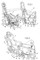
- Figure 1 est une vue en perspective de la partie inférieure d'une armature de siège,
- Figure 2 est une vue partielle, en perspective, du piètement droit d'un siège, lorsque les capots de protection du coulisseau sont enlevés,
- Figure 3 est une vue en coupe transversale d'une première forme d'exécution du dispositif de calage, lorsqu'il est en position de calage,
- Figure 4 est une vue partielle, en perspective, des éléments essentiels du dispositif de calage de figure 3,
- Figure 5 est une vue en coupe transversale d'une autre forme d'exécution du dispositif de calage, lorsqu'il est en position de calage,
- Figure 6 est une vue partielle en perspective du dispositif de calage de figure 5 et de sa coulisse de commande.
- Figure 1 is a perspective view of the lower part of a seat frame,
- Figure 2 is a partial view, in perspective, of the right base of a seat, when the protective covers of the slide are removed,
- 3 is a cross-sectional view of a first embodiment of the wedging device, when it is in the wedging position,
- FIG. 4 is a partial view, in perspective, of the essential elements of the wedging device of FIG. 3,
- FIG. 5 is a cross-sectional view of another embodiment of the wedging device, when it is in the wedging position,
- Figure 6 is a partial perspective view of the wedging device of Figure 5 and its control slide.
Comme montré à la figure 1, le dispositif selon l'invention s'applique à un siège dont la structure d'assise est composée de deux sous ensembles, respectivement, gauche A et droit B, formant piètement. Chacun de ces sous ensembles comprend un flasque rigide 2, réalisé en alliage métallique moulé, et dont la partie inférieure est en forme de coulisseau 3 pouvant circuler dans une glissière 4. Comme montré aux figures 3 et 5, la glissière 4 est en forme de C, c'est-à-dire est composée d'une âme 4a bordée par deux ailes 4b équipées, à leur extrémité libre supérieure, d'un retour interne 4c délimitant, avec le retour en vis-à-vis, une rainure 5.As shown in Figure 1, the device according to the invention applies to a seat whose seat structure is composed of two subsets, respectively, left A and right B, forming base. Each of these subassemblies comprises a rigid flange 2, made of cast metal alloy, and whose lower part is in the form of a
Chaque sous ensemble du piètement comporte une structure interne portant directement, ou par l'intermédiaire de chariots 6a, 6b, comme montré à la figure 2 :
- des
galets 7, aptes à rouler sur les retours 4c de la glissière, - des
verrous 8 dont les dents 8a sont aptes à coopérer avec des lumières 9 ménagées dans lesailes 4b de la glissière, - et de
crochets 10 aptes à venir au-dessous des retours internes 4c de la glissière pour retenir le piètement et le siège en cas de choc tendant à soulever le siège et son occupant.
-
rollers 7, able to roll on the returns 4c of the slide, -
locks 8 whose teeth 8a are adapted to cooperate with lights 9 formed in theflanges 4b of the slideway, - and
hooks 10 adapted to come below the internal returns 4c of the slide to retain the base and the seat in case of shock tending to lift the seat and its occupant.
Les verrous 8 et crochets 10 sont montés à articulation autour d'axes horizontaux et longitudinaux 12 et 13, sont chacun associés à des moyens de rappel les amenant en position d'utilisation, et sont chacun munis d'un doigt vertical, non représenté, coopérant avec des rampes inclinées ménagées dans un actionneur ou coulisse 14. Celle-ci est montée coulissante longitudinalement dans le piètement entre une position de repos, dans laquelle elle amène les crochets et les verrous en position de travail, et une position de commande, opposée à la première et dans laquelle elle provoque la rétraction des crochets 10 et des verrous 8 à l'intérieur d'un capot 15 s'insérant dans l'ouverture 5 de la glissière. Chaque coulisse 14 est maintenue en position de repos par un ressort de traction 16, visible à la figure 1, et est amenée en position de commande par un mécanisme comprenant, comme montré figures 1 et 4, d'une part, un levier 17, dont l'une des extrémités 17a est articulée en 18 sur le flasque 2 du piètement et dont l'autre extrémité 17b est en appui sur l'extrémité correspondante de la coulisse 14 et, d'autre part, un engrenage ou secteur denté 19 s'engrenant avec un secteur denté 17c du levier 17. Le secteur denté ou engrenage 19 est solidaire d'un arbre 20, qui est monté libre en rotation dans un palier du flasque 2 correspondant et qui dépasse à l'extérieur de ce flasque pour être lié en rotation à un levier de commande 22, visible figure 1. Dans la forme d'exécution représentée à la figure 1, l'engrenage 19 est lié par un arbre transversal 23 à l'engrenage 19 disposé dans l'autre sous ensemble.The
On conçoit aisément que l'actionnement du levier 22 dans le sens de la flèche 21 provoque le pivotement dans le même sens du levier 17 et, en conséquence, le déplacement avec démultiplication de la coulisse 14 dans le sens de la flèche 24.It is easy to conceive that the actuation of the lever 22 in the direction of the arrow 21 causes the pivoting in the same direction of the
Dans une première phase du déplacement, les verrous 8 sont rétractés au-dessous du piètement pour libérer son verrouillage dans les glissières, tout en permettant le réglage de la position longitudinale du siège sur ses glissières.In a first phase of the displacement, the
Dans une deuxième phase, et si la course de la coulisse 14 est poursuivie, ce sont les crochets 10 qui s'escamotent et viennent dans l'encombrement du capot 14 pour permettre l'extraction du siège de ses glissières.In a second phase, and if the stroke of the
Lorsque le levier 22 est relâché, les ressorts de traction 16, disposés dans chacun des sous ensembles gauche A et droit B, ramènent le levier 22 et les coulisses 14 à leur position de départ. Ces divers moyens sont décrits plus en détails dans la demande de brevet européen n°01420158.6 au nom de la déposante. N'ayant en commun avec la présente invention que la coulisse 14, il ne paraît pas nécessaire de les décrire plus en détails.When the lever 22 is released, the traction springs 16, arranged in each of the left subsets A and B right, bring the lever 22 and the
L'invention porte donc sur un moyen de calage dans leur glissière des deux sous ensembles A et B d'un piètement de siège équipé de verrous 8 et de crochets de retenue 10.The invention therefore relates to a means of wedging in their slide of the two subsets A and B of a seat base equipped with
Dans la forme d'exécution représentée aux figures 3 à 4, le dispositif de calage comprend :
un tourillon 30 d'axe vertical, monté libre en rotationdans un palier 32 en matière plastique disposé dans un alésage vertical de la partie inférieure du flasque 2,un organe 33 de calage en translation vertical, calé en rotation à l'extrémité inférieure du tourillon 30,- un ressort de rappel 34,
- et une rampe hélicoïdale 35.
- a
pin 30 of vertical axis, rotatably mounted in aplastic bearing 32 disposed in a vertical bore of the lower portion of the flange 2, - a
member 33 for wedging in vertical translation, set in rotation at the lower end of thejournal 30, - a return spring 34,
- and a
helical ramp 35.
Dans cette forme d'exécution, la rampe 35 est ménagée sous la tête 30a du tourillon 30 et coopère avec une rampe complémentaire 36, saillant de la face en bout d'une collerette 32a du palier 32. Ce palier est calé en rotation par une excroissance 32b qui se loge dans une encoche 37, ménagée en bordure de l'alésage pour le palier 32.In this embodiment, the
La tête 30a du tourillon 30 comporte, en saillie vers le haut, un doigt vertical 38 qui coopère avec une rampe 39, ménagée dans la coulisse 14.The head 30a of the
Le ressort 34 est un ressort de torsion, et notamment un ressort en spirale dont l'une des extrémités 34a est liée au flasque 2 et dont l'autre extrémité 34b est liée au tourillon 30.The spring 34 is a torsion spring, and in particular a spiral spring whose one end 34a is connected to the flange 2 and the
Comme montré plus en détails à la figure 4, l'organe de calage 33 a une forme générale rectangulaire et présente une largeur inférieure à la largeur de la rainure 5, formée entre les deux retours internes 4c de la glissière 4, et une longueur supérieure à cette largeur. La figure 3 montre qu'il est plaqué sur un épaulement 30b du tourillon 30 par un système écrou 40-rondelle 41 se vissant sur l'extrémité libre inférieure du tourillon et comprimant, contre lui, un manchon 42 en matériau viscoélastique. Cet organe 33 est lié en rotation au tourillon 30 par une clavette ou plus simplement par coopération de méplats, réalisés dans son alésage, avec des méplats complémentaires ménagés sur le tourillon 30.As shown in more detail in Figure 4, the wedging
Avec cet agencement, lors de l'opération d'engagement d'un piètement de siège dans ses glissières, l'actionnement du levier 22, provoquant, par l'intermédiaire, des coulisses 14 disposées dans chaque piètement, la rétraction ou escamotage à l'intérieur des capots 15, respectivement des verrous 8 et des crochets de retenue 10, entraîne également, par la rampe 39 de chaque coulisse coopérant avec le doigt 38 de chacun des tourillons, la rotation du tourillon sur 90°. Il en résulte que l'organe de calage 33 pivote et que sa plus grande dimension devient longitudinale. Dans ces conditions, les organes de calage s'insèrent dans l'encombrement des capots 15 et des coulisseaux qui s'engagent à l'intérieur de la glissière 4 correspondante.With this arrangement, during the operation of engagement of a seat base in its slides, the actuation of the lever 22, causing, through, slides 14 arranged in each base, the retraction or retraction of the seat. Inside the
Quand l'opérateur a positionné longitudinalement le piètement dans les glissières et relâche le levier 22, les ressorts de rappel 16 déplacent les coulisses 14 dans le sens inverse des flèches 24, ce qui permet aux verrous 8 de revenir en position de travail, en engageant leurs dents 8a dans les encoches 9 des ailes de la glissière, et aux crochets 10 de venir au-dessous, mais sans contact, des retours internes 4c des glissières. Simultanément, chacun des organes de calage 33 est ramené par son ressort 34 dans sa position de travail, dans laquelle il est disposé transversalement, comme représenté à la figure 3. Durant cette rotation, la rampe hélicoïdale 35 de la tête du tourillon vient en contact avec la rampe 36 qui lui fait vis-à-vis et provoque le déplacement vertical vers le haut de l'ensemble du tourillon, jusqu'à ce que l'organe de calage 33 vienne en contact avec la face inférieure des retours internes 4c de la glissière, comme montré à la figure 3.When the operator has positioned longitudinally the base in the slides and releases the lever 22, the return springs 16 move the
Il en résulte que, même avec une combinaison défavorable de tolérance de fabrication, respectivement du siège et des glissières, tous les jeux verticaux sont annihilés, et qu'en conséquence, sont supprimées les sources de bruits et d'inconfort.As a result, even with an unfavorable combination of manufacturing tolerance, respectively of the seat and the slides, all Vertical games are annihilated, and as a result, sources of noise and discomfort are suppressed.
Il faut noter que, pour éviter que les mouvements de l'occupant sur le siège génère un effort d'extraction du piètement par rapport au glissière, pouvant provoquer la rupture des extrémités longitudinales de l'organe de calage 33, le manchon viscoélastique 42 peut se comprimer en donnant au tourillon 30 et au piètement correspondant, une légère course de dégagement vertical, réduisant les efforts sur l'organe 33.It should be noted that, in order to avoid that the movements of the occupant on the seat generate a force of extraction of the base with respect to the slide, which can cause the rupture of the longitudinal ends of the wedging
Dans la forme d'exécution représentée à la figure 6, les éléments du dispositif de calage assurant les mêmes fonctions que dans la forme d'exécution précédente, portent les mêmes références mais majorées de 100. Ce dispositif porte un tourillon 130 avec une tête 130a équipée d'un tourillon 138 coopérant avec une rampe 139 de la coulisse 14. La rampe hélicoïdale 135 n'est pas ménagée sur la tête, mais sur chacune des extrémités de l'organe de calage calé à l'extrémité inférieure du tourillon. Le ressort 134 de rappel de l'organe 133 est un ressort hélicoïdal de torsion dont l'une des extrémités 134b est liée à l'organe 133, tandis que l'autre extrémité 134a est liée au flasque 2. Le tourillon est monté libre en rotation dans un palier 132, réalisé en matière plastique et emmanché dans un alésage vertical des flasques 2.In the embodiment shown in Figure 6, the elements of the wedging device providing the same functions as in the previous embodiment, bear the same references but increased by 100. This device carries a pin 130 with a
Exceptées ces différences constructives, le dispositif de calage fonctionne de la même manière, à savoir que, lors du relâchement de la poignée de commande disposée sur le siège, le ressort de rappel 134 fait pivoter de 90° l'organe de calage 133, afin que ses rampes 135 viennent en contact avec la face interne des retours 4c de la glissière 4 et immobilisent en translation verticale, la liaison du piètement avec ses glissières.Except for these constructive differences, the wedging device functions in the same way, ie when the control handle disposed on the seat is released, the
La figure 6 montre que, comme dans la forme d'exécution précédente, la largeur de l'organe 133 lui permet de pénétrer dans la glissière dans la phase de mise en place ou d'extraction du siège.Figure 6 shows that, as in the previous embodiment, the width of the
Dans les formes d'exécution qui ont été décrites ci-dessus, les moyens de mise en rotation du tourillon, à l'encontre de son ressort de rappel, sont constitués par un doigt coopérant avec une ou deux rampes, mais il est évident que ces moyens peuvent présenter toute autre forme tels que crémaillères, ou leviers, pourvu que le tourillon puisse tourner de 90° pour amener l'organe de calage en translation vertical de sa position normale de calage à sa position d'effacement permettant de passer dans la rainure 5 de la glissière 4.In the embodiments that have been described above, the means for rotating the journal against its return spring are constituted by a finger cooperating with one or two ramps, but it is obvious that these means may have any other shape such as racks, or levers, provided that the trunnion can rotate 90 ° to bring the wedging member in vertical translation of its normal position of setting in its erasing position to pass in the
Claims (5)
- Device for wedging vertically in C-shaped slideways, an adjustable removable seat in which the seat-part structure is secured to an underframe formed of two subassemblies, namely a right-hand one (B) and a left-hand one (A), each comprising a rigid sideplate (2) the lower part of which is shaped into a runner able to run in a C-shaped slideway (4), each subassembly comprising catches (8) collaborating with returns, teeth or notches (9) of the slideway, and retaining hooks (10) able to collaborate with the internal returns (4c) of the slideway when the seat is subjected to impact energy, characterized in that it comprises, in each subassembly:- a vertical journal (30,130) mounted to rotate in a bearing (32,132) of the underframe,- a member (33,133) for wedging in terms of vertical translation, connected in terms of rotation to the lower end of the journal (30,130) and having, when viewed from above, a rectangular overall shape the shortest dimension of which is less than the width of the groove of the C-shaped slideway and the longest dimension of which is greater than this width, so as to be able, in the wedged position, to sit under the internal returns of the slideway,- a spring (34,134) constantly returning the wedging member to its wedging position,- a means (38,138) for causing the journal to pivot against the action of its return spring into a position in which the wedging member (33,133) can be engaged in the groove (5) of the corresponding slideway (4),- and at least one helical ramp (35,135) which, rotating as one with the journal (30,130), collaborates with a fixed complementary bearing surface (36,4c) to move the wedging member vertically and bring it into contact with the returns of the slideway (4).
- Device for vertically wedging a removable seat according to Claim 1, characterized in that the means controlling the rotation of the journal (30,130) comprise a vertical finger (38,138) projecting upward from the head (30a,130a) of this journal and an inclined ramp (39,139), single or double, formed in a slide (14) controlling the movements of the catches (8) and of the hooks (10) of each of the subassemblies (A,B) for retraction.
- Device for vertically wedging a removable seat according to Claim 1, characterized in that the journal (30) has a head (30a) under which the helical ramp (35) is formed while the complementary bearing surface (36) collaborating with this ramp (35) is formed on the end face of a flange (32a) formed at the upper end of a vertical bearing (32) for the journal, this bearing being attached in the underframe and prevented from rotating with respect to it.
- Device for vertically wedging a removable seat according to Claim 1, characterized in that the helical ramp (135) is formed on the upper face of each of the ends of the wedging member (133) and collaborates with the straight internal face of the returns (4c) of the slideway (4).
- Device for vertically wedging a removable seat according to Claim 1, characterized in that a sleeve (42,142) made of viscoelastic material is inserted in the link in terms of vertical translation between the journal (30,130) and the wedging member (33,133).
Applications Claiming Priority (2)
| Application Number | Priority Date | Filing Date | Title |
|---|---|---|---|
| FR0201797A FR2835790B1 (en) | 2002-02-08 | 2002-02-08 | DEVICE FOR VERTICAL AND AUTOMATIC SETTING OF A VEHICLE SEAT |
| FR0201797 | 2002-02-08 |
Publications (3)
| Publication Number | Publication Date |
|---|---|
| EP1334865A2 EP1334865A2 (en) | 2003-08-13 |
| EP1334865A3 EP1334865A3 (en) | 2004-06-09 |
| EP1334865B1 true EP1334865B1 (en) | 2006-09-20 |
Family
ID=27589625
Family Applications (1)
| Application Number | Title | Priority Date | Filing Date |
|---|---|---|---|
| EP03356005A Expired - Lifetime EP1334865B1 (en) | 2002-02-08 | 2003-01-21 | Veritcal and automatic alignment device for a vehicle seat |
Country Status (7)
| Country | Link |
|---|---|
| US (1) | US6736458B2 (en) |
| EP (1) | EP1334865B1 (en) |
| AT (1) | ATE340095T1 (en) |
| DE (1) | DE60308424T2 (en) |
| ES (1) | ES2272930T3 (en) |
| FR (1) | FR2835790B1 (en) |
| PT (1) | PT1334865E (en) |
Families Citing this family (40)
| Publication number | Priority date | Publication date | Assignee | Title |
|---|---|---|---|---|
| FR2855795B1 (en) * | 2003-06-03 | 2006-02-17 | Faurecia Sieges Automobile | FIXING DEVICE, SEAT EQUIPPED WITH SUCH A DEVICE, AND VEHICLE PROVIDED WITH SUCH A SEAT |
| FR2864481B1 (en) * | 2003-12-26 | 2006-04-07 | Renault Sas | ARRANGEMENT FOR MOUNTING A SEAT ON THE FLOOR OF A VEHICLE USING RETRACTABLE GUIDING PLOTS |
| US7021596B2 (en) * | 2004-02-11 | 2006-04-04 | Goodrich Corporation | Aircraft seat floor track quick release fitting |
| FR2900876B1 (en) | 2006-05-12 | 2009-02-06 | Antolin Grupo Ing Sa | PROFILE OF RECEIVING A SEAT AND VEHICLE EQUIPPED WITH THIS PROFILE |
| US7427049B2 (en) * | 2006-07-24 | 2008-09-23 | Ami Industries, Inc. | Aircraft seat floor track fitting |
| DE102008038696A1 (en) * | 2007-11-20 | 2009-05-28 | C. Rob. Hammerstein Gmbh & Co. Kg | Frame of a motor vehicle seat with a hinge fitting, in particular backrest hinge fitting |
| EP2441672B1 (en) * | 2010-10-18 | 2013-04-03 | Diehl Service Modules GmbH | Device for attaching a fitting to a fixing structure of a vehicle |
| CN103085684B (en) * | 2012-12-17 | 2015-03-18 | 湖北中航精机科技有限公司 | Automobile, automobile seat and sliding rail mechanism of automobile seat |
| DE102013200628A1 (en) * | 2013-01-17 | 2014-07-17 | Siemens Aktiengesellschaft | Attachment of a rail vehicle component on a car body roof of a rail vehicle car body |
| FR3006015B1 (en) * | 2013-05-21 | 2016-01-08 | Peugeot Citroen Automobiles Sa | ECCENTRIC AXIAL LOCKING EQUIPMENT ANCHORING DEVICE AND CONTINUOUSLY VARIABLE POSITION |
| DE102016113409B4 (en) * | 2015-10-02 | 2022-06-30 | Tillmann Profil Gmbh | Rail for a motor vehicle seat and seat rail system for a motor vehicle |
| DE102016224663B4 (en) * | 2015-12-15 | 2019-11-21 | Lear Corporation | rail arrangement |
| CN108426154B (en) * | 2018-03-14 | 2019-01-15 | 江苏科华智能控制设备有限公司 | A kind of stable information security evaluation system |
| US10889208B2 (en) | 2018-05-04 | 2021-01-12 | Lear Corporation | Track assembly |
| US11040638B2 (en) | 2018-05-04 | 2021-06-22 | Lear Corporation | Track assembly |
| US10906431B2 (en) | 2018-05-04 | 2021-02-02 | Lear Corporation | Track assembly |
| US10882420B2 (en) | 2019-03-08 | 2021-01-05 | Lear Corporation | Track assembly |
| US11358497B2 (en) | 2018-05-04 | 2022-06-14 | Lear Corporation | Track system having a rolling member |
| US10926667B2 (en) | 2018-05-04 | 2021-02-23 | Lear Corporation | Track assembly |
| US11040639B2 (en) | 2018-05-04 | 2021-06-22 | Lear Corporation | Track assembly |
| DE102018207170B4 (en) | 2018-05-08 | 2020-12-17 | Magna Seating (Germany) Gmbh | Contacting system for electrically connecting an on-board network of a motor vehicle to a removable vehicle seat or a seating system |
| US11225201B2 (en) | 2018-12-10 | 2022-01-18 | Lear Corporation | Track assembly |
| US11440482B2 (en) | 2018-12-10 | 2022-09-13 | Lear Corporation | Track assembly |
| US11613220B2 (en) | 2018-12-17 | 2023-03-28 | Lear Corporation | Electrical assembly |
| US11117538B2 (en) | 2018-12-17 | 2021-09-14 | Lear Corporation | Electrical assembly |
| US10855037B2 (en) | 2018-12-17 | 2020-12-01 | Lear Corporation | Support assembly with a support member and a track assembly |
| US10950977B2 (en) | 2018-12-18 | 2021-03-16 | Lear Corporation | Track assembly for a vehicle component |
| US11975665B2 (en) | 2019-02-20 | 2024-05-07 | Lear Corporation | Electrical assembly |
| US11040653B2 (en) | 2019-02-25 | 2021-06-22 | Lear Corporation | Track assembly |
| US11299075B2 (en) | 2019-03-06 | 2022-04-12 | Lear Corporation | Electrical assembly |
| US11807142B2 (en) | 2019-03-06 | 2023-11-07 | Lear Corporation | Electrical track assembly |
| TR201909535A2 (en) * | 2019-06-26 | 2019-07-22 | Brusa Koltuk Ve Ic Trim Teknolojileri Sanayi Ve Ticaret Anonim Sirketi | PASSENGER SEAT FAST CHANGE SYSTEM FOR PUBLIC TRANSPORT VEHICLES |
| DE102019120194A1 (en) | 2019-07-25 | 2021-01-28 | Aguti Produktentwicklung & Design Gmbh | Device for mounting a seat arrangement in a vehicle and vehicle |
| US11463083B2 (en) | 2019-10-04 | 2022-10-04 | Lear Corporation | Electrical system |
| US11323114B2 (en) | 2019-10-04 | 2022-05-03 | Lear Corporation | Electrical system |
| US11634101B2 (en) | 2019-10-04 | 2023-04-25 | Lear Corporation | Removable component system |
| DE102020102125A1 (en) | 2020-01-29 | 2021-07-29 | Bayerische Motoren Werke Aktiengesellschaft | PRE-TENSIONING SYSTEM FOR SEAT |
| US11835119B2 (en) | 2020-02-21 | 2023-12-05 | Lear Corporation | Track system with a support member |
| US11505141B2 (en) | 2020-10-23 | 2022-11-22 | Lear Corporation | Electrical system with track assembly and support assembly |
| DE102021203819A1 (en) | 2021-04-16 | 2022-10-20 | Volkswagen Aktiengesellschaft | Clamp body and fastening arrangement with a clamp body |
Family Cites Families (16)
| Publication number | Priority date | Publication date | Assignee | Title |
|---|---|---|---|---|
| US3259354A (en) * | 1964-09-11 | 1966-07-05 | Beatrice L Dall | Seat track |
| US3445143A (en) * | 1967-05-22 | 1969-05-20 | Swenson Corp | Adjustable slide support |
| US4588226A (en) * | 1983-12-23 | 1986-05-13 | Erda, Inc. | Adjustable chair for aircraft and the like |
| US4575295A (en) * | 1984-01-11 | 1986-03-11 | Gte Products Corporation | Fastener for channeled structural members |
| US4830531A (en) * | 1985-10-04 | 1989-05-16 | Unistrut International Corp. | Unitary connection assembly for metal channels and method for assembly |
| US4729601A (en) * | 1987-03-26 | 1988-03-08 | Atr International, Inc. | Interlocking device for aircraft executive seats |
| JPH0639232B2 (en) * | 1990-02-09 | 1994-05-25 | 株式会社大井製作所 | Seat slide device |
| DE4212694C2 (en) * | 1992-04-16 | 1995-09-21 | Daimler Benz Aerospace Airbus | Locking device |
| DE4243185A1 (en) * | 1992-12-19 | 1994-06-23 | Hilti Ag | Fastening device |
| CA2156971C (en) * | 1994-09-24 | 2001-08-21 | Richard C. Magnuson | Seat assembly for mass transit vehicle |
| FR2762812B3 (en) * | 1997-04-30 | 1999-06-04 | Renault | ARRANGEMENT FOR ADJUSTING THE LONGITUDINAL POSITION AND LOCKING THE ADJUSTED POSITION OF A MOTOR VEHICLE SEAT |
| FR2776582B1 (en) * | 1998-03-30 | 2000-05-26 | Renault | ADJUSTMENT DEVICE WITH RAISED RAISED AT THE BOTTOM OF THE SLIDE |
| US5823727A (en) * | 1998-04-02 | 1998-10-20 | Lee; Ray | Anchor fittings for securing objects on a elongated track |
| FR2777049B1 (en) * | 1998-04-06 | 2000-06-02 | Renault | MODULAR LOCKING SYSTEM WITH CAM CONTROL |
| US6367758B1 (en) * | 1999-10-29 | 2002-04-09 | Dura Global Tachnologies | Snap-on torque tube for seat track assembly |
| FR2812251B1 (en) * | 2000-07-27 | 2003-01-03 | Antolin Grupo Ing Sa | GUIDANCE AND ANCHORING DEVICE FOR REMOVABLE VEHICLE SEAT |
-
2002
- 2002-02-08 FR FR0201797A patent/FR2835790B1/en not_active Expired - Fee Related
-
2003
- 2003-01-21 EP EP03356005A patent/EP1334865B1/en not_active Expired - Lifetime
- 2003-01-21 DE DE60308424T patent/DE60308424T2/en not_active Expired - Lifetime
- 2003-01-21 AT AT03356005T patent/ATE340095T1/en not_active IP Right Cessation
- 2003-01-21 ES ES03356005T patent/ES2272930T3/en not_active Expired - Lifetime
- 2003-01-21 PT PT03356005T patent/PT1334865E/en unknown
- 2003-02-10 US US10/364,016 patent/US6736458B2/en not_active Expired - Fee Related
Also Published As
| Publication number | Publication date |
|---|---|
| EP1334865A2 (en) | 2003-08-13 |
| ATE340095T1 (en) | 2006-10-15 |
| ES2272930T3 (en) | 2007-05-01 |
| DE60308424T2 (en) | 2007-09-20 |
| DE60308424D1 (en) | 2006-11-02 |
| FR2835790B1 (en) | 2004-05-07 |
| EP1334865A3 (en) | 2004-06-09 |
| PT1334865E (en) | 2006-12-29 |
| US6736458B2 (en) | 2004-05-18 |
| US20030151289A1 (en) | 2003-08-14 |
| FR2835790A1 (en) | 2003-08-15 |
Similar Documents
| Publication | Publication Date | Title |
|---|---|---|
| EP1334865B1 (en) | Veritcal and automatic alignment device for a vehicle seat | |
| EP0945301B1 (en) | Slide for vehicle seat and seat equipped with such a slide | |
| EP0931689B1 (en) | Vehicle seat, removable, reversible and longitudinally adjustable | |
| EP3456579A1 (en) | Guide for vehicle seat and vehicle seat comprising such a guide | |
| FR2820696A1 (en) | VEHICLE SEAT WITH FOLDING BACK | |
| FR2920360A1 (en) | VEHICLE SEAT WITH HEIGHT ADJUSTABLE HEAD SUPPORT AND HEADREST | |
| EP0925996A1 (en) | Vehicle seat assembly with removable seat mounted on slides | |
| EP0947380B1 (en) | Rack device built on the rail bottom | |
| EP0265316A1 (en) | Locking system of a linear device for the rapid adjustment and blocking of a mobile part with respect to a fixed part | |
| FR2606337A1 (en) | INCLINATION ADJUSTING DEVICE, IN PARTICULAR FOR A MOTOR VEHICLE SEAT | |
| EP1067013A1 (en) | Device for adjusting the backrest of a seat with a double articulation and a single control | |
| FR2963586A1 (en) | SLIDER FOR A MOTOR VEHICLE SEAT WITH LATERAL LOCKING WITHOUT A GAME | |
| EP0723889A1 (en) | Vehicle seat slide | |
| EP0537057B1 (en) | Slide for a vehicle seat with a fixed return position | |
| EP0949111B1 (en) | Modular anchoring system with cam control | |
| FR2524285A1 (en) | Convertible seat for vehicle - has back rest and seat folding down and incorporates two levers linked to bearings, with slides | |
| EP3034723B1 (en) | Lock for a door of a motor vehicle | |
| FR2747079A1 (en) | VEHICLE SEAT, MOVABLE FORWARD TO ACCESS A REAR SPACE | |
| FR2785240A1 (en) | Slide groove seal for adjustable seat in motor vehicle has fixed profile forming groove with elastic flap to cover | |
| EP0748916B1 (en) | Actuator for a gate or other closure panel | |
| EP2137026A2 (en) | Seat for automobile convertible into child seat with the back facing road and related automobile | |
| FR2882539A1 (en) | Storage lock and slide lock actuating device for vehicle front seat, has torsion spring with rod exerting force on storage lock along actuation direction during rotation of cam for displacing lock between rest position and actuated position | |
| FR2463024A1 (en) | Rear seat vehicle belt for folding seat - has floor mounting on safety catch to release belt | |
| EP3063035A1 (en) | Retractable seat for a vehicle | |
| EP3350016A1 (en) | Two-position locking device for a backrest of a rear seat of a motor vehicle |
Legal Events
| Date | Code | Title | Description |
|---|---|---|---|
| PUAI | Public reference made under article 153(3) epc to a published international application that has entered the european phase |
Free format text: ORIGINAL CODE: 0009012 |
|
| AK | Designated contracting states |
Designated state(s): AT BE BG CH CY CZ DE DK EE ES FI FR GB GR HU IE IT LI LU MC NL PT SE SI SK TR |
|
| AX | Request for extension of the european patent |
Extension state: AL LT LV MK RO |
|
| 17P | Request for examination filed |
Effective date: 20031014 |
|
| PUAL | Search report despatched |
Free format text: ORIGINAL CODE: 0009013 |
|
| AK | Designated contracting states |
Kind code of ref document: A3 Designated state(s): AT BE BG CH CY CZ DE DK EE ES FI FR GB GR HU IE IT LI LU MC NL PT SE SI SK TR |
|
| AX | Request for extension of the european patent |
Extension state: AL LT LV MK RO |
|
| RIC1 | Information provided on ipc code assigned before grant |
Ipc: 7B 60N 2/08 B Ipc: 7B 60N 2/015 A |
|
| AKX | Designation fees paid |
Designated state(s): AT BE BG CH CY CZ DE DK EE ES FI FR GB GR HU IE IT LI LU MC NL PT SE SI SK TR |
|
| GRAP | Despatch of communication of intention to grant a patent |
Free format text: ORIGINAL CODE: EPIDOSNIGR1 |
|
| GRAS | Grant fee paid |
Free format text: ORIGINAL CODE: EPIDOSNIGR3 |
|
| GRAA | (expected) grant |
Free format text: ORIGINAL CODE: 0009210 |
|
| AK | Designated contracting states |
Kind code of ref document: B1 Designated state(s): AT BE BG CH CY CZ DE DK EE ES FI FR GB GR HU IE IT LI LU MC NL PT SE SI SK TR |
|
| PG25 | Lapsed in a contracting state [announced via postgrant information from national office to epo] |
Ref country code: SI Free format text: LAPSE BECAUSE OF FAILURE TO SUBMIT A TRANSLATION OF THE DESCRIPTION OR TO PAY THE FEE WITHIN THE PRESCRIBED TIME-LIMIT Effective date: 20060920 Ref country code: IT Free format text: LAPSE BECAUSE OF FAILURE TO SUBMIT A TRANSLATION OF THE DESCRIPTION OR TO PAY THE FEE WITHIN THE PRESCRIBED TIME-LIMIT;WARNING: LAPSES OF ITALIAN PATENTS WITH EFFECTIVE DATE BEFORE 2007 MAY HAVE OCCURRED AT ANY TIME BEFORE 2007. THE CORRECT EFFECTIVE DATE MAY BE DIFFERENT FROM THE ONE RECORDED. Effective date: 20060920 Ref country code: AT Free format text: LAPSE BECAUSE OF FAILURE TO SUBMIT A TRANSLATION OF THE DESCRIPTION OR TO PAY THE FEE WITHIN THE PRESCRIBED TIME-LIMIT Effective date: 20060920 Ref country code: IE Free format text: LAPSE BECAUSE OF FAILURE TO SUBMIT A TRANSLATION OF THE DESCRIPTION OR TO PAY THE FEE WITHIN THE PRESCRIBED TIME-LIMIT Effective date: 20060920 Ref country code: FI Free format text: LAPSE BECAUSE OF FAILURE TO SUBMIT A TRANSLATION OF THE DESCRIPTION OR TO PAY THE FEE WITHIN THE PRESCRIBED TIME-LIMIT Effective date: 20060920 Ref country code: CZ Free format text: LAPSE BECAUSE OF FAILURE TO SUBMIT A TRANSLATION OF THE DESCRIPTION OR TO PAY THE FEE WITHIN THE PRESCRIBED TIME-LIMIT Effective date: 20060920 Ref country code: NL Free format text: LAPSE BECAUSE OF FAILURE TO SUBMIT A TRANSLATION OF THE DESCRIPTION OR TO PAY THE FEE WITHIN THE PRESCRIBED TIME-LIMIT Effective date: 20060920 Ref country code: SK Free format text: LAPSE BECAUSE OF FAILURE TO SUBMIT A TRANSLATION OF THE DESCRIPTION OR TO PAY THE FEE WITHIN THE PRESCRIBED TIME-LIMIT Effective date: 20060920 Ref country code: GB Free format text: LAPSE BECAUSE OF FAILURE TO SUBMIT A TRANSLATION OF THE DESCRIPTION OR TO PAY THE FEE WITHIN THE PRESCRIBED TIME-LIMIT Effective date: 20060920 |
|
| REG | Reference to a national code |
Ref country code: GB Ref legal event code: FG4D Free format text: NOT ENGLISH |
|
| REG | Reference to a national code |
Ref country code: CH Ref legal event code: EP |
|
| REG | Reference to a national code |
Ref country code: IE Ref legal event code: FG4D Free format text: LANGUAGE OF EP DOCUMENT: FRENCH |
|
| REF | Corresponds to: |
Ref document number: 60308424 Country of ref document: DE Date of ref document: 20061102 Kind code of ref document: P |
|
| PG25 | Lapsed in a contracting state [announced via postgrant information from national office to epo] |
Ref country code: BG Free format text: LAPSE BECAUSE OF FAILURE TO SUBMIT A TRANSLATION OF THE DESCRIPTION OR TO PAY THE FEE WITHIN THE PRESCRIBED TIME-LIMIT Effective date: 20061220 Ref country code: SE Free format text: LAPSE BECAUSE OF FAILURE TO SUBMIT A TRANSLATION OF THE DESCRIPTION OR TO PAY THE FEE WITHIN THE PRESCRIBED TIME-LIMIT Effective date: 20061220 Ref country code: DK Free format text: LAPSE BECAUSE OF FAILURE TO SUBMIT A TRANSLATION OF THE DESCRIPTION OR TO PAY THE FEE WITHIN THE PRESCRIBED TIME-LIMIT Effective date: 20061220 |
|
| REG | Reference to a national code |
Ref country code: PT Ref legal event code: SC4A Free format text: AVAILABILITY OF NATIONAL TRANSLATION Effective date: 20061107 |
|
| PG25 | Lapsed in a contracting state [announced via postgrant information from national office to epo] |
Ref country code: CH Free format text: LAPSE BECAUSE OF NON-PAYMENT OF DUE FEES Effective date: 20070131 Ref country code: MC Free format text: LAPSE BECAUSE OF NON-PAYMENT OF DUE FEES Effective date: 20070131 Ref country code: LI Free format text: LAPSE BECAUSE OF NON-PAYMENT OF DUE FEES Effective date: 20070131 |
|
| NLV1 | Nl: lapsed or annulled due to failure to fulfill the requirements of art. 29p and 29m of the patents act | ||
| REG | Reference to a national code |
Ref country code: IE Ref legal event code: FD4D |
|
| REG | Reference to a national code |
Ref country code: ES Ref legal event code: FG2A Ref document number: 2272930 Country of ref document: ES Kind code of ref document: T3 |
|
| PLBE | No opposition filed within time limit |
Free format text: ORIGINAL CODE: 0009261 |
|
| STAA | Information on the status of an ep patent application or granted ep patent |
Free format text: STATUS: NO OPPOSITION FILED WITHIN TIME LIMIT |
|
| 26N | No opposition filed |
Effective date: 20070621 |
|
| REG | Reference to a national code |
Ref country code: CH Ref legal event code: PL |
|
| BERE | Be: lapsed |
Owner name: GRUPO ANTOLIN-INGENIERIA, S.A. Effective date: 20070131 |
|
| PG25 | Lapsed in a contracting state [announced via postgrant information from national office to epo] |
Ref country code: BE Free format text: LAPSE BECAUSE OF NON-PAYMENT OF DUE FEES Effective date: 20070131 |
|
| PG25 | Lapsed in a contracting state [announced via postgrant information from national office to epo] |
Ref country code: GR Free format text: LAPSE BECAUSE OF FAILURE TO SUBMIT A TRANSLATION OF THE DESCRIPTION OR TO PAY THE FEE WITHIN THE PRESCRIBED TIME-LIMIT Effective date: 20061221 |
|
| PG25 | Lapsed in a contracting state [announced via postgrant information from national office to epo] |
Ref country code: EE Free format text: LAPSE BECAUSE OF FAILURE TO SUBMIT A TRANSLATION OF THE DESCRIPTION OR TO PAY THE FEE WITHIN THE PRESCRIBED TIME-LIMIT Effective date: 20060920 |
|
| PG25 | Lapsed in a contracting state [announced via postgrant information from national office to epo] |
Ref country code: CY Free format text: LAPSE BECAUSE OF FAILURE TO SUBMIT A TRANSLATION OF THE DESCRIPTION OR TO PAY THE FEE WITHIN THE PRESCRIBED TIME-LIMIT Effective date: 20060920 Ref country code: LU Free format text: LAPSE BECAUSE OF NON-PAYMENT OF DUE FEES Effective date: 20070121 |
|
| PG25 | Lapsed in a contracting state [announced via postgrant information from national office to epo] |
Ref country code: HU Free format text: LAPSE BECAUSE OF FAILURE TO SUBMIT A TRANSLATION OF THE DESCRIPTION OR TO PAY THE FEE WITHIN THE PRESCRIBED TIME-LIMIT Effective date: 20070321 Ref country code: TR Free format text: LAPSE BECAUSE OF FAILURE TO SUBMIT A TRANSLATION OF THE DESCRIPTION OR TO PAY THE FEE WITHIN THE PRESCRIBED TIME-LIMIT Effective date: 20060920 |
|
| PGFP | Annual fee paid to national office [announced via postgrant information from national office to epo] |
Ref country code: PT Payment date: 20111215 Year of fee payment: 10 |
|
| PGFP | Annual fee paid to national office [announced via postgrant information from national office to epo] |
Ref country code: IT Payment date: 20120125 Year of fee payment: 10 |
|
| PGFP | Annual fee paid to national office [announced via postgrant information from national office to epo] |
Ref country code: ES Payment date: 20120126 Year of fee payment: 10 |
|
| REG | Reference to a national code |
Ref country code: PT Ref legal event code: MM4A Free format text: LAPSE DUE TO NON-PAYMENT OF FEES Effective date: 20130722 |
|
| PG25 | Lapsed in a contracting state [announced via postgrant information from national office to epo] |
Ref country code: PT Free format text: LAPSE BECAUSE OF NON-PAYMENT OF DUE FEES Effective date: 20130722 |
|
| PG25 | Lapsed in a contracting state [announced via postgrant information from national office to epo] |
Ref country code: IT Free format text: LAPSE BECAUSE OF NON-PAYMENT OF DUE FEES Effective date: 20130121 |
|
| REG | Reference to a national code |
Ref country code: ES Ref legal event code: FD2A Effective date: 20140321 |
|
| PG25 | Lapsed in a contracting state [announced via postgrant information from national office to epo] |
Ref country code: ES Free format text: LAPSE BECAUSE OF NON-PAYMENT OF DUE FEES Effective date: 20130122 |
|
| REG | Reference to a national code |
Ref country code: FR Ref legal event code: PLFP Year of fee payment: 14 |
|
| REG | Reference to a national code |
Ref country code: FR Ref legal event code: PLFP Year of fee payment: 15 |
|
| REG | Reference to a national code |
Ref country code: DE Ref legal event code: R082 Ref document number: 60308424 Country of ref document: DE Representative=s name: WITTE, WELLER & PARTNER PATENTANWAELTE MBB, DE Ref country code: DE Ref legal event code: R081 Ref document number: 60308424 Country of ref document: DE Owner name: LEAR CORP. (N.D.GES.D. STAATES DELAWARE), SOUT, US Free format text: FORMER OWNER: GRUPO ANTOLIN-INGENIERIA S.A., BURGOS, ES |
|
| REG | Reference to a national code |
Ref country code: FR Ref legal event code: TP Owner name: LEAR CORPORATION, US Effective date: 20171127 |
|
| REG | Reference to a national code |
Ref country code: FR Ref legal event code: PLFP Year of fee payment: 16 |
|
| PGFP | Annual fee paid to national office [announced via postgrant information from national office to epo] |
Ref country code: DE Payment date: 20220127 Year of fee payment: 20 |
|
| PGFP | Annual fee paid to national office [announced via postgrant information from national office to epo] |
Ref country code: FR Payment date: 20220125 Year of fee payment: 20 |
|
| REG | Reference to a national code |
Ref country code: DE Ref legal event code: R071 Ref document number: 60308424 Country of ref document: DE |