EP1333141A2 - Scharniervorrichtung für eine Tür - Google Patents
Scharniervorrichtung für eine Tür Download PDFInfo
- Publication number
- EP1333141A2 EP1333141A2 EP03001901A EP03001901A EP1333141A2 EP 1333141 A2 EP1333141 A2 EP 1333141A2 EP 03001901 A EP03001901 A EP 03001901A EP 03001901 A EP03001901 A EP 03001901A EP 1333141 A2 EP1333141 A2 EP 1333141A2
- Authority
- EP
- European Patent Office
- Prior art keywords
- hinge
- door
- height adjustment
- hinge device
- height
- Prior art date
- Legal status (The legal status is an assumption and is not a legal conclusion. Google has not performed a legal analysis and makes no representation as to the accuracy of the status listed.)
- Withdrawn
Links
Images


Classifications
-
- E—FIXED CONSTRUCTIONS
- E05—LOCKS; KEYS; WINDOW OR DOOR FITTINGS; SAFES
- E05D—HINGES OR SUSPENSION DEVICES FOR DOORS, WINDOWS OR WINGS
- E05D7/00—Hinges or pivots of special construction
- E05D7/08—Hinges or pivots of special construction for use in suspensions comprising two spigots placed at opposite edges of the wing, especially at the top and the bottom, e.g. trunnions
- E05D7/081—Hinges or pivots of special construction for use in suspensions comprising two spigots placed at opposite edges of the wing, especially at the top and the bottom, e.g. trunnions the pivot axis of the wing being situated near one edge of the wing, especially at the top and bottom, e.g. trunnions
-
- E—FIXED CONSTRUCTIONS
- E05—LOCKS; KEYS; WINDOW OR DOOR FITTINGS; SAFES
- E05D—HINGES OR SUSPENSION DEVICES FOR DOORS, WINDOWS OR WINGS
- E05D11/00—Additional features or accessories of hinges
- E05D11/06—Devices for limiting the opening movement of hinges
-
- E—FIXED CONSTRUCTIONS
- E05—LOCKS; KEYS; WINDOW OR DOOR FITTINGS; SAFES
- E05D—HINGES OR SUSPENSION DEVICES FOR DOORS, WINDOWS OR WINGS
- E05D7/00—Hinges or pivots of special construction
- E05D7/04—Hinges adjustable relative to the wing or the frame
- E05D7/0415—Hinges adjustable relative to the wing or the frame with adjusting drive means
-
- E—FIXED CONSTRUCTIONS
- E05—LOCKS; KEYS; WINDOW OR DOOR FITTINGS; SAFES
- E05D—HINGES OR SUSPENSION DEVICES FOR DOORS, WINDOWS OR WINGS
- E05D7/00—Hinges or pivots of special construction
- E05D7/04—Hinges adjustable relative to the wing or the frame
- E05D7/0415—Hinges adjustable relative to the wing or the frame with adjusting drive means
- E05D7/0423—Screw-and-nut mechanisms
-
- E—FIXED CONSTRUCTIONS
- E05—LOCKS; KEYS; WINDOW OR DOOR FITTINGS; SAFES
- E05Y—INDEXING SCHEME ASSOCIATED WITH SUBCLASSES E05D AND E05F, RELATING TO CONSTRUCTION ELEMENTS, ELECTRIC CONTROL, POWER SUPPLY, POWER SIGNAL OR TRANSMISSION, USER INTERFACES, MOUNTING OR COUPLING, DETAILS, ACCESSORIES, AUXILIARY OPERATIONS NOT OTHERWISE PROVIDED FOR, APPLICATION THEREOF
- E05Y2900/00—Application of doors, windows, wings or fittings thereof
- E05Y2900/10—Application of doors, windows, wings or fittings thereof for buildings or parts thereof
- E05Y2900/13—Type of wing
- E05Y2900/132—Doors
Definitions
- the invention relates to a hinge device for a door, in particular a door of a shower cubicle or the like, according to the generic term of claim 1.
- a hinge device for a door in particular a door of a shower cubicle or the like, according to the generic term of claim 1.
- an upper hinge in the upper area of the Door and a lower hinge arranged in the lower area of the door.
- Such hinge devices are known in many different ways. Especially they are for doors or hinge devices for shower cubicles but relatively simple. So that they can be partially required Do not fulfill functionalities.
- the invention has for its object one mentioned To create hinge device with the problems with the state of the Technology can be eliminated or the functionality expanded can.
- a hinge device on the one hand has a rotation angle limitation on. Especially with glass doors or shower facilities made of glass, this is an advantage to avoid uncontrolled opening a door, which can lead to damage.
- a height adjustment or height adjustment of the door provided.
- the hinge device is characterized by the fact that the height adjustment is possible is with the door installed and loaded by its weight. This indicates the great advantage that, for example, when adjusting the door it does not have to be kept or supported separately. In particular for glass doors this is due to the high weight and the sensitive Materials of great advantage.
- the hinges can advantageously be essentially outside the door leaf be arranged on a door leaf holder.
- the door leaf bracket can extend along a side edge of the door panel.
- An axis of rotation the hinge device is advantageously in the plane in which the Door leaf runs. This is a reasonably even weight load of the hinges possible.
- the height adjustment can include a height adjustment.
- This height adjustment is made when installing the door with the hinges performed.
- the height adjustment is preferably designed such that that they are made on the assembled or hung door can. This has the great advantage that the door is installed can be adjusted, making the adjustment process more accurate and easier makes.
- a particularly preferred height adjustment stands out characterized by the fact that the axis of rotation or an axis section itself must not be freely accessible or must be disclosed. This can the hinge device can be made simpler and more robust, and an adjustment process can be made easily.
- the lower hinge can have a hinge head which on the Door or a door leaf bracket can be attached.
- the hinge head is by means of an axis section which is part of the axis of rotation forms, rotatably mounted on or on a hinge base.
- the hinge base itself is height adjustable and has height adjustment on.
- the hinge base is advantageous with provided with a hinge socket or stored in it.
- About the Hinge socket is the lower hinge on a frame for the door or a floor or wall attached.
- the hinge socket can be designed such that it at least the Hinge base, in particular also at least a part of the hinge head, surrounds or receives. Because of this, on the one hand possible to form the hinge essentially closed, what For example, in the case of shower cubicles, this is advantageous in terms of moisture can be.
- the hinge head can also thereby partly stored or acted on by means of the socket.
- the hinge head advantageously lies at least partially on the hinge base on, this support or support preferably flat is.
- the hinge head and hinge base can be made accordingly lubricious material, advantageously plastic, are produced.
- the height adjustment advantageously has two slopes, which are close to each other.
- a first slope can be on the bottom of the hinge base.
- a corresponding second slope can be moved longitudinally at an angle to the first slope be provided. This means that with a longitudinal shift the second slope in one direction the first slope on it runs along and is pushed in a different direction.
- the angle between the directions of movement the two slopes can be between 60 ° and 120 °. It is advantageously around 90 ° and the slopes can be adjusted accordingly have an angle of approximately 45 ° or half of 90 °. Thereby it is possible to adjust the height with an adjustment movement in one Provide angles, for example transversely, to the height adjustment direction. In this way it can be achieved that for height adjustment not directly on the Axis must be attacked.
- At least one slope can be formed as a surface be, which is advantageous even.
- the other, running along it Slant can be point-shaped, but should advantageously be at least linear his.
- Both bevels are particularly preferably flat surfaces, that lie flat against each other. You can or the like on cylinder pins. be arranged.
- a longitudinal displacement of the second slope can be advantageous over a height adjustment screw mounted in a thread.
- the thread runs in the direction in which the slope is moved.
- a provided height adjustment screw can be separated from the slope be formed and in particular rotatable relative to this. This allows the height adjustment screw and the slope to be turned move without the slope turning itself. You should only perform a linear movement.
- Both slopes are advantageously provided on identical parts.
- short cylinders or shafts can be used which are bevelled accordingly at one end.
- a change in height when changing the height Turning the door may be provided. This can be indicated by two slants two adjacent parts of a hinge. At the Turning the door to open then run the two slopes together over and cause the height change. These slopes can particularly advantageous on the hinge head and on the hinge base of the lower hinge. So-called lifting disks can be used here be used. This is advantageous for a sealing effect the door.
- the change in height can take into account the difference in height caused be limited to a defined range of rotation angles. This is by appropriate training of the slopes or of the aforementioned Lifting discs possible.
- the position of the angle of rotation range can be advantageous be adjustable by twisting. This can determine in which range of rotation the door rises or falls.
- the size of the In turn, the angle of rotation range can, for example, be predetermined by design his. This is possible through the respective design of the slopes regarding the angle and the height of the slopes.
- a running in an elongated backdrop Projection may be provided, the backdrop being advantageous as a circular segment segment corresponding to the angle of rotation range can be trained.
- the lead in turn can be in the manner of a Circular ring segment be formed.
- the rotation angle limitation is in an advantageous embodiment of the invention on the upper Hinge trained. This is particularly advantageous if one Height adjustment and / or height adjustment when opening the door are formed on a lower hinge.
- the head start can be together with an axis section for the axis of rotation on a hinge head be trained on the door.
- a corresponding hinge base can be provided with the backdrop and a recording for the intercept.
- the projection and the Axis section be elongated in the direction of the axis of rotation.
- the backdrop and the axle support can have a certain depth exhibit. This can be provided such that the parts are in the direction a certain distance or a certain distance between the axis of rotation Pieces can be moved and the respective intervention for functionality is retained. This ensures that with both a height adjustment and a change in height the pivot bearing as well as the axle bearing and the The angle of rotation limitation is retained.
- a preferred hinge device as described above has a height adjustment. With this height adjustment takes place the adjustment movement advantageously at an angle to the axis of rotation, which ensures easy accessibility.
- a lower hinge 11 is shown in side view, in Fig. 2 in an oblique view.
- the lower hinge 11 consists of a hinge head 12 and a hinge base 13.
- the hinge head 12 has an upper lifting washer 14, the hinge base 13 a lower lifting washer 15 on.
- the lifting disks 14 and 15 have bevels 16, with which the contact surfaces are shared. As can be seen from the figures is, by turning the two lifting discs 14 and 15th or the running of the bevels 16 together the hinge head 12 can be lifted over the hinge base 13. The turning takes place around the axis section 17.
- the height change 18 is formed.
- the storage is carried out by an overlying pivot bearing on the lifting discs 14 and 15. For this reason, these are preferred made of a material with good sliding properties, for example from Delrin.
- the height adjustment 21 can be seen from FIGS. 1 and 2.
- the slope 20a of the cylinder 19a of the hinge base engages in right angle an identical cylinder 19b with a slope 20b such indicates that the bevels 20a and 20b lie flat against one another.
- the height adjustment screw 22 acts on the cylinder 19b Screwing in or unscrewing the height adjustment screw 22 becomes the lower one Cylinder 19b shifted lengthways.
- the slope 20b presses for example the slope 20a of the upper cylinder 19a and thus the Hinge head 12 with the door upwards. So the whole lower one Hinge 11 can be adjusted in height.
- the upper cylinder 19a is in a cylinder socket 24 on the underside of the hinge base 13 mounted. It can preferably be axially secured but be rotatably mounted.
- the lower cylinder 19b is advantageous longitudinally displaceable in a corresponding hole in the hinge socket 26 stored. This hole goes into the outside Thread 28 in which the height adjustment screw 22 is seated.
- a line-shaped could also be on one of the two cylinders 19
- Slant may be provided, for example as a cone section. At a Surface formation of the bevels, however, the friction is considerable cheaper and less wear.
- the angle of the slopes 20 could also be chosen to deviate from 45 °, for example flatter his. This allows the ratio of the height increase at a certain Penetration of the height adjustment screw 22 can be influenced.
- the cylinders 19a and 19b with the bevels 20a and 20b are advantageous made of metal. After all, they are for transferring great powers trained, both with a height adjustment and in that they take on part of the load capacities of the weight of the door 32.
- FIG. 2 two locking screws 23 are shown in FIG. 2. These engage laterally on the hinge base 13 and, as in FIG. 3 can be seen in a hinge socket setting surrounding the lower hinge 11 26 stored in a thread 29. By tightening the locking screws 23 against the hinge base 13 becomes a height adjustment made additionally fixed.
- the lifting plates 14 and 15 represent a certain area by forming the bevels, over the hinge head with a corresponding rotation 12 is raised.
- the hinge socket version 26 the lower hinge 11 consisting of hinge base 13 and To turn hinge head 12. This allows you to determine which one Area the lifting discs 14 and 15 lifting the door when Effect turning. This is advantageous from the closed position made the door so that when closed the door is lowered and is raised when the opening movement begins. This can be advantageous for a sealing function on the door or like.
- the upper cylinder 19a is rotatably mounted on the hinge base 13. After twisting of the lower hinge 11 opposite the hinge socket 26 to adjust the range of rotation for lifting Hinge base, as already described above, with the locking screws 23 are found.
- the easily accessible, laterally arranged locking screws 23 and the Height adjustment screw 22 the complete adjustment of the lower hinge 11 or the height adjustment 21 and the height change 18 made become.
- the two holes on the top of the hinge head 12 can set the door 32 or the door leaf holder 34 or be attached to it.
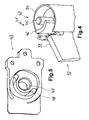
- FIG. 41 An upper hinge 41 is shown in FIG. It's on a door leaf 33 a door leaf holder 34 receiving a door 32.
- the door leaf holder 34 surrounds the upper hinge 41 or the Hinge head 42 in part.
- the hinge head 42 has an upper one Axis section 45 and a projection 46.
- the projection 46 is provided between door leaf 33 and axle section 45. He is there designed in the manner of a circular ring segment.
- the hinge base 43 has an axle receptacle 47 and a backdrop 48 on.
- the expansion of the backdrop 48 results in cooperation with the projection 46, the rotation angle limitation for the door 32 and that upper hinge 41.
- the door can be turned until the protrusion 46 strikes at both ends of the backdrop 48.
- axis section 45 and projection have on the one hand 46 and on the other hand axle holder 47 and backdrop 48 a certain Depth up.
- This is designed such that the hinge head 42 is stationary can be attached to a wall, a frame or the like can.
- the entire door 32 together with the hinge head 42 can be of height a certain area can be moved relative to the hinge base, while the intervention remains.
- hinges 11 and 41 it is possible to have doors 32, for example for shower facilities, also retrospectively on existing frames to install. Since, as can be seen in particular from FIG. 3, for the adjustment of the door can already be installed, the installation or an adjustment is possible easily and very precisely.
Landscapes
- Engineering & Computer Science (AREA)
- Mechanical Engineering (AREA)
- Hinges (AREA)
Abstract
Description
- Fig. 1
- eine Seitenansicht eines unteren Scharniers mit Scharniersockel und Scharnierkopf, welches sowohl eine Höhenjustierung als auch Hebescheiben zur Höhenveränderung aufweist,
- Fig. 2
- das Scharnier aus Fig. 1 in Schrägdarstellung,
- Fig. 3
- eine Schrägdarstellung des Scharniers aus Fig. 1 in einer Scharniersockelfassung mit Höhenjustierschraube,
- Fig. 4
- eine Schrägansicht eines oberen Scharniers mit einem Achsabschnitt sowie einem Vorsprung an einem Scharnierkopf an der Türblatthalterung und
- Fig. 5
- eine Schrägansicht von unten eines oberen Scharniersockels mit Achsaufnahme und Kulisse für die Drehwinkelbegrenzung.
Claims (13)
- Scharniervorrichtung für eine Tür (32), wobei ein oberes Scharnier (41) oben an der Tür und ein unteres Scharnier (11) unten an der Tür vorgesehen sind, gekennzeichnet durch eine Drehwinkelbegrenzung und/oder eine Höhenverstellung bzw. Höhenänderung (18, 21) der Tür, wobei die Scharniervorrichtung für eine Höhenverstellung bei montierter und gewichtsbelasteter Tür (32) ausgebildet ist.
- Scharniervorrichtung nach Anspruch 1, dadurch gekennzeichnet, dass die Höhenverstellung eine Höhenjustierung (21) bei Montage der Tür (32) bzw. der Scharniere (11, 41) umfasst, wobei vorzugsweise die Höhenjustierung nach erfolgter Montage der Tür zugänglich ist, insbesondere ohne notwendige Zugänglichkeit in Achsrichtung.
- Scharniervorrichtung nach Anspruch 1 oder 2, dadurch gekennzeichnet, dass das untere Scharnier (11) einen Scharnierkopf (12) aufweist, der an der Tür (32) befestigbar ist und mit einem unteren Achsabschnitt (17) drehbar an einem Scharniersockel (13) gelagert ist, wobei insbesondere der Scharniersockel höhenjustierbar ist mit der Höhenjustierung (21).
- Scharniervorrichtung nach Anspruch 3, dadurch gekennzeichnet, dass der Scharnierkopf (12) zumindest teilweise drehbar gelagert auf dem Scharniersockel (13) aufliegt, wobei vorzugsweise die Auflage flächig ist.
- Scharniervorrichtung nach Ansprüche 3 oder 4, dadurch gekennzeichnet, dass die Höhenjustierung (21) zwei Schrägen (20) aufweist, die aneinander anliegen, wobei vorzugsweise eine erste Schräge (20a) an der Unterseite des Scharniersockels (13) und eine zweite Schräge (20b) in einem Winkel zu der ersten Schräge dazu längsverschiebbar ausgebildet ist derart, dass sich der Scharniersockel bei Längsverschiebung der zweiten Schräge nach oben oder nach unten bewegt.
- Scharniervorrichtung nach Anspruch 5, dadurch gekennzeichnet, dass der Winkel zwischen 60° und 120° beträgt, vorzugsweise ca. 90°, wobei er insbesondere den Winkel bildet zwischen der Achse der Längsverschiebung der zweiten Schräge (20b) und der Richtung der Höhenbewegung des Scharniersockels (13).
- Scharniervorrichtung nach Anspruch 5 oder 6, dadurch gekennzeichnet, dass mindestens eine der Schrägen (20) eine Fläche ist, vorzugsweise eben, wobei insbesondere beide Schrägen ebene Flächen sind.
- Scharniervorrichtung nach einem der Ansprüche 5 bis 7, dadurch gekennzeichnet, dass die zweite Schräge (20b) längsverschiebbar ist über eine in einem Gewinde (28) gelagerte Höhenjustierschraube (22), die in der der Längsverschiebrichtung der Schräge (20b) entsprechenden Richtung verläuft, wobei vorzugsweise die Höhenjustierschraube (22) separat von der Schräge ausgebildet ist und insbesondere die beiden Schrägen an identischen Teilen (19) vorgesehen sind.
- Scharniervorrichtung nach einem der vorhergehenden Ansprüche, dadurch gekennzeichnet, dass die Höhenverstellung eine Höhenveränderung (18) beim Drehen der Tür (32) aufweist, vorzugsweise durch zwei Schrägen (16) an zwei aneinander anliegenden Teilen (14, 15) eines Scharniers (11), insbesondere am Scharnierkopf (12) und am Scharniersockel (13) des unteren Scharniers (11).
- Scharniervorrichtung nach Anspruch 9, gekennzeichnet durch eine Verstellbarkeit der Lage des Drehwinkelbereichs durch Verdrehen des Scharniersockels (13) mit einer zugehörigen Schräge (16), wobei vorzugsweise der Scharnierkopf (12) über die entsprechende Schräge (16) auf dem Scharniersockel aufliegt.
- Scharniervorrichtung nach Anspruch 9 oder 10, gekennzeichnet durch eine Arretierung der Verstellung der Lage des Drehwinkelbereichs, insbesondere über wenigstens eine an der Außenseite des Scharniersockels (13) angreifende Klemmschraube (23), vorzugsweise auch als Arretierung der Höhenjustierung (21), wobei insbesondere die Klemmschraube in der den Scharniersockel umgebenden Scharnierfassung (26) gelagert ist.
- Scharniervorrichtung nach einem der vorhergehenden Ansprüche, gekennzeichnet durch eine Drehwinkelbegrenzung mit einem Vorsprung (46) nach Art eines Kreisringsegments und einer Kulisse (48) mit einem dem Drehwinkelbereich entsprechenden Kreisringsegmentausschnitt, wobei vorzugsweise der Vorsprung (46) zusammen mit einem Achsabschnitt (45) an einem Scharnierkopf (42) an der Tür (33) ausgebildet ist und die Kulisse (48) mit einer Achsaufnahme (47) an einem entsprechenden Scharniersockel (43) ausgebildet ist.
- Scharniervorrichtung nach Anspruch 12, dadurch gekennzeichnet, dass der Vorsprung (46) und der Achsabschnitt (45) länglich in Richtung der Drehachse ausgebildet sind sowie die Kulisse (48) und die Achsaufnahme (47) eine gewisse Tiefe aufweisen derart, dass sie in Richtung der Drehachse gegeneinander eine gewisse Distanz verschiebbar sind bei Aufrechterhaltung des jeweiligen Eingriffs.
Applications Claiming Priority (2)
| Application Number | Priority Date | Filing Date | Title |
|---|---|---|---|
| DE10205692 | 2002-02-04 | ||
| DE2002105692 DE10205692A1 (de) | 2002-02-04 | 2002-02-04 | Scharniervorrichtung für eine Tür |
Publications (2)
| Publication Number | Publication Date |
|---|---|
| EP1333141A2 true EP1333141A2 (de) | 2003-08-06 |
| EP1333141A3 EP1333141A3 (de) | 2004-11-10 |
Family
ID=7713790
Family Applications (1)
| Application Number | Title | Priority Date | Filing Date |
|---|---|---|---|
| EP03001901A Withdrawn EP1333141A3 (de) | 2002-02-04 | 2003-01-30 | Scharniervorrichtung für eine Tür |
Country Status (2)
| Country | Link |
|---|---|
| EP (1) | EP1333141A3 (de) |
| DE (1) | DE10205692A1 (de) |
Families Citing this family (1)
| Publication number | Priority date | Publication date | Assignee | Title |
|---|---|---|---|---|
| US20240384583A1 (en) * | 2023-05-16 | 2024-11-21 | Kohler Co. | Slow close pivot door |
Family Cites Families (9)
| Publication number | Priority date | Publication date | Assignee | Title |
|---|---|---|---|---|
| DE1249727B (de) * | 1967-09-07 | Vereinigte Baubeschlag-Fabriken Gretsch & Co , GmbH, Leonberg Wurtt) | Beschlag fur Ganzglasturen | |
| US4070728A (en) * | 1976-10-26 | 1978-01-31 | General Electric Company | Vertically adjustable door hinge assembly |
| DE8811473U1 (de) * | 1988-09-10 | 1988-10-27 | Hüppe GmbH & Co, 2903 Bad Zwischenahn | Vorrichtung zum Verstellen der Höhe eines Schwenklagers |
| DE4319422C1 (de) * | 1993-06-11 | 1994-08-04 | Paul Jean Munch | Schwenktüre für Duschkabine |
| DE4440465A1 (de) * | 1994-11-15 | 1996-05-23 | Kienle Gmbh | Beschlag zum Befestigen eines Türflügels, insbesondere eines Türflügels einer Duschabtrennung aus Glas, Kunststoff oder dergleichen |
| DE29623000U1 (de) * | 1996-08-13 | 1997-10-09 | Dorma Gmbh + Co. Kg, 58256 Ennepetal | Band |
| DE20106854U1 (de) * | 2001-04-20 | 2001-10-11 | BGS Briloner Glas- und Sanitärprodukte GmbH, 59929 Brilon | Lager für profillose Türen, insbesondere für Duschkabinen aus mineralischem Glas |
| DE20108224U1 (de) * | 2001-05-16 | 2001-08-02 | Deike, Artur, 28844 Weyhe | Möbel, insbesondere Schrank |
| DE20109669U1 (de) * | 2001-06-12 | 2001-10-25 | Gummi-Stricker GmbH & Co. KG, 48157 Münster | Industrie-Pendeltür mit Gleitkulissen |
-
2002
- 2002-02-04 DE DE2002105692 patent/DE10205692A1/de not_active Withdrawn
-
2003
- 2003-01-30 EP EP03001901A patent/EP1333141A3/de not_active Withdrawn
Also Published As
| Publication number | Publication date |
|---|---|
| DE10205692A1 (de) | 2003-08-07 |
| EP1333141A3 (de) | 2004-11-10 |
Similar Documents
| Publication | Publication Date | Title |
|---|---|---|
| EP2714568B1 (de) | Variierbare kabinentür-schachttür-kupplung | |
| DE9006439U1 (de) | Türband | |
| DE102010047774B4 (de) | Türscharnier | |
| WO2009089882A1 (de) | Einstellbares ecklager für einen flügel eines fensters, einer tür oder dergleichen | |
| DE102010037940A1 (de) | Schiebetür-Rollenführung sowie Anordnung einer Schiebetür-Rollenführung an einem Möbel | |
| DE19924056A1 (de) | Halterung für ein justierbares Gehäuse | |
| DE10205692A1 (de) | Scharniervorrichtung für eine Tür | |
| EP1427894A1 (de) | Abdeckungsanordnung | |
| WO1999046465A1 (de) | Höhenverstellbares gelenkband | |
| DE102004033883B3 (de) | Scharnier für stumpf einschlagende Türen | |
| EP3278693B1 (de) | Beschlag für eine schiebetüre | |
| EP1820927B1 (de) | Buchsenmodul | |
| EP2157266B1 (de) | Scharnier für ein mit einer Tür versehenes Möbelstück | |
| DE3615748C2 (de) | ||
| DE19832025B4 (de) | Höhenverstellbares Gelenkband | |
| DE102013222890B4 (de) | Scharnieranordnung | |
| EP3379013A1 (de) | Justierbare führungsvorrichtung für ein schiebeelement | |
| AT515483B1 (de) | Vorrichtung zur schwenkbaren Anbindung eines plattenartigen Absperrelements an ein feststehendes Bauelement | |
| EP1223275A2 (de) | Band für Türen oder Fenster | |
| DE202004005765U1 (de) | Höhenverstellbares Plattenlager | |
| DE202006010169U1 (de) | Demontagestruktur für einen Stoßdämpfer für Fahrzeuge | |
| DE202007018981U1 (de) | Bodentürschließer | |
| DE10151449A1 (de) | Abdeckungsanordnung | |
| EP4108877A1 (de) | Scharnier für eine türe, ein fenster oder ein ähnliches bauteil | |
| DE102007037471B3 (de) | Klappdeckelvorrichtung für nass gepflegte Böden |
Legal Events
| Date | Code | Title | Description |
|---|---|---|---|
| PUAI | Public reference made under article 153(3) epc to a published international application that has entered the european phase |
Free format text: ORIGINAL CODE: 0009012 |
|
| AK | Designated contracting states |
Designated state(s): AT BE BG CH CY CZ DE DK EE ES FI FR GB GR HU IE IT LI LU MC NL PT SE SI SK TR |
|
| AX | Request for extension of the european patent |
Extension state: AL LT LV MK RO |
|
| PUAL | Search report despatched |
Free format text: ORIGINAL CODE: 0009013 |
|
| AK | Designated contracting states |
Kind code of ref document: A3 Designated state(s): AT BE BG CH CY CZ DE DK EE ES FI FR GB GR HU IE IT LI LU MC NL PT SE SI SK TR |
|
| AX | Request for extension of the european patent |
Extension state: AL LT LV MK RO |
|
| RIC1 | Information provided on ipc code assigned before grant |
Ipc: 7E 05F 1/06 B Ipc: 7E 05D 11/06 B Ipc: 7E 05D 7/08 B Ipc: 7E 05D 7/04 A |
|
| 17P | Request for examination filed |
Effective date: 20050420 |
|
| AKX | Designation fees paid |
Designated state(s): AT BE BG CH CY CZ DE DK EE ES FI FR GB GR HU IE IT LI LU MC NL PT SE SI SK TR |
|
| 17Q | First examination report despatched |
Effective date: 20070524 |
|
| STAA | Information on the status of an ep patent application or granted ep patent |
Free format text: STATUS: THE APPLICATION IS DEEMED TO BE WITHDRAWN |
|
| 18D | Application deemed to be withdrawn |
Effective date: 20070605 |