EP1332798A2 - Spender für flüssige oder pastöse Produkte - Google Patents
Spender für flüssige oder pastöse Produkte Download PDFInfo
- Publication number
- EP1332798A2 EP1332798A2 EP03002285A EP03002285A EP1332798A2 EP 1332798 A2 EP1332798 A2 EP 1332798A2 EP 03002285 A EP03002285 A EP 03002285A EP 03002285 A EP03002285 A EP 03002285A EP 1332798 A2 EP1332798 A2 EP 1332798A2
- Authority
- EP
- European Patent Office
- Prior art keywords
- dispenser
- pump
- valve
- neck
- mandrel
- Prior art date
- Legal status (The legal status is an assumption and is not a legal conclusion. Google has not performed a legal analysis and makes no representation as to the accuracy of the status listed.)
- Granted
Links
Images


Classifications
-
- B—PERFORMING OPERATIONS; TRANSPORTING
- B05—SPRAYING OR ATOMISING IN GENERAL; APPLYING FLUENT MATERIALS TO SURFACES, IN GENERAL
- B05B—SPRAYING APPARATUS; ATOMISING APPARATUS; NOZZLES
- B05B11/00—Single-unit hand-held apparatus in which flow of contents is produced by the muscular force of the operator at the moment of use
- B05B11/0005—Components or details
- B05B11/0062—Outlet valves actuated by the pressure of the fluid to be sprayed
- B05B11/007—Outlet valves actuated by the pressure of the fluid to be sprayed being opened by deformation of a sealing element made of resiliently deformable material, e.g. flaps, skirts, duck-bill valves
-
- B—PERFORMING OPERATIONS; TRANSPORTING
- B05—SPRAYING OR ATOMISING IN GENERAL; APPLYING FLUENT MATERIALS TO SURFACES, IN GENERAL
- B05B—SPRAYING APPARATUS; ATOMISING APPARATUS; NOZZLES
- B05B11/00—Single-unit hand-held apparatus in which flow of contents is produced by the muscular force of the operator at the moment of use
- B05B11/01—Single-unit hand-held apparatus in which flow of contents is produced by the muscular force of the operator at the moment of use characterised by the means producing the flow
- B05B11/10—Pump arrangements for transferring the contents from the container to a pump chamber by a sucking effect and forcing the contents out through the dispensing nozzle
- B05B11/1028—Pumps having a pumping chamber with a deformable wall
-
- B—PERFORMING OPERATIONS; TRANSPORTING
- B05—SPRAYING OR ATOMISING IN GENERAL; APPLYING FLUENT MATERIALS TO SURFACES, IN GENERAL
- B05B—SPRAYING APPARATUS; ATOMISING APPARATUS; NOZZLES
- B05B11/00—Single-unit hand-held apparatus in which flow of contents is produced by the muscular force of the operator at the moment of use
- B05B11/01—Single-unit hand-held apparatus in which flow of contents is produced by the muscular force of the operator at the moment of use characterised by the means producing the flow
- B05B11/10—Pump arrangements for transferring the contents from the container to a pump chamber by a sucking effect and forcing the contents out through the dispensing nozzle
- B05B11/1042—Components or details
- B05B11/1066—Pump inlet valves
- B05B11/1067—Pump inlet valves actuated by pressure
- B05B11/1069—Pump inlet valves actuated by pressure the valve being made of a resiliently deformable material or being urged in a closed position by a spring
Definitions
- the invention relates to a dispenser for dispensing metered amounts of liquid to pasty products, consisting of a cylindrical storage container open at the bottom, its lower open end by an axially displaceable Piston is closed, and one arranged on the storage container Dispenser head, which is a bell-shaped dispenser pump with elastic side walls contains that together with an inlet valve and one in the pump neck arranged outlet valve forms a closed pump chamber.
- a dispenser of the type described above is from EP 0 048 420 B1 known.
- the dispenser consists of a hollow cylindrical storage container with a lower open end, which by an axially displaceable Replenishment piston is closed.
- the top of the storage container has a top surface with an inlet valve.
- a dispenser head is arranged with one located in the dispenser head Dispenser pump, the pump chamber on the input and output side Check valves is limited and with a downstream of the dispenser pump Mouthpiece with application opening.
- dispensers train the type mentioned with a headpiece, the dispenser pump with an outlet valve with the simplest possible design and installation Valve flap is equipped.
- the bell-shaped dispenser pump as a one-piece construction element of the dispenser head, which is inserted into the dispenser head from below and in the assembled state (on the storage container is the dispenser head attached) together with the top surface of the storage tank Pump chamber forms, is at its upper end to a neck with circular Cross section narrowed.
- This inside hollow neck of the dispenser pump represents the Outlet opening of the pump chamber and is by arranging a valve flap used on its upper end as an exhaust valve.
- valve flap integrally the entire upper passage opening of the Pump neck covered so that it can work as an outlet valve.
- the valve flap is this exhaust valve has a rubber disc with a central bore, which are attached to a protruding axial mandrel of the pump neck is.
- the mandrel is part of the dispenser pump or of the pump neck and is made in one piece with it, with it over webs is connected to the pump neck.
- the mandrel is this with a circumferential groove at the level of the upper edge of the Pump neck formed, in which the rubber disc engages when plugged in.
- the pump neck is closed with a neck that closes the neck at the top Cap made in one piece.
- this cap By separating this cap then only partially separated from the pump neck so that the cap over one remaining undivided area in the form of a tab with the pump neck stays connected. Because the tab is made of the same elastic material as the entire dispenser pump is made, the tab now acts as one Hinge for the valve flap, the original cap of the pump neck
- valve flap is thus reduced to a simple partial Separation process on the one-piece manufactured by, for example, injection molding Dispenser pump.
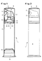
- Figures 1 and 2 is in a vertical section (Fig. 1) and in a front view (Fig. 2) a dispenser 1 for dispensing metered amounts of liquid to pasty Products shown with a dispenser pump 10 designed according to the invention.
- the dispenser 1 consists of a storage container 3 with a lower open one End 31 for filling the product to be donated. After filling this open end 31 is then closed by a piston 32.
- the upper end of the storage container 3 is through a top surface 30 limited with inlet valve 7.
- the dispenser head 2 is pushed onto the storage container 3, consisting of from the bell-shaped or dome-like dispenser pump 10 with an outlet valve 8 and with a dispensing channel 6 arranged downstream of the outlet valve 8, Mouthpiece 4 with application opening and closure flap 5.
- the dispenser head 2 is pushed onto the storage container 3 so that the bottom open Dispenser pump 10 sits tightly on the top surface of the storage container 3 or is locked with this and between the dispenser pump 10 and Cover surface 30 forms a pump chamber 18.
- the dispenser head 2 is too whose protection a cap 9 is pushed on.
- valve flap 20 is, for example formed by a rubber washer with a central hole 26 on a central mandrel 11 of the pump neck 12 is pushed on.
- the dispenser pump 10 of Figure 1 is shown again enlarged.
- the upper area of the pump neck 12 are in the through opening present here 15, for example, four webs 16 arranged in one piece with the common mandrel 11 are formed.
- the mandrel 11 has the level of Upper edge 27 pump neck 12 a circumferential groove 14.
- the valve flap or here a rubber disc 20 with its central hole 26 pushed on, where it snaps into the groove 14 and seals on the upper edge 27 rests and thus the entire upper through opening 15 of the Pump neck 12 covered.
- FIG. 4 shows a further embodiment of an exhaust valve 8 according to the invention shown.
- the pump neck 12 With otherwise the same design of the dispenser pump 10 is at this alternative embodiment, only the pump neck 12 changed. Under Elimination of the webs 16 and the mandrel 11 is the upper end of the pump neck 12 smooth and formed with a pivotable valve flap or cap 20 '.
- the pump neck 12 and the cap 20 ' were made in one piece and then partially separated by a separation process until the cap 20 ' only over a small undivided area, a tab 22 with the Pump neck 12 is movably connected.
- the movable cap 20 'or Valve flap thus represents a particularly simple embodiment of a valve flap represents the functionally reliable pump neck 12 or the passage opening 15 'seals and opens.
- FIG. 5 and 6 is a dispenser head in an enlarged partial section 2 of a dispenser 1 with a dispenser pump 10, the outlet valve thereof 8 according to FIG. 4 not with a flat but with a dome-like valve flap 20 "is formed, which is manufactured together with the pump neck 12 has been.
- valve flap 33 of the inlet valve 7 is one with a central hole formed elastic disc 33, preferably one Rubber washer, which is attached to a protruding mandrel 34 of the top surface 30 is after which the protruding head of the mandrel 34 (over the disc 33) has been deformed by thermal deformation at its end, that the disc 33 is now permanently attached to this mandrel 34
- FIGS. 5 and 6 10 The fastening of the dispenser pump is also more clearly shown in FIGS. 5 and 6 10 with its side walls 13 by means of a latching connection 37 in an annular Groove 36 of the storage container 3 can be removed.
- the annular groove 36 is made from a container extension 35 extending beyond the top surface 30 and the side edge 38 of the top surface 30 into which the lower edge of the Side walls 13 are inserted and locked by means of a locking connection.
Landscapes
- Closures For Containers (AREA)
- Containers And Packaging Bodies Having A Special Means To Remove Contents (AREA)
- Jellies, Jams, And Syrups (AREA)
Abstract
Description
- Fig. 1
- einen Spender in einem Vertikalschnitt,
- Fig. 2
- den Spender der Figur 1 in einer Vorderansicht,
- Fig. 3
- einen vergrößerten Teilausschnitt der Spenderpumpe in einem Vertikalschnitt,
- Fig. 4
- einen vergrößerten Teilausschnitt einer weiteren Ausführungsform der Spenderpumpe in einem Vertikalschnitt,
- Fig. 5
- einen vergrößerten Teilausschnitt eines Spenders mit geöffnetem Auslassventil,
- Fig. 6
- einen vergrößerten Teilausschnitt eines Spenders mit geschlossenem Auslassventil gemäß Fig. 5.
- 1
- Spender
- 2
- Spenderkopf
- 3
- Speicherbehälter
- 4
- Mundstück
- 5
- Verschlusslasche
- 6
- Spendekanal
- 7
- Einlassventil
- 8
- Auslassventil
- 9
- Kappe
- 10
- glockenförmige Spenderpumpe (Dom)
- 11
- Dorn
- 12
- Pumpenhals
- 13
- elastische Seitenwände des Doms
- 14
- Nut im Dorn
- 15, 15', 15"
- Durchgangsöffnung
- 16
- Stege
- 17
- Ausstömrichtung
- 18
- Pumpkammer
- 20, 20', 20"
- obere Ventilklappe
- 22
- Lasche
- 24
- Druckrichtung
- 26
- Loch in Gummischeibe
- 27
- Oberkante Pumpenhals
- 30
- Deckfläche
- 31
- offenes Ende des Speicherbehälters 3
- 32
- Kolben
- 33
- untere Ventilklappe (Gummi)
- 34
- Nietkopf
- 35
- Behälterverlängerung
- 36
- ringförmige Nut
- 37
- Rastverbindung
- 38
- Seitenrand der Deckfläche
- 39
- Rastverbindung
Claims (9)
- Spender (1) zur Abgabe dosierter Mengen flüssiger bis pastöser Produkte, bestehend aus einem unten offenen zylindrischen Speicherbehälter (3), dessen unteres offene Ende (31) durch einen axial verschiebbaren Kolben (32) verschlossen ist, und einem auf dem Speicherbehälter (3) angeordneten Spenderkopf (2), der eine glockenförmige Spenderpumpe (10) mit elastischen Seitenwänden (13) enthält, die gemeinsam mit einem Einlassventil (7) und einem im Pumpenhals (12) angeordneten Auslassventil (8) eine geschlossene Pumpkammer (18) ausbildet, dadurch gekennzeichnet, dass das Auslassventil (8) als Teil des Pumpenhalses (12) mit diesem so einstückig gefertigt ist, dass durch einen einfachen Arbeitsschritt die gesamte obere Durchgangsöffnung (15, 15', 15") des Pumpenhalses (12) mit einer Ventilklappe (20, 20', 20") verschließbar ist.
- Spender (1) nach Anspruch 1, dadurch gekennzeichnet, dass das Auslassventil (8) mit einer Ventilklappe (20), vorzugsweise aus Gummi mit einem zentralen Loch (26) ausgebildet ist, die auf einen vorstehenden axialen Dorn (11) des Pumpenhalses (12) aufgesteckt ist.
- Spender (1) nach Anspruch 2, dadurch gekennzeichnet, dass der Dorn (11) ein Teil des Pumpenhalses (12) ist und mit diesem einstückig gefertigt und über Stege (16) verbunden ist.
- Spender (1) nach Anspruch 3, dadurch gekennzeichnet, dass der Dorn (11) mit einer umlaufenden Nut (14) in Höhe der Oberkante (27) des Pumpenhalses (12) zum Einrasten der Ventilklappe (20) auf dem Dorn (11) ausgebildet ist.
- Spender (1) nach Anspruch 1, dadurch gekennzeichnet, dass das Auslassventil (8) als einstückige Ventilklappe (20', 20") ausgebildet und Teil des Pumpenhalses (12) ist.
- Spender (1) nach Anspruch 5, dadurch gekennzeichnet, dass die Ventilklappe (20', 20") als geschlossene Kappe den oberen Abschluss des Pumpenhalses (12) bildet mit diesem zunächst einstückig gefertigt und dann durch einen Trennvorgang teilweise vom Pumpenhals (12) so abtrennbar ausgebildet ist, dass die Ventilkappe (20', 20") über einen verbleibenden ungetrennten Bereich in Form einer Lasche (22) mit dem Pumpenhals (12) verbunden bleibt.
- Spender (1) nach einem der Ansprüche 1 bis 6, dadurch gekennzeichnet, dass die Seitenwände (13) der Spenderpumpe (10) mit ihren unteren Enden in einer ringförmigen Nut (36) verrastet sind, die aus der Behälterverlängerung (35) und dem Seitenrand (38) der Deckfläche (30) gebildet ist.
- Spender (1) nach einem der Ansprüche 1 bis 7, dadurch gekennzeichnet, dass die Ventilklappe (33) des Einlassventils (7) eine mit einem zentralen Loch ausgebildete elastische Scheibe ist, vorzugsweise eine Gummischeibe, die auf einen vorstehenden Dorn (34) der Deckfläche (30) aufgesteckt ist.
- Spender (1) nach Anspruch 8, dadurch gekennzeichnet, dass die elastische Scheibe (33) nach ihrem Aufstecken auf den Dorn (34) durch eine nietförmige thermische Verformung des Dorns (34) unlösbar auf diesem befestigt ist.
Applications Claiming Priority (2)
| Application Number | Priority Date | Filing Date | Title |
|---|---|---|---|
| DE20201742U | 2002-02-05 | ||
| DE20201742U DE20201742U1 (de) | 2002-02-05 | 2002-02-05 | Spender für fließfähige Produkte |
Publications (3)
| Publication Number | Publication Date |
|---|---|
| EP1332798A2 true EP1332798A2 (de) | 2003-08-06 |
| EP1332798A3 EP1332798A3 (de) | 2003-08-20 |
| EP1332798B1 EP1332798B1 (de) | 2007-09-19 |
Family
ID=7967399
Family Applications (1)
| Application Number | Title | Priority Date | Filing Date |
|---|---|---|---|
| EP03002285A Expired - Lifetime EP1332798B1 (de) | 2002-02-05 | 2003-02-03 | Spender für flüssige oder pastöse Produkte |
Country Status (4)
| Country | Link |
|---|---|
| US (1) | US7028865B2 (de) |
| EP (1) | EP1332798B1 (de) |
| AT (1) | ATE373521T1 (de) |
| DE (2) | DE20201742U1 (de) |
Cited By (1)
| Publication number | Priority date | Publication date | Assignee | Title |
|---|---|---|---|---|
| WO2018014929A1 (de) * | 2016-07-18 | 2018-01-25 | Rpc Bramlage Gmbh | Spender für flüssige bis pastöse massen |
Families Citing this family (19)
| Publication number | Priority date | Publication date | Assignee | Title |
|---|---|---|---|---|
| US7367476B2 (en) | 2004-08-30 | 2008-05-06 | Rieke Corporation | Airless dispensing pump with tamper evidence features |
| US7654418B2 (en) * | 2004-08-30 | 2010-02-02 | Rieke Corporation | Airless dispensing pump |
| FR2900643B1 (fr) * | 2006-05-05 | 2008-10-10 | Airlessystems Soc Par Actions | Organe de distribution de produit fluide et distributeur comprenant un tel organe de distribution |
| DE602006004849D1 (de) * | 2006-05-15 | 2009-03-05 | Wintek Sarl | Spender für fliessfähige Produkte mit einer Druckkolbenpumpe und einer Membrane |
| KR100856326B1 (ko) * | 2006-07-19 | 2008-09-03 | 삼성전기주식회사 | 레이저 리프트 오프를 이용한 유전체 박막을 갖는 박막 커패시터 내장된 인쇄회로기판 제조방법, 및 이로부터 제조된 박막 커패시터 내장된 인쇄회로기판 |
| DE102008029004A1 (de) * | 2007-06-29 | 2009-01-02 | Rpc Bramlage Gmbh | Spender zur Ausgabe flüssiger oder pastöser Massen |
| IT1399593B1 (it) * | 2010-04-14 | 2013-04-26 | Guala Dispensing Spa | Erogatore a grilletto per liquidi con valvola di aspirazione. |
| IT1399592B1 (it) * | 2010-04-14 | 2013-04-26 | Guala Dispensing Spa | Erogatore a grilletto per liquidi con fermo per la valvola di mandata. |
| WO2013023129A1 (en) * | 2011-08-11 | 2013-02-14 | Soneco Llc | Securing product storage tanks against unauthorized delivery |
| US10278487B2 (en) | 2014-05-07 | 2019-05-07 | Colgate-Palmolive Company | Oral care implements and methods of manufacturing the same |
| KR101501027B1 (ko) * | 2014-06-16 | 2015-03-12 | (주)연우 | 캡슐 토출용 펌프 용기 |
| FR3041409A1 (fr) * | 2015-09-22 | 2017-03-24 | Cep Tubes | Valve anti-retour etanche |
| GB201518910D0 (en) * | 2015-10-26 | 2015-12-09 | Rieke Packaging Systems Ltd | Dispensers |
| FR3048192B1 (fr) * | 2016-02-25 | 2020-10-23 | Albea Lacrost | Pompe pour receptacle, notamment un flacon de produit cosmetique, et dispositif de distribution comprenant une telle pompe |
| US11154887B2 (en) * | 2017-12-20 | 2021-10-26 | Sulzer Mixpac Ag | Piston, cartridge and method of venting a cartridge |
| US12070768B2 (en) | 2017-12-20 | 2024-08-27 | Medmix Switzerland Ag | Piston, cartridge and method of venting a cartridge |
| CN111731667A (zh) * | 2020-07-07 | 2020-10-02 | 上海升村包装材料有限公司 | 一种环保型喷泵 |
| FR3098797B1 (fr) * | 2019-07-19 | 2022-01-28 | Promens Sa | Dispositif de bouchage d’un contenant d’un produit liquide à pâteux et recharge fermée par un tel dispositif |
| CN114521185B (zh) * | 2019-07-23 | 2024-08-06 | 里克包装系统有限公司 | 具有内部塞件密封的全聚合物泵分配器 |
Family Cites Families (19)
| Publication number | Priority date | Publication date | Assignee | Title |
|---|---|---|---|---|
| AT61990B (de) | 1911-12-11 | 1913-11-10 | Emil Merten | Mitnehmerklinken-Schaltwerk für Kettenrädergetriebe. |
| DE2611644A1 (de) * | 1976-03-19 | 1977-09-29 | Henkel & Cie Gmbh | Behaelter fuer kosmetika |
| DE3035742A1 (de) * | 1980-09-22 | 1982-05-13 | Henkel KGaA, 4000 Düsseldorf | Klappenventil |
| DE3035728A1 (de) * | 1980-09-22 | 1982-05-06 | Henkel KGaA, 4000 Düsseldorf | Spender |
| DE3035705A1 (de) * | 1980-09-22 | 1982-05-06 | Henkel KGaA, 4000 Düsseldorf | Spender |
| EP0084638B1 (de) * | 1982-01-19 | 1987-12-23 | Gap Gesellschaft Für Auswertungen Und Patente Ag | Spender für pastöse Produkte |
| US4535820A (en) * | 1984-05-24 | 1985-08-20 | Burron Medical Inc. | Normally closed check valve |
| DE3725650A1 (de) | 1987-08-03 | 1989-02-23 | Fehrer Gummihaar | Herstellung einer verbindung zwischen einem aus geschaeumtem kunststoff bestehenden teil und einem anbauelement |
| FR2621014B1 (fr) * | 1987-09-25 | 1989-11-24 | Cebal | Distributeur de produit pateux a fonctionnement ameliore et element de pompage correspondant |
| DE3738548A1 (de) * | 1987-11-13 | 1989-05-24 | Bramlage Gmbh | Spender fuer pastoese massen |
| US4936493A (en) * | 1987-11-23 | 1990-06-26 | Calmar, Inc. | Elastomeric valve and piston structure for product dispenser |
| DE4307752A1 (de) * | 1993-03-11 | 1994-09-15 | Coster Tecnologie Speciali Spa | Vorrichtung zum dosierten Austrag eines fließfähigen Mediums aus einem Behälter |
| DE4430583A1 (de) | 1994-08-18 | 1996-02-22 | Harald Dipl Ing Loesche | Zahnpasta-Spender mit Pumpe |
| US5544789A (en) | 1995-01-05 | 1996-08-13 | Calmar Inc. | Bellows pump dispenser |
| FR2731690B1 (fr) * | 1995-03-17 | 1997-06-06 | Total Raffinage Distribution | Dispositif de limitation de perte de liquide, adaptable sur un organe de distribution de liquide sous pression |
| JP3527324B2 (ja) | 1995-07-13 | 2004-05-17 | 株式会社吉野工業所 | クリーム状物注出容器 |
| DE29712144U1 (de) * | 1997-07-10 | 1997-09-25 | Wiegner, Georg, Kowloon, Hong Kong | Pumpe zum dosierten Austragen von flüssigen, gelartigen oder viskosen Substanzen |
| DE19729516C2 (de) * | 1997-07-10 | 1999-04-22 | Georg Wiegner | Pumpe zum dosierten Austragen von flüssigen, gelartigen oder viskosen Substanzen |
| JP2000117162A (ja) | 1998-10-14 | 2000-04-25 | Akira Matsumoto | 簡易型ポンプディスペンサー |
-
2002
- 2002-02-05 DE DE20201742U patent/DE20201742U1/de not_active Expired - Lifetime
-
2003
- 2003-01-29 US US10/353,822 patent/US7028865B2/en not_active Expired - Fee Related
- 2003-02-03 DE DE50308202T patent/DE50308202D1/de not_active Expired - Lifetime
- 2003-02-03 AT AT03002285T patent/ATE373521T1/de not_active IP Right Cessation
- 2003-02-03 EP EP03002285A patent/EP1332798B1/de not_active Expired - Lifetime
Cited By (4)
| Publication number | Priority date | Publication date | Assignee | Title |
|---|---|---|---|---|
| WO2018014929A1 (de) * | 2016-07-18 | 2018-01-25 | Rpc Bramlage Gmbh | Spender für flüssige bis pastöse massen |
| CN109862969A (zh) * | 2016-07-18 | 2019-06-07 | Rpc布兰姆拉格股份有限公司 | 用于液态至膏状物料的供送器 |
| US10618069B2 (en) | 2016-07-18 | 2020-04-14 | Rpc Bramlage Gmbh | Dispenser for liquid to pasty compositions |
| CN109862969B (zh) * | 2016-07-18 | 2021-09-21 | Rpc布兰姆拉格股份有限公司 | 用于液态至膏状物料的供送器 |
Also Published As
| Publication number | Publication date |
|---|---|
| US7028865B2 (en) | 2006-04-18 |
| DE20201742U1 (de) | 2003-03-20 |
| EP1332798B1 (de) | 2007-09-19 |
| US20030168475A1 (en) | 2003-09-11 |
| DE50308202D1 (de) | 2007-10-31 |
| EP1332798A3 (de) | 2003-08-20 |
| ATE373521T1 (de) | 2007-10-15 |
Similar Documents
| Publication | Publication Date | Title |
|---|---|---|
| EP1332798A2 (de) | Spender für flüssige oder pastöse Produkte | |
| EP0112351B1 (de) | Spender für pastöse produkte | |
| DE69522549T2 (de) | Vorrichtung zur abgabe von steriler flüssigkeit | |
| EP0738543B1 (de) | Abgabepumpe aus Kunststoff für pastenartige Stoffe | |
| DE3586780T2 (de) | Pumpe zur verteilung einer fluessigkeit aus einem behaelter. | |
| DE69720504T2 (de) | Abgabevorrichtung für ein zweikomponentiges fluid | |
| DE69110344T2 (de) | Sprüh- und Dosiervorrichtung. | |
| DE69206215T2 (de) | Schutzkappe und Wischer für die Auslassöffnung von Spendern. | |
| DE3033392A1 (de) | Vorrichtung zur ausgabe von pasteusen oder breiigen medien | |
| DE2645089A1 (de) | Betaetigungsvorrichtung fuer einen ausgabemechanismus fuer fluessige, halbfluessige oder gasfoermige substanzen | |
| DE2640575B2 (de) | Membranpumpe | |
| DE69821495T2 (de) | Handpumpe mit durch Plastikfedern beaufschlagtem Freikolben | |
| DE69200485T3 (de) | Spender für fliessfähige Medien. | |
| EP2499950A2 (de) | Pumpeinrichtung für ein Behältnis für flüssige, pastöse oder aufschäumbare Hautreinigungs- und Pflegepräparate | |
| DE2640837A1 (de) | Manuell betaetigbare pumpe | |
| EP0250965A1 (de) | Spender | |
| DE69910417T2 (de) | Spender mit ringförmiger ausgabe | |
| DE3828811A1 (de) | Dosier- und spraypumpe fuer fluessige und niederviskose stoffe | |
| DE602004009551T2 (de) | Abgabevorrichtung mit einer druckbetätigbaren pumpe | |
| EP1694564B1 (de) | Spenderpumpe | |
| DE3235171A1 (de) | Spender, insbesondere fuer pastoeses gut | |
| DE3909633A1 (de) | Dosierpumpe | |
| DE69209788T2 (de) | Pumpe zur Förderung von einem flüssigen oder pastösen Produkt, und Ausgabebehälter mit einer solchen Pumpe | |
| EP3736049B1 (de) | Austragkopf und flüssigkeitsspender mit einem austragkopf | |
| EP1871539A1 (de) | Spender zur ausgabe flüssiger bis pastöser massen |
Legal Events
| Date | Code | Title | Description |
|---|---|---|---|
| PUAI | Public reference made under article 153(3) epc to a published international application that has entered the european phase |
Free format text: ORIGINAL CODE: 0009012 |
|
| PUAL | Search report despatched |
Free format text: ORIGINAL CODE: 0009013 |
|
| AK | Designated contracting states |
Designated state(s): AT BE BG CH CY CZ DE DK EE ES FI FR GB GR HU IE IT LI LU MC NL PT SE SI SK TR |
|
| AX | Request for extension of the european patent |
Extension state: AL LT LV MK RO |
|
| AK | Designated contracting states |
Designated state(s): AT BE BG CH CY CZ DE DK EE ES FI FR GB GR HU IE IT LI LU MC NL PT SE SI SK TR |
|
| AX | Request for extension of the european patent |
Extension state: AL LT LV MK RO |
|
| 17P | Request for examination filed |
Effective date: 20031209 |
|
| AKX | Designation fees paid |
Designated state(s): AT BE BG CH CY CZ DE DK EE ES FI FR GB GR HU IE IT LI LU MC NL PT SE SI SK TR |
|
| 17Q | First examination report despatched |
Effective date: 20041215 |
|
| 17Q | First examination report despatched |
Effective date: 20041215 |
|
| GRAP | Despatch of communication of intention to grant a patent |
Free format text: ORIGINAL CODE: EPIDOSNIGR1 |
|
| GRAS | Grant fee paid |
Free format text: ORIGINAL CODE: EPIDOSNIGR3 |
|
| GRAA | (expected) grant |
Free format text: ORIGINAL CODE: 0009210 |
|
| AK | Designated contracting states |
Kind code of ref document: B1 Designated state(s): AT BE BG CH CY CZ DE DK EE ES FI FR GB GR HU IE IT LI LU MC NL PT SE SI SK TR |
|
| REG | Reference to a national code |
Ref country code: GB Ref legal event code: FG4D Free format text: NOT ENGLISH |
|
| GBT | Gb: translation of ep patent filed (gb section 77(6)(a)/1977) |
Effective date: 20070919 |
|
| REG | Reference to a national code |
Ref country code: CH Ref legal event code: EP |
|
| REF | Corresponds to: |
Ref document number: 50308202 Country of ref document: DE Date of ref document: 20071031 Kind code of ref document: P |
|
| REG | Reference to a national code |
Ref country code: IE Ref legal event code: FG4D Free format text: LANGUAGE OF EP DOCUMENT: GERMAN |
|
| PG25 | Lapsed in a contracting state [announced via postgrant information from national office to epo] |
Ref country code: FI Free format text: LAPSE BECAUSE OF FAILURE TO SUBMIT A TRANSLATION OF THE DESCRIPTION OR TO PAY THE FEE WITHIN THE PRESCRIBED TIME-LIMIT Effective date: 20070919 |
|
| NLV1 | Nl: lapsed or annulled due to failure to fulfill the requirements of art. 29p and 29m of the patents act | ||
| RAP2 | Party data changed (patent owner data changed or rights of a patent transferred) |
Owner name: RPC WIKO GMBH |
|
| PG25 | Lapsed in a contracting state [announced via postgrant information from national office to epo] |
Ref country code: ES Free format text: LAPSE BECAUSE OF FAILURE TO SUBMIT A TRANSLATION OF THE DESCRIPTION OR TO PAY THE FEE WITHIN THE PRESCRIBED TIME-LIMIT Effective date: 20071230 Ref country code: GR Free format text: LAPSE BECAUSE OF FAILURE TO SUBMIT A TRANSLATION OF THE DESCRIPTION OR TO PAY THE FEE WITHIN THE PRESCRIBED TIME-LIMIT Effective date: 20071220 Ref country code: NL Free format text: LAPSE BECAUSE OF FAILURE TO SUBMIT A TRANSLATION OF THE DESCRIPTION OR TO PAY THE FEE WITHIN THE PRESCRIBED TIME-LIMIT Effective date: 20070919 |
|
| REG | Reference to a national code |
Ref country code: IE Ref legal event code: FD4D |
|
| ET | Fr: translation filed | ||
| PG25 | Lapsed in a contracting state [announced via postgrant information from national office to epo] |
Ref country code: SK Free format text: LAPSE BECAUSE OF FAILURE TO SUBMIT A TRANSLATION OF THE DESCRIPTION OR TO PAY THE FEE WITHIN THE PRESCRIBED TIME-LIMIT Effective date: 20070919 Ref country code: PT Free format text: LAPSE BECAUSE OF FAILURE TO SUBMIT A TRANSLATION OF THE DESCRIPTION OR TO PAY THE FEE WITHIN THE PRESCRIBED TIME-LIMIT Effective date: 20080219 Ref country code: CZ Free format text: LAPSE BECAUSE OF FAILURE TO SUBMIT A TRANSLATION OF THE DESCRIPTION OR TO PAY THE FEE WITHIN THE PRESCRIBED TIME-LIMIT Effective date: 20070919 |
|
| PG25 | Lapsed in a contracting state [announced via postgrant information from national office to epo] |
Ref country code: SE Free format text: LAPSE BECAUSE OF FAILURE TO SUBMIT A TRANSLATION OF THE DESCRIPTION OR TO PAY THE FEE WITHIN THE PRESCRIBED TIME-LIMIT Effective date: 20071219 |
|
| PLBE | No opposition filed within time limit |
Free format text: ORIGINAL CODE: 0009261 |
|
| STAA | Information on the status of an ep patent application or granted ep patent |
Free format text: STATUS: NO OPPOSITION FILED WITHIN TIME LIMIT |
|
| PG25 | Lapsed in a contracting state [announced via postgrant information from national office to epo] |
Ref country code: DK Free format text: LAPSE BECAUSE OF FAILURE TO SUBMIT A TRANSLATION OF THE DESCRIPTION OR TO PAY THE FEE WITHIN THE PRESCRIBED TIME-LIMIT Effective date: 20070919 |
|
| 26N | No opposition filed |
Effective date: 20080620 |
|
| BERE | Be: lapsed |
Owner name: RPC WIKO G.M.B.H. & CO. KG Effective date: 20080228 |
|
| REG | Reference to a national code |
Ref country code: CH Ref legal event code: PL |
|
| PG25 | Lapsed in a contracting state [announced via postgrant information from national office to epo] |
Ref country code: CH Free format text: LAPSE BECAUSE OF NON-PAYMENT OF DUE FEES Effective date: 20080229 Ref country code: LI Free format text: LAPSE BECAUSE OF NON-PAYMENT OF DUE FEES Effective date: 20080229 Ref country code: IE Free format text: LAPSE BECAUSE OF FAILURE TO SUBMIT A TRANSLATION OF THE DESCRIPTION OR TO PAY THE FEE WITHIN THE PRESCRIBED TIME-LIMIT Effective date: 20070919 Ref country code: MC Free format text: LAPSE BECAUSE OF NON-PAYMENT OF DUE FEES Effective date: 20080228 |
|
| PG25 | Lapsed in a contracting state [announced via postgrant information from national office to epo] |
Ref country code: EE Free format text: LAPSE BECAUSE OF FAILURE TO SUBMIT A TRANSLATION OF THE DESCRIPTION OR TO PAY THE FEE WITHIN THE PRESCRIBED TIME-LIMIT Effective date: 20070919 |
|
| PG25 | Lapsed in a contracting state [announced via postgrant information from national office to epo] |
Ref country code: BE Free format text: LAPSE BECAUSE OF NON-PAYMENT OF DUE FEES Effective date: 20080228 |
|
| PG25 | Lapsed in a contracting state [announced via postgrant information from national office to epo] |
Ref country code: AT Free format text: LAPSE BECAUSE OF NON-PAYMENT OF DUE FEES Effective date: 20080203 |
|
| PG25 | Lapsed in a contracting state [announced via postgrant information from national office to epo] |
Ref country code: SI Free format text: LAPSE BECAUSE OF FAILURE TO SUBMIT A TRANSLATION OF THE DESCRIPTION OR TO PAY THE FEE WITHIN THE PRESCRIBED TIME-LIMIT Effective date: 20070919 |
|
| PG25 | Lapsed in a contracting state [announced via postgrant information from national office to epo] |
Ref country code: CY Free format text: LAPSE BECAUSE OF FAILURE TO SUBMIT A TRANSLATION OF THE DESCRIPTION OR TO PAY THE FEE WITHIN THE PRESCRIBED TIME-LIMIT Effective date: 20070919 |
|
| PG25 | Lapsed in a contracting state [announced via postgrant information from national office to epo] |
Ref country code: BG Free format text: LAPSE BECAUSE OF FAILURE TO SUBMIT A TRANSLATION OF THE DESCRIPTION OR TO PAY THE FEE WITHIN THE PRESCRIBED TIME-LIMIT Effective date: 20071219 |
|
| PGFP | Annual fee paid to national office [announced via postgrant information from national office to epo] |
Ref country code: FR Payment date: 20100315 Year of fee payment: 8 |
|
| PGFP | Annual fee paid to national office [announced via postgrant information from national office to epo] |
Ref country code: DE Payment date: 20100108 Year of fee payment: 8 Ref country code: GB Payment date: 20100219 Year of fee payment: 8 |
|
| PG25 | Lapsed in a contracting state [announced via postgrant information from national office to epo] |
Ref country code: LU Free format text: LAPSE BECAUSE OF NON-PAYMENT OF DUE FEES Effective date: 20080203 Ref country code: HU Free format text: LAPSE BECAUSE OF FAILURE TO SUBMIT A TRANSLATION OF THE DESCRIPTION OR TO PAY THE FEE WITHIN THE PRESCRIBED TIME-LIMIT Effective date: 20080320 |
|
| PG25 | Lapsed in a contracting state [announced via postgrant information from national office to epo] |
Ref country code: TR Free format text: LAPSE BECAUSE OF FAILURE TO SUBMIT A TRANSLATION OF THE DESCRIPTION OR TO PAY THE FEE WITHIN THE PRESCRIBED TIME-LIMIT Effective date: 20070919 |
|
| PG25 | Lapsed in a contracting state [announced via postgrant information from national office to epo] |
Ref country code: IT Free format text: LAPSE BECAUSE OF NON-PAYMENT OF DUE FEES Effective date: 20080229 |
|
| GBPC | Gb: european patent ceased through non-payment of renewal fee |
Effective date: 20110203 |
|
| REG | Reference to a national code |
Ref country code: FR Ref legal event code: ST Effective date: 20111102 |
|
| REG | Reference to a national code |
Ref country code: DE Ref legal event code: R119 Ref document number: 50308202 Country of ref document: DE Effective date: 20110901 |
|
| PG25 | Lapsed in a contracting state [announced via postgrant information from national office to epo] |
Ref country code: FR Free format text: LAPSE BECAUSE OF NON-PAYMENT OF DUE FEES Effective date: 20110228 |
|
| PG25 | Lapsed in a contracting state [announced via postgrant information from national office to epo] |
Ref country code: GB Free format text: LAPSE BECAUSE OF NON-PAYMENT OF DUE FEES Effective date: 20110203 |
|
| PG25 | Lapsed in a contracting state [announced via postgrant information from national office to epo] |
Ref country code: DE Free format text: LAPSE BECAUSE OF NON-PAYMENT OF DUE FEES Effective date: 20110901 |