EP1329643A2 - Parkbremse für Kraftfahrzeuge - Google Patents
Parkbremse für Kraftfahrzeuge Download PDFInfo
- Publication number
- EP1329643A2 EP1329643A2 EP03000841A EP03000841A EP1329643A2 EP 1329643 A2 EP1329643 A2 EP 1329643A2 EP 03000841 A EP03000841 A EP 03000841A EP 03000841 A EP03000841 A EP 03000841A EP 1329643 A2 EP1329643 A2 EP 1329643A2
- Authority
- EP
- European Patent Office
- Prior art keywords
- piston
- bolt
- brake
- radial groove
- snap ring
- Prior art date
- Legal status (The legal status is an assumption and is not a legal conclusion. Google has not performed a legal analysis and makes no representation as to the accuracy of the status listed.)
- Granted
Links
Images
Classifications
-
- F—MECHANICAL ENGINEERING; LIGHTING; HEATING; WEAPONS; BLASTING
- F16—ENGINEERING ELEMENTS AND UNITS; GENERAL MEASURES FOR PRODUCING AND MAINTAINING EFFECTIVE FUNCTIONING OF MACHINES OR INSTALLATIONS; THERMAL INSULATION IN GENERAL
- F16D—COUPLINGS FOR TRANSMITTING ROTATION; CLUTCHES; BRAKES
- F16D55/00—Brakes with substantially-radial braking surfaces pressed together in axial direction, e.g. disc brakes
- F16D55/24—Brakes with substantially-radial braking surfaces pressed together in axial direction, e.g. disc brakes with a plurality of axially-movable discs, lamellae, or pads, pressed from one side towards an axially-located member
- F16D55/26—Brakes with substantially-radial braking surfaces pressed together in axial direction, e.g. disc brakes with a plurality of axially-movable discs, lamellae, or pads, pressed from one side towards an axially-located member without self-tightening action
- F16D55/36—Brakes with a plurality of rotating discs all lying side by side
-
- F—MECHANICAL ENGINEERING; LIGHTING; HEATING; WEAPONS; BLASTING
- F16—ENGINEERING ELEMENTS AND UNITS; GENERAL MEASURES FOR PRODUCING AND MAINTAINING EFFECTIVE FUNCTIONING OF MACHINES OR INSTALLATIONS; THERMAL INSULATION IN GENERAL
- F16D—COUPLINGS FOR TRANSMITTING ROTATION; CLUTCHES; BRAKES
- F16D2121/00—Type of actuator operation force
- F16D2121/02—Fluid pressure
-
- F—MECHANICAL ENGINEERING; LIGHTING; HEATING; WEAPONS; BLASTING
- F16—ENGINEERING ELEMENTS AND UNITS; GENERAL MEASURES FOR PRODUCING AND MAINTAINING EFFECTIVE FUNCTIONING OF MACHINES OR INSTALLATIONS; THERMAL INSULATION IN GENERAL
- F16D—COUPLINGS FOR TRANSMITTING ROTATION; CLUTCHES; BRAKES
- F16D2121/00—Type of actuator operation force
- F16D2121/02—Fluid pressure
- F16D2121/12—Fluid pressure for releasing a normally applied brake, the type of actuator being irrelevant or not provided for in groups F16D2121/04 - F16D2121/10
-
- F—MECHANICAL ENGINEERING; LIGHTING; HEATING; WEAPONS; BLASTING
- F16—ENGINEERING ELEMENTS AND UNITS; GENERAL MEASURES FOR PRODUCING AND MAINTAINING EFFECTIVE FUNCTIONING OF MACHINES OR INSTALLATIONS; THERMAL INSULATION IN GENERAL
- F16D—COUPLINGS FOR TRANSMITTING ROTATION; CLUTCHES; BRAKES
- F16D2123/00—Multiple operation forces
Definitions
- the invention relates to a parking brake for motor vehicles with the features of the preamble of claim 1 and method for mounting a parking brake for motor vehicles with the features of the preambles of claims 2 and 3.
- Parking brakes for motor vehicles are known Spring force to close and by means of hydraulic pressure are to solve.
- Such parking brakes for motor vehicles have at least one brake plate on an axle beam in one Brake housing on and springs that hold the brake plates be squeezed together.
- a piston releases the brake plates against the force of the springs when a piston chamber with hydraulic Pressure is applied.
- At least one hole in the Piston with one pin each is provided, the pin the spring force is hydraulically sealed by the piston chamber limiting disc transfers to the brake discs.
- the Bolt is with a cylindrical section in the bore held by the piston.
- the bolt is with a Screw thread in the hole designed as a blind hole of the piston.
- Advantageous at this level Technology is that the radial offset of the holes for the Bolt in the washer balanced when screwing the bolt can be. It is disadvantageous that screws can loosen and the piston chamber then leaks, so that can no longer be guaranteed that the parking brake can be solved.
- a parking brake for motor vehicles is known from EP 0 913 304 A2 known in which the bolts in the cylindrical section in the bore of the piston and at the free end of the cylindrical section each have a radial groove.
- the bolt is fastened in the piston in the radial groove cylindrical section in the bore an O-ring and in the radial groove at the free end of the cylindrical section a circlip is used.
- a disadvantage of this stand the technology is that precise manufacturing tolerances between Washer, bolt and piston are required.
- the object of the invention is to provide a parking brake To create motor vehicles that have the disadvantages of the state the technology does not have and advantageous methods for Specify installation of such a parking brake.
- a parking brake for motor vehicles has at least one brake plate on an axle body in a brake housing and springs with which the brake plates are pressed together.
- a piston releases the brake discs against the force of the springs when hydraulic pressure is applied to a piston chamber.
- a disc delimits the piston chamber hydraulically tight and at least one bore in the piston is provided, each with a bolt which is held with a cylindrical section in the bore of the piston, the bolt having a radial groove in the bore of the piston.
- the bore in the piston is designed as a blind bore with a radial groove, and a snap ring is provided which can be mounted in the radial grooves of the cylindrical section of the bolt and the bore in the piston.
- a snap ring is provided which can be mounted in the radial grooves of the cylindrical section of the bolt and the bore in the piston.
- the assembly of a parking brake for motor vehicles so that the snap ring in the radial groove of the cylindrical portion of the bolt inserted and the pin with the snap ring into the hole is inserted until the snap ring into the radial groove the hole in the piston snaps into place.
- the assembly of a parking brake for motor vehicles also take place so that the snap ring in the radial groove of the bore is inserted in the piston, and the bolt is inserted into the hole until the snap ring in the radial groove of the cylindrical portion of the Bolt snaps in.
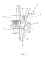
- a parking brake 1 for motor vehicles has brake plates 2 on a rotatable gear part or rotatable axle body 3 in a fixed housing 4 and springs 5 in a fixed housing 6, with which the brake plates 2 are pressed together.
- a guided in the housing 6 Piston 7 acts on pin 8 and one in the fixed Housing 4 held pressure transmission element 9 the Brake discs 2 against the force of the springs 5 when a piston chamber 10 closed with a closure 11 Line 12 is pressurized with hydraulic pressure.
- a Disc 13 delimits the piston chamber 10 hydraulically tight.
- Bolts 8 are hydraulically sealed by the disk 13 guided.
- Bolt 8, piston 7 and washer 13 are each on Provide circumference with sealing rings 14. Disc 13 is in contact a stop 15 in the housing 6.
- a blind bore 16 in the piston 7 is provided with each a bolt 8 which with a cylindrical portion 17 in the blind bore 16 of the piston 7 and a section 18th is held hydraulically tight in the disc 13, the Bolt 8 in the cylindrical section 17 has a radial groove 19 having.
- the blind bore 16 in the piston 7 has a corresponding one radial groove 20 formed.
- a snap ring 21 is provided which in the radial grooves 19, 20 of the cylindrical Section 17 of the bolt 8 and the blind hole 16 can be mounted in the piston 7.
- the snap ring 21 is in the radial Groove 19 of the cylindrical portion 17 of the bolt 8 is inserted is, and the bolt 8 with the snap ring 21 in the Blind bore 16 inserted until the snap ring 21 into the radial Groove 20 of the blind bore 16 snaps into the piston 7.
- the assembly is done so that the snap ring 21 in the radial groove 20 of the blind bore 16 is inserted in the piston 7 is, and the bolt 8 is inserted into the blind bore 16 until the snap ring 21 in the radial groove 19 of the cylindrical portion 17 of the bolt 8 snaps.
Landscapes
- Engineering & Computer Science (AREA)
- General Engineering & Computer Science (AREA)
- Mechanical Engineering (AREA)
- Braking Arrangements (AREA)
Abstract
- mindestens einer Bremslamelle (2) auf einem Achskörper (3) in einem Bremsgehäuse (4),
- Federn (5), mit denen die Bremslamellen (2) zusammengedrückt werden,
- einem Kolben (7), der die Bremslamellen (2) gegen die Kraft der Federn (5) löst, wenn ein Kolbenraum (10) mit Druck beaufschlagt wird,
- mit mindestens einer Bohrung (16) im Kolben (7) mit je einem Bolzen (8), der mit einem zylindrischen Abschnitt (17) in der Bohrung (16) des Kolbens (7) gehalten ist, wobei der Bolzen (8) im zylindrischen Abschnitt (17) in der Bohrung (16) des Kolbens (7) eine radiale Nut (19) aufweist,
Description
Gemäß der Erfindung weist eine Parkbremse für Kraftfahrzeuge mindestens eine Bremslamelle auf einem Achskörper in einem Bremsgehäuse auf und Federn, mit denen die Bremslamellen zusammengedrückt werden. Ein Kolben löst die Bremslamellen gegen die Kraft der Federn, wenn ein Kolbenraum mit hydraulischem Druck beaufschlagt wird. Eine Scheibe begrenzt den Kolbenraum hydraulisch dicht und mindestens eine Bohrung im Kolben ist vorgesehen mit je einem Bolzen, der mit einem zylindrischen Abschnitt in der Bohrung des Kolbens gehalten ist, wobei der Bolzen im zylindrischen Abschnitt in der Bohrung des Kolbens eine radiale Nut aufweist. Gemäß der Erfindung ist die Bohrung im Kolben als Sackbohrung mit einer radialen Nut ausgebildet ist, und ein Sprengring ist vorgesehen, der in die radialen Nuten des zylindrischen Abschnitts des Bolzens und der Bohrung im Kolben montiert werden kann. Vorteilhafterweise ergibt sich bei der erfindungsgemäßen Parkbremse für Kraftfahrzeuge, daß auf grund der Sackbohrung Undichtigkeiten ausgeschlossen sind. Radiales Spiel zwischen Bolzen und Kolbenbohrung ist zulässig, so daß sich besondere Anforderungen an die Fertigungstoleranzen erübrigen.
Es zeigen:
- Fig. 1
- eine Teil-Ansicht einer Parkbremse für Kraftfahrzeuge gemäß der Erfindung;
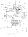
- Fig. 2
- eine Teil-Ansicht einer Bremsanordnung mit Betriebs- und Feststellbremse.
- 1
- Parkbremse
- 2
- Bremslamelle
- 3
- Achskörper
- 4
- Gehäuse
- 5
- Federn
- 6
- Gehäuse
- 7
- Kolben
- 8
- Bolzen
- 9
- Druckübertragungselement
- 10
- Kolbenraum
- 11
- Verschluß
- 12
- Leitung
- 13
- Scheibe
- 14
- Dichtringe
- 15
- Anschlag
- 16
- Sackbohrung
- 17
- Zylindrischer Abschnitt
- 18
- Bolzenabschnitt
- 19
- Radiale Nut
- 20
- Radiale Nut
- 21
- Sprengring
- 22
- Bolzenabschnitt
- 23
- Leitung
- 24
- Kolben
- 25
- Feder
Claims (3)
- Parkbremse (1) für Kraftfahrzeuge mitdadurch gekennzeichnet, daß die Bohrung (16) im Kolben (7) als Sackbohrung mit einer radialen Nut (20) ausgebildet ist, und ein Sprengring (21) vorgesehen ist, der in die radialen Nuten (19, 20) des zylindrischen Abschnitts (17) des Bolzens (8) und der Sackbohrung (16) im Kolben (7) montiert werden kann.mindestens einer Bremslamelle (2) auf einem Achskörper (3) in einem Bremsgehäuse (4),Federn (5), mit denen die Bremslamellen (2) zusammengedrückt werden,einem Kolben (7), der die Bremslamellen (2) gegen die Kraft der Federn (5) löst, wenn ein Kolbenraum (10) mit Druck beaufschlagt wird,mit mindestens einer Bohrung (16) im Kolben (7) mit je einem Bolzen (8), der mit einem zylindrischen Abschnitt (17) in der Bohrung (16) des Kolbens (7) gehalten ist, wobei der Bolzen (8) im zylindrischen Abschnitt (17) in der Bohrung (16) des Kolbens (7) eine radiale Nut (19) aufweist,
- Verfahren zur Montage einer Parkbremse (1) für Kraftfahrzeuge gemäß Anspruch 1, dadurch gekennzeichnet, daß der Sprengring (21) in die radiale Nut (19) des zylindrischen Abschnitts (17) des Bolzens (8) eingesetzt wird, und der Bolzen (8) mit dem Sprengring (21) in die Sackbohrung (16) eingeführt wird bis der Sprengring (21) in die radiale Nut (20) der Sackbohrung (16) im Kolben (7) einschnappt.
- Verfahren zur Montage einer Parkbremse (1) für Kraftfahrzeuge gemäß Anspruch 1, dadurch gekennzeichnet, daß der Sprengring (21) in die radiale Nut (20) der Sackbohrung (16) im Kolben (7) eingesetzt wird, und der Bolzen (8) in die Sackbohrung (16) eingeführt wird bis der Sprengring (21) in die radiale Nut (19) des zylindrischen Abschnitts (17) des Bolzens (8) einschnappt.
Applications Claiming Priority (2)
| Application Number | Priority Date | Filing Date | Title |
|---|---|---|---|
| DE2002101366 DE10201366A1 (de) | 2002-01-16 | 2002-01-16 | Parkbremse für Kraftfahrzeuge |
| DE10201366 | 2002-01-16 |
Publications (3)
| Publication Number | Publication Date |
|---|---|
| EP1329643A2 true EP1329643A2 (de) | 2003-07-23 |
| EP1329643A3 EP1329643A3 (de) | 2005-04-27 |
| EP1329643B1 EP1329643B1 (de) | 2006-07-05 |
Family
ID=7712225
Family Applications (1)
| Application Number | Title | Priority Date | Filing Date |
|---|---|---|---|
| EP20030000841 Expired - Lifetime EP1329643B1 (de) | 2002-01-16 | 2003-01-15 | Parkbremse für Kraftfahrzeuge |
Country Status (2)
| Country | Link |
|---|---|
| EP (1) | EP1329643B1 (de) |
| DE (2) | DE10201366A1 (de) |
Cited By (1)
| Publication number | Priority date | Publication date | Assignee | Title |
|---|---|---|---|---|
| WO2009059720A1 (en) * | 2007-11-08 | 2009-05-14 | Agco Gmbh | Brake for utility vehicle |
Families Citing this family (3)
| Publication number | Priority date | Publication date | Assignee | Title |
|---|---|---|---|---|
| DE102006001893B4 (de) * | 2006-01-14 | 2023-05-11 | Zf Friedrichshafen Ag | Parkbremse für ein Kraftfahrzeug |
| DE102006001895B4 (de) * | 2006-01-14 | 2021-07-01 | Zf Friedrichshafen Ag | Parkbremse für ein Kraftfahrzeug |
| GB2575076B (en) * | 2018-06-28 | 2021-10-20 | Bamford Excavators Ltd | An actuation mechanism for a multi-plate brake |
Family Cites Families (8)
| Publication number | Priority date | Publication date | Assignee | Title |
|---|---|---|---|---|
| DE3026131A1 (de) * | 1980-07-10 | 1982-02-18 | Alfred Teves Gmbh, 6000 Frankfurt | Betaetigungsvorrichtung fuer scheibenbremsen |
| DE3635118A1 (de) * | 1986-10-15 | 1988-04-21 | Rexroth Mannesmann Gmbh | Hydraulisch gelueftete lamellenbremse mit gerigem luftdruck |
| DE19504451B4 (de) * | 1995-02-10 | 2006-09-14 | Bosch Rexroth Aktiengesellschaft | Antriebseinrichtung für mobile Arbeitsgeräte |
| DE19642022B4 (de) * | 1996-07-05 | 2009-07-02 | Linde Material Handling Gmbh | Axialkolbenmaschine in Schrägscheibenbauweise, insbesondere Radmotor |
| IT1296239B1 (it) * | 1997-10-22 | 1999-06-18 | Carraro Spa | Gruppo integrato per la frenatura di stazionamento e di servizio di organi rotanti. |
| DE19754491A1 (de) * | 1997-12-09 | 1999-06-17 | Stromag Ag | Federdruckbremse |
| DE19755156A1 (de) * | 1997-12-11 | 1999-06-17 | Mannesmann Rexroth Ag | Radialkolbenmotor mit Reibschlußbremse |
| DE10030282C2 (de) * | 2000-06-20 | 2003-09-25 | Sauer Danfoss Holding As Nordb | Hydraulik-Antriebsanordnung |
-
2002
- 2002-01-16 DE DE2002101366 patent/DE10201366A1/de not_active Withdrawn
-
2003
- 2003-01-15 DE DE50304103T patent/DE50304103D1/de not_active Expired - Fee Related
- 2003-01-15 EP EP20030000841 patent/EP1329643B1/de not_active Expired - Lifetime
Cited By (2)
| Publication number | Priority date | Publication date | Assignee | Title |
|---|---|---|---|---|
| WO2009059720A1 (en) * | 2007-11-08 | 2009-05-14 | Agco Gmbh | Brake for utility vehicle |
| US7980365B2 (en) | 2007-11-08 | 2011-07-19 | Agco Gmbh | Brake for a utility vehicle |
Also Published As
| Publication number | Publication date |
|---|---|
| DE10201366A1 (de) | 2003-07-24 |
| EP1329643A3 (de) | 2005-04-27 |
| DE50304103D1 (de) | 2006-08-17 |
| EP1329643B1 (de) | 2006-07-05 |
Similar Documents
| Publication | Publication Date | Title |
|---|---|---|
| DE2840300C2 (de) | ||
| DE10353695A1 (de) | Elektrische Scheibenbremse | |
| EP1062402A2 (de) | Seilfensterheberantrieb | |
| DE69103010T2 (de) | Fahrzeugbremse mit einem bremszylinderbohrlocheinsatzstück. | |
| EP1819935A2 (de) | Bremssattel einer scheibenbremse | |
| WO2007025494A1 (de) | Hydraulische kupplung mit bajonettverschluss und drahtformfeder zur verdrehsicherung | |
| EP1329643B1 (de) | Parkbremse für Kraftfahrzeuge | |
| DE3803079A1 (de) | Elektromechanisch betaetigbarer druckmodulator fuer blockierschutz- und antriebsschlupfregelanlagen | |
| DE19861380A1 (de) | Scheibenbremse | |
| DE102014005680A1 (de) | Montagewerkzeugset | |
| DE102019118708A1 (de) | Druckversorgungseinrichtung mit einer Zahnradpumpe | |
| DE10008606B4 (de) | Kraftübertragungsmechanismus mit einem Sprengring zu dessen Montage | |
| DE10331129B4 (de) | Auswuchtmaschine mit einer Spanneinrichtung | |
| DE3708699A1 (de) | Befestigungsanordnung fuer einen bremsbelag zur sicherung des belages gegen radiale verschiebung | |
| DE19754491A1 (de) | Federdruckbremse | |
| DE102006001893B4 (de) | Parkbremse für ein Kraftfahrzeug | |
| EP1634048B1 (de) | Drucksensor-anordnung | |
| DE102006001895A1 (de) | Parkbremse für ein Kraftfahrzeug | |
| DE102007001210B3 (de) | Scheibenbremse eines Nutzfahrzeugs | |
| DE102010026728A1 (de) | Bremsscheibe und Montageverfahren | |
| DE3125087A1 (de) | "bremse fuer einen hydraulischen motor" | |
| EP1785636A2 (de) | Schraubensicherung | |
| DE4305631C2 (de) | Druckmittelgesteuerter Antrieb | |
| DE102019118697A1 (de) | Zahnradpumpe | |
| DE4100903C2 (de) |
Legal Events
| Date | Code | Title | Description |
|---|---|---|---|
| PUAI | Public reference made under article 153(3) epc to a published international application that has entered the european phase |
Free format text: ORIGINAL CODE: 0009012 |
|
| AK | Designated contracting states |
Designated state(s): AT BE BG CH CY CZ DE DK EE ES FI FR GB GR HU IE IT LI LU MC NL PT SE SI SK TR |
|
| AX | Request for extension of the european patent |
Extension state: AL LT LV MK RO |
|
| PUAL | Search report despatched |
Free format text: ORIGINAL CODE: 0009013 |
|
| AK | Designated contracting states |
Kind code of ref document: A3 Designated state(s): AT BE BG CH CY CZ DE DK EE ES FI FR GB GR HU IE IT LI LU MC NL PT SE SI SK TR |
|
| AX | Request for extension of the european patent |
Extension state: AL LT LV MK RO |
|
| RIC1 | Information provided on ipc code assigned before grant |
Ipc: 7B 60T 17/08 B Ipc: 7F 16D 55/40 A Ipc: 7F 16D 65/14 B |
|
| 17P | Request for examination filed |
Effective date: 20050719 |
|
| AKX | Designation fees paid |
Designated state(s): DE FR GB IT |
|
| GRAP | Despatch of communication of intention to grant a patent |
Free format text: ORIGINAL CODE: EPIDOSNIGR1 |
|
| GRAS | Grant fee paid |
Free format text: ORIGINAL CODE: EPIDOSNIGR3 |
|
| GRAA | (expected) grant |
Free format text: ORIGINAL CODE: 0009210 |
|
| AK | Designated contracting states |
Kind code of ref document: B1 Designated state(s): DE FR GB IT |
|
| PG25 | Lapsed in a contracting state [announced via postgrant information from national office to epo] |
Ref country code: IT Free format text: LAPSE BECAUSE OF FAILURE TO SUBMIT A TRANSLATION OF THE DESCRIPTION OR TO PAY THE FEE WITHIN THE PRESCRIBED TIME-LIMIT;WARNING: LAPSES OF ITALIAN PATENTS WITH EFFECTIVE DATE BEFORE 2007 MAY HAVE OCCURRED AT ANY TIME BEFORE 2007. THE CORRECT EFFECTIVE DATE MAY BE DIFFERENT FROM THE ONE RECORDED. Effective date: 20060705 |
|
| REG | Reference to a national code |
Ref country code: GB Ref legal event code: FG4D Free format text: NOT ENGLISH |
|
| REF | Corresponds to: |
Ref document number: 50304103 Country of ref document: DE Date of ref document: 20060817 Kind code of ref document: P |
|
| GBT | Gb: translation of ep patent filed (gb section 77(6)(a)/1977) |
Effective date: 20060911 |
|
| ET | Fr: translation filed | ||
| PLBE | No opposition filed within time limit |
Free format text: ORIGINAL CODE: 0009261 |
|
| STAA | Information on the status of an ep patent application or granted ep patent |
Free format text: STATUS: NO OPPOSITION FILED WITHIN TIME LIMIT |
|
| 26N | No opposition filed |
Effective date: 20070410 |
|
| PG25 | Lapsed in a contracting state [announced via postgrant information from national office to epo] |
Ref country code: DE Free format text: LAPSE BECAUSE OF NON-PAYMENT OF DUE FEES Effective date: 20070801 |
|
| GBPC | Gb: european patent ceased through non-payment of renewal fee |
Effective date: 20070115 |
|
| REG | Reference to a national code |
Ref country code: FR Ref legal event code: ST Effective date: 20070930 |
|
| PG25 | Lapsed in a contracting state [announced via postgrant information from national office to epo] |
Ref country code: GB Free format text: LAPSE BECAUSE OF NON-PAYMENT OF DUE FEES Effective date: 20070115 |
|
| PG25 | Lapsed in a contracting state [announced via postgrant information from national office to epo] |
Ref country code: FR Free format text: LAPSE BECAUSE OF NON-PAYMENT OF DUE FEES Effective date: 20070131 |