EP1329427A2 - Vorrichtung und Verfahren zur Entwässerung von Schlämmen - Google Patents
Vorrichtung und Verfahren zur Entwässerung von Schlämmen Download PDFInfo
- Publication number
- EP1329427A2 EP1329427A2 EP03001150A EP03001150A EP1329427A2 EP 1329427 A2 EP1329427 A2 EP 1329427A2 EP 03001150 A EP03001150 A EP 03001150A EP 03001150 A EP03001150 A EP 03001150A EP 1329427 A2 EP1329427 A2 EP 1329427A2
- Authority
- EP
- European Patent Office
- Prior art keywords
- sludge
- box
- pressure
- belt
- press plate
- Prior art date
- Legal status (The legal status is an assumption and is not a legal conclusion. Google has not performed a legal analysis and makes no representation as to the accuracy of the status listed.)
- Withdrawn
Links
- 239000010802 sludge Substances 0.000 title claims abstract description 63
- 238000000034 method Methods 0.000 title claims abstract description 14
- 239000000203 mixture Substances 0.000 claims abstract description 15
- XLYOFNOQVPJJNP-UHFFFAOYSA-N water Substances O XLYOFNOQVPJJNP-UHFFFAOYSA-N 0.000 claims abstract description 13
- 239000000654 additive Substances 0.000 claims description 42
- 230000000996 additive effect Effects 0.000 claims description 31
- 238000002156 mixing Methods 0.000 claims description 17
- 239000008187 granular material Substances 0.000 claims description 12
- 230000005484 gravity Effects 0.000 claims description 7
- 238000012544 monitoring process Methods 0.000 claims description 6
- 239000010801 sewage sludge Substances 0.000 claims description 6
- 230000005540 biological transmission Effects 0.000 claims description 5
- 238000011049 filling Methods 0.000 claims description 5
- 239000007788 liquid Substances 0.000 claims description 5
- 239000010902 straw Substances 0.000 claims description 5
- 230000001360 synchronised effect Effects 0.000 claims description 3
- 239000000126 substance Substances 0.000 claims description 2
- 239000002002 slurry Substances 0.000 abstract 5
- 238000007873 sieving Methods 0.000 abstract 1
- 238000001035 drying Methods 0.000 description 8
- 239000007787 solid Substances 0.000 description 5
- 230000008901 benefit Effects 0.000 description 4
- 239000000463 material Substances 0.000 description 4
- 238000011144 upstream manufacturing Methods 0.000 description 3
- 230000000694 effects Effects 0.000 description 2
- 238000005265 energy consumption Methods 0.000 description 2
- 239000000706 filtrate Substances 0.000 description 2
- 238000000227 grinding Methods 0.000 description 2
- 230000002028 premature Effects 0.000 description 2
- 230000003068 static effect Effects 0.000 description 2
- 241001417527 Pempheridae Species 0.000 description 1
- 239000011358 absorbing material Substances 0.000 description 1
- 230000009286 beneficial effect Effects 0.000 description 1
- 239000006227 byproduct Substances 0.000 description 1
- 230000003247 decreasing effect Effects 0.000 description 1
- 230000001419 dependent effect Effects 0.000 description 1
- 238000011161 development Methods 0.000 description 1
- 238000011038 discontinuous diafiltration by volume reduction Methods 0.000 description 1
- 238000011068 loading method Methods 0.000 description 1
- 238000012423 maintenance Methods 0.000 description 1
- 238000012806 monitoring device Methods 0.000 description 1
- 238000012545 processing Methods 0.000 description 1
- 239000000047 product Substances 0.000 description 1
- 238000012546 transfer Methods 0.000 description 1
Images


Classifications
-
- C—CHEMISTRY; METALLURGY
- C02—TREATMENT OF WATER, WASTE WATER, SEWAGE, OR SLUDGE
- C02F—TREATMENT OF WATER, WASTE WATER, SEWAGE, OR SLUDGE
- C02F11/00—Treatment of sludge; Devices therefor
- C02F11/12—Treatment of sludge; Devices therefor by de-watering, drying or thickening
- C02F11/121—Treatment of sludge; Devices therefor by de-watering, drying or thickening by mechanical de-watering
- C02F11/123—Treatment of sludge; Devices therefor by de-watering, drying or thickening by mechanical de-watering using belt or band filters
-
- B—PERFORMING OPERATIONS; TRANSPORTING
- B01—PHYSICAL OR CHEMICAL PROCESSES OR APPARATUS IN GENERAL
- B01D—SEPARATION
- B01D29/00—Filters with filtering elements stationary during filtration, e.g. pressure or suction filters, not covered by groups B01D24/00 - B01D27/00; Filtering elements therefor
- B01D29/09—Filters with filtering elements stationary during filtration, e.g. pressure or suction filters, not covered by groups B01D24/00 - B01D27/00; Filtering elements therefor with filtering bands, e.g. movable between filtering operations
-
- B—PERFORMING OPERATIONS; TRANSPORTING
- B01—PHYSICAL OR CHEMICAL PROCESSES OR APPARATUS IN GENERAL
- B01D—SEPARATION
- B01D29/00—Filters with filtering elements stationary during filtration, e.g. pressure or suction filters, not covered by groups B01D24/00 - B01D27/00; Filtering elements therefor
- B01D29/50—Filters with filtering elements stationary during filtration, e.g. pressure or suction filters, not covered by groups B01D24/00 - B01D27/00; Filtering elements therefor with multiple filtering elements, characterised by their mutual disposition
- B01D29/56—Filters with filtering elements stationary during filtration, e.g. pressure or suction filters, not covered by groups B01D24/00 - B01D27/00; Filtering elements therefor with multiple filtering elements, characterised by their mutual disposition in series connection
-
- B—PERFORMING OPERATIONS; TRANSPORTING
- B01—PHYSICAL OR CHEMICAL PROCESSES OR APPARATUS IN GENERAL
- B01D—SEPARATION
- B01D29/00—Filters with filtering elements stationary during filtration, e.g. pressure or suction filters, not covered by groups B01D24/00 - B01D27/00; Filtering elements therefor
- B01D29/76—Handling the filter cake in the filter for purposes other than for regenerating
- B01D29/80—Handling the filter cake in the filter for purposes other than for regenerating for drying
- B01D29/82—Handling the filter cake in the filter for purposes other than for regenerating for drying by compression
- B01D29/824—Handling the filter cake in the filter for purposes other than for regenerating for drying by compression using pistons
Definitions
- the invention relates to a device and a Process for dewatering sludge and sludge-containing Mixtures such as sewage sludge, industrial sludge and others sludge-like starting products, in which the liquid Share of the sludge to be dewatered through a sieve belt is pressed and the remaining mud press cake is transported away.
- a belt filter press is known from DE 196 27 884 A1, that works with two sieve belts. On the one belt the sludge to be drained is brought in and thereby already dewatered on a slope. The second The sieve belt is then applied to the sludge from above brought so that the sludge between the two sieve belts is composed and thus around several deflecting and pressing rollers can be directed and transported between which he is with increasing contact pressure is pressed, i.e. dewatered.
- This press consists of a large number of individual parts, such as rollers, rolls, bearings, two sieve belts and others more that are aligned and in their movement must be coordinated; e.g.
- the sludge is between two endless filter tapes held by carrying tapes, guided continuously through high-pressure stations via rollers, in which by means of a number of hydraulic cylinders a circumferential tank band with increasing pressure is pressed against the mud chamber.
- a circumferential tank band with increasing pressure is pressed against the mud chamber.
- the object of the invention is a device for drainage of sludges and sludge-like mixtures to create that with structurally comparatively simple means and low energy consumption a higher degree of drainage is achieved than with previously used devices.
- the new device is said to be without constant monitoring Require trouble-free operation during operation and be as maintenance-free as possible.
- the pre-drainage station and the pressure drainage station are the same as the device compared to known ones Makes systems cheaper and space-saving.
- a moisture sensor can be beneficial a signal to the pressure device or cylinder-piston unit surrender if after reaching a certain Degree of pre-drainage with pressure drainage to start; depending on the signal of the Moisture sensor or a liquid meter in the press water department, preferably in cycles, the pressure be increased to its maximum. Through this slow and moisture-dependent increase in pressure becomes a too high flow rate and a premature Blockage of the filter belt avoided.
- Stops are advantageously provided in the box, against which the press plate strikes during its lifting movement and takes the box in its further lifting movement and takes off from the sieve belt.
- the sieve belt is preferably in the form of an endless belt Roles performed, of which at least one as a drive role is designed for the movement of the sieve belt. It can on one roll a preferably the entire width of the Sieve belt covering stripper can be provided. If after the pressure drainage of the box from the sieve belt is lifted, the sieve belt is driven and the remaining mud press cakes from the dewatering station transported out and stripped. The circulating Sieve belt can then be used with water if necessary provided nozzles are cleaned until it is ready for the next Drainage is stopped again.
- the sieve belt is separated by an intermediate support frame arranged on the rollers and so always is kept level and horizontal. This can be done through a perforated plate or slotted screen between the support structure and the sieve belt still be supported.
- the Synchronism is controlled by a synchronous control.
- the balance beam can be in its pivot point with a car to be firmly connected by means of rollers in a guide frame attached to a fixed frame Movable up and down in the opposite direction to the press plate is.
- the balance beam is deflected by the actuator provided thereon first Actuated switch via which the hydraulic pressure (or the inflow of pressure medium) in the cylinder-piston units is controllable; with a further deflection of the The balance beam then becomes a monitoring or emergency switch actuated, via which the system is switched off and / or a The fault is displayed.
- a shutdown of the plant only takes place if the balance on the balance beam is above the hydraulic pressure (or inflow) in the cylinder-piston unit cannot be restored; unnecessary standstill is avoided.
- the switches on the carriage can be on either side of the balance beam attached actuator can be arranged.
- the box has a circular cross section and the press plate is therefore also circular, improved the statics and it can preferably be done with a single, central pressure device (cylinder-piston unit) reached a higher pressure to pressurize the press plate become.
- cylinder-piston unit central pressure device
- a rail is arranged in which the whole Crushing roller covering the width of the belt can be moved is.
- a mixing container with an agitator for mixing a coarsely crushed, drainage-promoting additive upstream of the sludge to be dewatered.
- the sludge to be dewatered is fed through a sludge line introduced into the mixing container, and this Sludge pipe is also with a branch pipe an additive container connected from which the additive added before mixing in the flocculant becomes.
- the additive can be metered in by means of a conveying device, for example a screw conveyor, arranged between the branch connector and the additive container.
- the additive preferably consists of a mixture of smaller press cake parts or granules accumulating after the pressure dewatering of the sludge from the remaining sludge press cake or granulate and a moisture-absorbing material of large surface area and light weight, such as sawdust or crocheted straw.
- the proportion of the additive in the mud press cake should preferably not be too large.
- the quantity ratio saves weight and, at the same time, the drainage is promoted in such a way that an equally good or even better result is achieved with less pressure than in known devices (about 1 -5 bar instead of 15 bar), thus also saving energy.
- the granules can be removed directly from the press cake, which has only been roughly crushed and leaves the dewatering station after the pressure drainage.
- the degree of dryness of the press cake achieved with the device according to the invention makes a special drying cycle superfluous.
- the grinding of the press cake is also superfluous and would even be disadvantageous, since the drainage effect of a coarsely comminuted additive, for example cubed, is significantly better than that of a finely ground additive.
- the press cake usually disintegrates into pieces of a suitable size when it leaves the dewatering station.
- an agitator in the mixing tank preferably with a floor scraper intended.
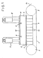
- FIG. 1 shows, partly in section, the side view of a first embodiment of the device according to the invention for dewatering sludge.
- An endless screen belt 1 is placed over two rollers 2 and 3 and can of at least one or both of the rollers 2, 3 are driven.
- a lifting and lowering box 4 is arranged above the sieve belt 1, the lowered state with a seal 5 rests on the screen belt 1 and through openings 8 with the draining sludge can be filled.
- the sieve belt 1 is by a support structure 6 and a perforated plate or slotted sieve 7 held in an almost flat position.
- box 4 is one by means of pressure devices, preferably hydraulic Cylinder-piston units 9, lifting and lowering press plate 10 arranged during this movement on the inner wall of the box 4 sealed by a sliding seal 11 slides along.
- the box 4 is lowered into the sieve belt 1 Condition and with the press plate 10 raised by the Openings 8 filled with mud, and it is done first pre-dewatering of the sludge solely by gravity; the filtrate water is drained off via a line 12.
- a reduction in the volume of the water to be drained can already be achieved Sludge can be achieved by over 50%.
- the Press plate 10 After the end of this first drainage phase, the Press plate 10 through the cylinder-piston units 9, or another suitable printing device, e.g. a spindle, pressed down in box 4. Even before the press plate 10 comes into direct contact with the mud the pressure drainage phase by doing that in box 4 existing air cushion pushes water out of the mud.
- the Pressure drainage phase continues when the press plate 10 reached the mud and slowly, but preferably in cycles, increasing to a maximum Pressure drained.
- the beginning of pressure drainage and the Pressure increases can depend on a moisture sensor (not shown in the drawing) controlled become.
- the press process of pressure drainage can last as long continue until the throughput on the one hand or if sufficient available reserve the maximum possible dry matter, which can reach over 40% TS, on the other hand is. Due to the slow, cyclical pressure increase becomes too high a flow rate of the filtrate water and thus the premature blockage of the filter belt 1 avoided. Because the pressure build-up is only briefly re-clocked energy consumption is also extreme low.
- the press plate moves 10 back in box 4 until it stops at stops 13 (see Fig. 2) abuts and in its further movement the Box 4 takes up so that it from the sieve belt 1 is lifted off.
- the box 4 is in its uppermost position the sieve belt 1 is reached by one of the rollers 2, 3 driven and the press cake located on the belt 1 16 in the direction of one arranged next to the one roller 3 Scraper 14 moves and stripped from the sieve belt 1.
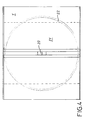
- FIG. 2 shows the top view of the device according to FIG. 1. You can see the raised and lowered box 4 above the Sieve belt 1 and in the four corners of the rectangular box 4 the stops 13 on which the pressure plate 10 at their through the cylinder-piston units anchored to two supports 15 9 caused lifting movement the box 4 for emptying entraining.
- the scraper is on the side of the screen belt 1 14 indicated.
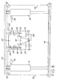
- Fig. 3 shows a partially sectioned side view of a second embodiment of the invention, which is particularly advantageous can be used if a high Fixed content of the press cake 16 is expected. It makes a difference differs from that of FIG. 1 essentially that on the side of the device and at a distance above it Screen belt 1, a rail 17 is provided, in which a the entire width of the belt 1 reaching crushing roller 18 with star-shaped cross section rotatable and is slidably mounted. It is advantageously located on both sides the device has a rail 17, and the crushing roller 18 is between these two rails 17th held. In addition, one is also the entire width of the screen belt 1 covering lifting device 19 is provided, which moved together with the shredding roller 18 can be.
- This crushing roller 18 and lifting device 19 serve the loosening and crushing of the press cake 16 at a particularly high solids content a pressure drainage.
- the press plate 10 is moved up and lifts doing the box 4 from the wire 1 to the crushing roller 18 from. Box 4 has its uppermost position reached, the crushing roller 18 is rotated and together with the lifting device 19 in the or the rails 17 against the mud press cake 16.
- the press cake 16 is lifted off the sieve belt 1 and crushed by the crushing roller 18; the pieces then fall back onto the sieve belt 1. there keep the crushed baffles, not shown Press cake 16 within the cover area of the press plate 10.
- the shredding roller 18 together with the lifting device 19 moved back into their starting position in the rail 17.
- the box 4 is lowered again and the press plate 10 drives again against the dismembered mud press cake and continues to drain this. This process can be repeated a few times until no significant Sludge dewatering takes place more.
- Fig. 4 shows the top view of a third embodiment of the invention, in the middle of the screen belt 1, a cylinder-piston unit 20 arranged as a printing device is and this is a round press plate 21 in and with a round box 22 moves, as described above for Fig. 1, here, too, the press plate 21 with one in FIG. 4 Not shown sliding seal against the inner wall of the Box 22 is sealed.
- the advantage of this embodiment is that the round shape improves the statics and consequently even higher pressures for drainage can be achieved.
- the function and operation are the same as described above for FIG. 1.
- Fig. 5 shows a partially sectioned side view of a Pressure drainage system for sludge, in which over the Sieve belt 1 several, in the example shown three, the drainage units 23 described above one behind the other are arranged.
- the round embodiment is preferred 4 with the round box 22 and the round press plate 21 for use.
- the press plate 10 of several printing devices -
- two hydraulic cylinder-piston units 9, acted upon and moved, must on one as exact a synchronism as possible be observed so that the Press plate 10 remains in a horizontal position, so not canted and on the mud or mud press cake 16 even pressure is applied.
- the press plate 10 is, as described above, of two hydraulic cylinder-piston units 9 acted upon and moved. Near the opposite outer edges the pressing plate 10 are transmission elements 24, attached here in the form of two ropes 24 (or chains), the over pulleys 25 to a center above the press plate 10 arranged balance beam 26 out and on it Ends are attached.
- the balance beam 26 is in his
- the fulcrum is attached to a carriage 27 by means of rollers 28 in guide rails hanging from a frame 29 30 is movable up and down.
- an actuator 31 here in the form of a circular sector plate, for Switches 32 and monitoring devices arranged on both sides of the carriage 27 or emergency switch 33 attached. Via the switches 32 directional control valves 34 are actuated, the hydraulic Pressure (or inflow) in the cylinder-piston units 9 for control the synchronism of the pistons.
- the press plate 10 is applied evenly and moves, the balance beam 26 is in balance and none of the switches 32 and monitor switches 33 will actuated. Will the synchronism of the cylinder-piston units 9 disturbed, the balance beam 26 also gets out of balance and descends to one side or the other.
- the actuator 31 strikes one first the switch 32 on, whereby one of the directional valves 34 the hydraulic pressure (inflow) in one of the cylinder-piston units 9 is increased or decreased until again Synchronism is reached. Should the synchronism on Not because of a more massive disruption this way Have it manufactured and exceed a certain tolerance are, the balance beam 26 pivots and the Actuator 31 finally strikes one of the Monitoring or emergency switch 33 on, so that the system switched off and the fault, e.g. by an alarm or another ad that can be displayed.
- additives are preferably selected that have a have a rough surface and / or have a greater hardness, than the press cake after the gravity drainage phase.
- materials such as sawdust or sewage sludge granulate from a sewage sludge drying plant, as for example in DE 197 04 201 A1 is described.
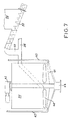
- Fig. 7 shows schematically a device for the introduction of additive (s) in the sludge to be dewatered, the invention together with one described above Drainage device can be used.
- a mixing tank 35 Upstream of a drainage system described above is a mixing tank 35 which is connected via a sludge line 36 can be filled with mud.
- the sludge line 36 is preferably tangential to the outer wall of the mixing container 35 connected.
- an additive container 38 At a branch pipe 37 of the sludge pipe 36 an additive container 38 is connected, from which by means of a conveyor 39, e.g. one Screw conveyor or a conveyor belt, the additive can be fed in the correct ratio.
- a conveyor 39 e.g. one Screw conveyor or a conveyor belt
- the additive can be fed in the correct ratio.
- an agitator 40 with sweeper 41 through a geared motor 42 driven and mixed intensively the sludge with the additives.
- a flocculant known per se is additionally added and with the mixture of sludge and additive mixed.
- Mixing container 35 is preferably above the box 4 with the press plate 10 which can be raised and lowered therein, so the flocculated sludge additive mixture without a pump device, by gravity alone be introduced into the box 4 above the sieve belt 1 can.
- the admixture of additives requires one Volume increase of only sludge to be dewatered 1 -2%, but on the other hand allows an increase the dry matter TS by up to 20% compared to sludge without additives; the volume increase is therefore negligible.
- Another possible additive consists of at the end of the Drainage from the small press 16 obtained Press cake parts or granules, with a special Drying of the press cake or granules is dispensed with can be.
- the press cake 16 has a greater hardness than the sludge after gravity drainage.
- the admixture of the press cake granulate has the advantage that it there is no increase in volume, since only one actually accumulated sludge is added.
Abstract
Description
Der Zusatzstoff besteht vorzugsweise aus einem Gemisch aus nach der Druckentwässerung des Schlamms aus dem verbliebenen Schlammpresskuchen anfallenden, kleineren Presskuchenteilen bzw. Granulat und einem Feuchtigkeit aufnehmenden Stoff von großer Oberfläche und leichtem Gewicht, wie Sägemehl oder gehäkseltem Stroh besteht. Der Anteil des Zusatzstoffes am Schlammpresskuchen sollte vorzugsweise nicht zu groß sein. Durch das Mengenverhältnis wird Gewicht gespart und gleichzeitig die Entwässerung so gefördert, dass mit weniger Druck als bei bekannten Vorrichtungen (etwa 1 -5 bar statt 15 bar) ein gleich gutes oder sogar besseres Ergebnis erzielt wird, also auch Energie eingespart wird. Das Granulat kann unmittelbar dem die Entwässerungsstation nach der Druckentwässerung verlassenden, nur grob zerkleinerten Presskuchen entnommen werden. Der mit der erfindungsgemäßen Vorrichtung erreichte Trockengrad des Presskuchens macht einen besonderen Trockengang überflüssig. Auch das Vermahlen des Presskuchens erübrigt sich und wäre sogar nachteilig, da die Drainagewirkung eines grob, z.B. in Würfelgröße, zerkleinerten Zusatzstoffes deutlich besser ist als die eines fein gemahlenen Zusatzstoffes. Meist zerfällt der Presskuchen beim Verlassen der Entwässerungsstation von selbst in Stücke geeigneter Größe.
- Fig. 1
- eine erste Ausführungsform der erfindungsgemäßen Vorrichtung in Seitenansicht, teilweise geschnitten,
- Fig. 2
- eine Draufsicht auf die Vorrichtung nach Fig. 1,
- Fig. 3
- eine zweite Ausführungsform der erfindungsgemäßen Vorrichtung,
- Fig. 4
- die Draufsicht auf eine dritte Ausführungsform,
- Fig. 5
- die Seitenansicht einer vierten Ausführungsform der Erfindung,
- Fig. 6
- die Seitenansicht einer bei der Erfindung einsetzbaren Gleichlaufregelung und
- Fig. 7
- schematisch eine Vorrichtung für das erfindungsgemäße Einbringen von Zusatzstoffen.
- 1
- Siebband
- 2,3
- Walzen
- 4
- Kasten
- 5
- Dichtung
- 6
- Stützgerüst
- 7
- Lochblech, Spaltsieb
- 8
- Öffnungen
- 9
- Zylinder-Kolben-Einheit, Druckvorrichtung
- 10
- Pressplatte
- 11
- Gleitdichtung
- 12
- Leitung
- 13
- Anschläge
- 14
- Abstreifer
- 15
- Träger
- 16
- Presskuchen
- 17
- Schiene
- 18
- Zerkleinerungswalze
- 19
- Abhebervorrichtung
- 20
- Druckvorrichtung, Zylinder-Kolben-Einheit
- 21
- Pressplatte
- 22
- Kasten
- 23
- Entwässerungseinheit
- 24
- Übertragungselemente (Seil, Kette)
- 25
- Umlenkrollen
- 26
- Waagebalken
- 27
- Wagen
- 28
- Rollen
- 29
- Gestell
- 30
- Führungsschiene
- 31
- Betätigungsvorrichtung
- 32
- Schalter
- 33
- Überwachungsschalter
- 34
- Wegeventil
- 35
- Mischbehälter
- 36
- Schlammleitung
- 37
- Abzweigstutzen
- 38
- Zusatzstoff-Behälter
- 39
- Fördervorrichtung
- 40
- Rührwerk
- 41
- Bodenräumer
- 42
- Getriebemotor
- 43
- Füllrohre
- 44
- Ablauf
Claims (28)
- Vorrichtung zur Entwässerung von Schlämmen und schlammhaltigen Gemischen, wie Klärschlämme, Industrieschlämme und weitere schlammartige Ausgangsprodukte, bei der der flüssige Anteil des zu entwässernden Schlammes durch ein Siebband gepresst wird und der zurückbleibende Schlammpresskuchen abtransportiert wird,
dadurch gekennzeichnet, dass über dem Siebband (1) ein heb- und senkbarer Kasten (4, 22) angeordnet ist, der in seinem abgesenkten Zustand mit einer Dichtung (5) auf dem Siebband (1) aufliegt und mit Schlamm befüllbar ist und dass in dem Kasten (4, 22) eine mit einer Gleitdichtung (11) gegen die Innenwand des Kastens (4, 22) abgedichtete Pressplatte (10, 21) durch mindestens eine Druckvorrichtung (9, 20) auf- und ab bewegbar und mit variablem Druck auf den im Kasten (4) befindlichen Schlamm pressbar ist. - Vorrichtung nach Anspruch 1, dadurch gekennzeichnet, dass als Druckvorrichtung zur Beaufschlagung der Pressplatte (10, 21) mindestens eine hydraulische Zylinder-Kolben-Einheit (9, 20) vorgesehen ist.
- Vorrichtung nach Anspruch 1, dadurch gekennzeichnet, dass
ein Feuchtigkeitsfühler vorgesehen ist, der bei fehlendem Presswasser ein Signal an die Druckvorrichtung (9, 20) gibt und diese solange den Druck auf die Pressplatte (10, 21) erhöht, bis wieder Presswasser vorhanden ist bzw. der Abschaltdruck erreicht ist. - Vorrichtung nach Anspruch 1, dadurch gekennzeichnet, dass in dem Kasten (4) Anschläge (13) vorgesehen sind, an denen die Pressplatte (10) bei ihrer Hubbewegung anschlägt und den Kasten (4) in ihrer weiteren Hubbewegung mitnimmt und vom Siebband (1) abhebt.
- Vorrichtung nach Anspruch 4, dadurch gekennzeichnet, dass der Kasten (4) über Hebevorrichtungen, z.B. Zylinder-Kolben-Einheiten, heb- und senkbar ist.
- Vorrichtung nach Anspruch 1, dadurch gekennzeichnet, dass das Siebband (1) als Endlosband um Rollen (2, 3) geführt ist, von denen mindestens eine als Antriebsrolle für die Bewegung des Siebbandes (1) ausgeführt ist.
- Vorrichtung nach Anspruch 6, dadurch gekennzeichnet, dass an der einen Rolle (3), über die das endlose Siebband (1) geführt ist, ein die gesamte Breite des Siebbandes (1) abdeckender Abstreifer (14) vorgesehen ist.
- Vorrichtung nach Anspruch 6, dadurch gekennzeichnet, dass das Siebband (1) zwischen den Rollen (2, 3) durch ein Stützgerüst (6) getragen ist.
- Vorrichtung nach Anspruch 8, dadurch gekennzeichnet, dass sich zwischen dem Stützgerüst (6) und dem Siebband (1) ein Lochblech oder Spaltsieb (7) befindet.
- Vorrichtung nach Anspruch 1, dadurch gekennzeichnet, dass zur Beaufschlagung der Pressplatte (10) zwei synchron arbeitende hydraulische Zylinder-Kolben-Einheiten (9) vorgesehen sind, deren Gleichlauf durch eine Gleichlaufregelung kontrollierbar ist.
- Vorrichtung nach Anspruch 10, dadurch gekennzeichnet, dass an der Pressplatte (10) einander gegenüberliegend die Bewegung der Pressplatte (10) übertragende Übertragungselemente (24) vorgesehen sind, die mit den freien Enden eines Waagebalkens (26) verbunden sind, und dass an dem Waagebalken (26) eine Betätigungsvorrichtung (31) angeordnet ist, durch die beim Ausschlagen des Waagebalkens (26) Schalter (32, 33) betätigbar sind, über die der hydraulische Druck in (Zufluss zu) den Zylinder-Kolben-Einheiten (9) steuerbar ist.
- Vorrichtung nach Anspruch 11, dadurch gekennzeichnet, dass an der Pressplatte (10) sich diagonal gegenüberliegend als Übertragungselemente je ein Seil (24) oder eine Kette befestigt ist, von denen jede über Umlenkrollen (25) geführt und mit dem jeweils anderen freien Ende des Waagebalkens (26) verbunden ist, und dass der Waagebalken (26) in seinem Drehpunkt mit einem Wagen (27) fest verbunden ist, der mittels Rollen (28) in von einem feststehenden Gestell (29) herabhängend angebrachten Führungsschienen (30) gegenläufig zur Pressplatte (10) auf- und ab bewegbar ist.
- Vorrichtung nach Anspruch 11, dadurch gekennzeichnet, dass beim Auslenken des Waagebalkens (26) durch die daran vorgesehene Betätigungsvorrichtung (31) zunächst einer der Schalter (32) betätigbar ist, über den der hydraulische Druck in (Zufluss zu) den Zylinder-Kolben-Einheiten (9) steuerbar ist, und dass bei weiterem Auslenken des Waagebalkens (26) ein Überwachungs- oder Notschalter (33) betätigbar, über den die Anlage abschaltbar und/oder die Störung anzeigbar ist.
- Vorrichtung nach Anspruch 12, dadurch gekennzeichnet, dass die Schalter (32, 33) am Wagen (27) beidseitig der am Waagebalken (26) befestigten Betätigungsvorrichtung (31) angeordnet sind.
- Vorrichtung nach Anspruch 1, dadurch gekennzeichnet, dass der Kasten (22) einen kreisrunden Querschnitt aufweist, die Pressplatte (21) kreisrund ist und eine einzige, zentrale Druckvorrichtung (Zylinder-Kolben-Einheit) (20) zur Beaufschlagung der Pressplatte (21) vorgesehen ist.
- Vorrichtung nach Anspruch 1, dadurch gekennzeichnet, dass seitlich neben und über dem Siebband (1) mindestens eine Schiene (17) angeordnet ist, in der eine die gesamte Breite des Siebbandes (1) abdeckende Zerkleinerungswalze (18) verschiebbar ist.
- Vorrichtung nach Anspruch 16, dadurch gekennzeichnet, dass mit der Zerkleinerungswalze (18) auch eine die gesamte Breite des Siebbandes (1) abdeckende Abhebevorrichtung (19) in der Schiene (17) verschiebbar ist.
- Vorrichtung nach Anspruch 1, dadurch gekennzeichnet, dass dem Kasten (4, 22) ein Mischbehälter (35) mit Rührwerk (40) zur Beimischung eines grob zerkleinerten, drainage-fördernden Zusatzstoffes zum zu entwässernden Schlamm vorgeschaltet ist.
- Vorrichtung nach Anspruch 18, dadurch gekennzeichnet, dass die Schlammleitung (36), über die der zu entwässernde Schlamm in den Mischbehälter (35) einbringbar ist, über einen Abzweigstutzen (37) Verbindung hat mit einem Zusatzstoff-Behälter (38) aus dem der Zusatzstoff beigemischt wird.
- Vorrichtung nach Anspruch 19, dadurch gekennzeichnet, dass zwischen dem Abzweigstutzen (37) und dem Zusatzstoff-Behälter (38) eine Fördervorrichtung (43) angeordnet ist, über die der Zusatzstoff dosiert zuführbar ist.
- Vorrichtung nach Anspruch 18, dadurch gekennzeichnet, dass am Umfang des Mischbehälters (35) gleichmäßig verteilt mehrere Füllrohre (43) angeordnet sind, durch die ein an sich bekanntes Flockungsmittel beimischbar ist.
- Vorrichtung nach Anspruch 18, dadurch gekennzeichnet, dass im Mischbehälter (35) ein Rührwerk (40) mit Bodenräumer (41) vorgesehen ist.
- Vorrichtung nach Anspruch 18, dadurch gekennzeichnet, dass der Zusatzstoff eine rauhe Oberfläche und eine größere Härte aufweist als der zu entwässernde Schlamm nach einer Vorentwässerung durch Schwerkraft.
- Vorrichtung nach Anspruch 18, dadurch gekennzeichnet, dass der Zusatzstoff aus einem Gemisch aus unmittelbar nach der Druckentwässerung des Schlamms aus dem verbliebenen Schlammpresskuchen anfallenden, kleinen Schlammpresskuchenteilen bzw. Granulat und einem Feuchtigkeit aufnehmenden Stoff von hoher Oberfläche und leichtem Gewicht, wie Sägemehl oder gehäkseltem Stroh besteht.
- Vorrichtung nach Anspruch 1, dadurch gekennzeichnet, dass über dem Siebband (1) mehrere Entwässerungseinheiten (23) bestehend aus dem heb- und senkbaren Kasten (4, 22) und der durch eine Druckvorrichtung (9, 20) darin aufund ab bewegbaren Pressplatte (10, 21) hintereinander angeordnet sind.
- Verfahren zur Entwässerung von Schlämmen und schlammhaltigen Gemischen, wie Klärschlämme, Industrieschlämme und weitere schlammartige Ausgangsprodukte, bei dem der flüssige Anteil des zu entwässernden Schlamms durch ein Siebband gepresst und der zurückbleibende Schlammpresskuchen abtransportiert wird, dadurch gekennzeichnet, dass das Schlamm-Wasser-Gemisch vor dem Pressvorgang allein durch Schwerkraft statisch bis über 50% vorentwässert wird.
- Verfahren nach Anspruch 26, dadurch gekennzeichnet, dass der zu entwässernde Schlamm vor der Zugabe von Flockungsmittel mit einem grob zerkleinerten, drainage-fördernden Zusatzstoff vermischt wird.
- Verfahren nach Anspruch 26, dadurch gekennzeichnet, dass der zu entwässernde Schlamm vor der Vorentwässerung mit einem grob zerkleinerten, drainage-fördernden Zusatzstoff vermischt wird.
Applications Claiming Priority (2)
| Application Number | Priority Date | Filing Date | Title |
|---|---|---|---|
| DE10207451A DE10207451A1 (de) | 2002-01-22 | 2002-01-22 | Vorrichtung und Verfahren zur Entwässerung von Schlämmen |
| DE10207451 | 2002-01-22 |
Publications (2)
| Publication Number | Publication Date |
|---|---|
| EP1329427A2 true EP1329427A2 (de) | 2003-07-23 |
| EP1329427A3 EP1329427A3 (de) | 2003-10-08 |
Family
ID=7713896
Family Applications (1)
| Application Number | Title | Priority Date | Filing Date |
|---|---|---|---|
| EP03001150A Withdrawn EP1329427A3 (de) | 2002-01-22 | 2003-01-21 | Vorrichtung und Verfahren zur Entwässerung von Schlämmen |
Country Status (2)
| Country | Link |
|---|---|
| EP (1) | EP1329427A3 (de) |
| DE (1) | DE10207451A1 (de) |
Cited By (10)
| Publication number | Priority date | Publication date | Assignee | Title |
|---|---|---|---|---|
| EP1862205A1 (de) * | 2005-03-25 | 2007-12-05 | Tsukishima Kikai Co., Ltd. | Feststoff- und flüssigkeitsseparator und feststoff- und füssigkeitstrennverfahren |
| CN102343170A (zh) * | 2011-08-30 | 2012-02-08 | 中交天津港航勘察设计研究院有限公司 | 一种脱水干化装置 |
| CN105289066A (zh) * | 2015-11-05 | 2016-02-03 | 茆正伟 | 一种污泥脱水机 |
| CN106365409A (zh) * | 2016-10-20 | 2017-02-01 | 林玉瑶 | 泥浆干化机 |
| CN107569888A (zh) * | 2017-11-09 | 2018-01-12 | 高月江 | 一种便捷型污泥脱水装置 |
| CN108609830A (zh) * | 2018-05-31 | 2018-10-02 | 林丽敏 | 一种污泥干化装置 |
| CN111138062A (zh) * | 2020-03-06 | 2020-05-12 | 浙江金祖环境治理设备股份有限公司 | 一种泥浆压滤机 |
| CN113087349A (zh) * | 2021-05-26 | 2021-07-09 | 盘锦环能科技有限公司 | 一种污泥皮带深度脱水方法 |
| CN113248099A (zh) * | 2021-05-20 | 2021-08-13 | 霍邱县昌荣鹅业养殖有限公司 | 一种用于家庭农场中禽舍的废弃物处理设备 |
| CN117482610A (zh) * | 2024-01-02 | 2024-02-02 | 中信重工机械股份有限公司 | 一种矿浆品位仪的压榨装置及滤饼压榨方法 |
Citations (7)
| Publication number | Priority date | Publication date | Assignee | Title |
|---|---|---|---|---|
| US4008158A (en) * | 1974-10-31 | 1977-02-15 | Envirotech Corporation | Dewatering machine |
| US4158627A (en) * | 1976-02-27 | 1979-06-19 | Ab Kalle-Regulatorer | Method and apparatus for extracting waste material |
| GB2086751A (en) * | 1980-08-27 | 1982-05-19 | Lambert & Cie | Platen press |
| DE3150641A1 (de) * | 1981-12-21 | 1983-06-30 | R.S. Rösler KG Zweigniederlassung Hausen b. Lichtenfels, 8621 Banz | Vorrichtung zum filtern und eindicken von duennschlamm |
| US4686043A (en) * | 1985-03-27 | 1987-08-11 | Kabushiki Kaisha Yagishita | Batch type filter system |
| US5386768A (en) * | 1993-03-26 | 1995-02-07 | Roediger Pittsburgh, Inc. | Apparatus for dewatering sludge |
| WO2000003782A1 (en) * | 1998-07-16 | 2000-01-27 | Novus International, Inc. | Endless band filter with pressure means and process for filtering |
Family Cites Families (3)
| Publication number | Priority date | Publication date | Assignee | Title |
|---|---|---|---|---|
| DE3221435C2 (de) * | 1982-06-07 | 1985-10-31 | Hitachi Plant Engineering & Construction Co., Ltd., Tokio/Tokyo | Siebbandpresse zum Entwässern von eingedicktem Klärschlamm |
| DE3734974A1 (de) * | 1986-10-21 | 1989-04-20 | Baehr Albert | Vorrichtung zum entwaessern von schlamm und aehnlichen substanzen |
| DE3635766A1 (de) * | 1986-10-21 | 1988-04-28 | Albert Baehr | Vorrichtung zum entwaessern von schlamm und aehnlichen substanzen |
-
2002
- 2002-01-22 DE DE10207451A patent/DE10207451A1/de not_active Withdrawn
-
2003
- 2003-01-21 EP EP03001150A patent/EP1329427A3/de not_active Withdrawn
Patent Citations (7)
| Publication number | Priority date | Publication date | Assignee | Title |
|---|---|---|---|---|
| US4008158A (en) * | 1974-10-31 | 1977-02-15 | Envirotech Corporation | Dewatering machine |
| US4158627A (en) * | 1976-02-27 | 1979-06-19 | Ab Kalle-Regulatorer | Method and apparatus for extracting waste material |
| GB2086751A (en) * | 1980-08-27 | 1982-05-19 | Lambert & Cie | Platen press |
| DE3150641A1 (de) * | 1981-12-21 | 1983-06-30 | R.S. Rösler KG Zweigniederlassung Hausen b. Lichtenfels, 8621 Banz | Vorrichtung zum filtern und eindicken von duennschlamm |
| US4686043A (en) * | 1985-03-27 | 1987-08-11 | Kabushiki Kaisha Yagishita | Batch type filter system |
| US5386768A (en) * | 1993-03-26 | 1995-02-07 | Roediger Pittsburgh, Inc. | Apparatus for dewatering sludge |
| WO2000003782A1 (en) * | 1998-07-16 | 2000-01-27 | Novus International, Inc. | Endless band filter with pressure means and process for filtering |
Cited By (11)
| Publication number | Priority date | Publication date | Assignee | Title |
|---|---|---|---|---|
| EP1862205A1 (de) * | 2005-03-25 | 2007-12-05 | Tsukishima Kikai Co., Ltd. | Feststoff- und flüssigkeitsseparator und feststoff- und füssigkeitstrennverfahren |
| EP1862205A4 (de) * | 2005-03-25 | 2010-05-05 | Tsukishima Kikai Co | Feststoff- und flüssigkeitsseparator und feststoff- und füssigkeitstrennverfahren |
| CN102343170A (zh) * | 2011-08-30 | 2012-02-08 | 中交天津港航勘察设计研究院有限公司 | 一种脱水干化装置 |
| CN105289066A (zh) * | 2015-11-05 | 2016-02-03 | 茆正伟 | 一种污泥脱水机 |
| CN106365409A (zh) * | 2016-10-20 | 2017-02-01 | 林玉瑶 | 泥浆干化机 |
| CN107569888A (zh) * | 2017-11-09 | 2018-01-12 | 高月江 | 一种便捷型污泥脱水装置 |
| CN108609830A (zh) * | 2018-05-31 | 2018-10-02 | 林丽敏 | 一种污泥干化装置 |
| CN111138062A (zh) * | 2020-03-06 | 2020-05-12 | 浙江金祖环境治理设备股份有限公司 | 一种泥浆压滤机 |
| CN113248099A (zh) * | 2021-05-20 | 2021-08-13 | 霍邱县昌荣鹅业养殖有限公司 | 一种用于家庭农场中禽舍的废弃物处理设备 |
| CN113087349A (zh) * | 2021-05-26 | 2021-07-09 | 盘锦环能科技有限公司 | 一种污泥皮带深度脱水方法 |
| CN117482610A (zh) * | 2024-01-02 | 2024-02-02 | 中信重工机械股份有限公司 | 一种矿浆品位仪的压榨装置及滤饼压榨方法 |
Also Published As
| Publication number | Publication date |
|---|---|
| DE10207451A1 (de) | 2003-08-07 |
| EP1329427A3 (de) | 2003-10-08 |
Similar Documents
| Publication | Publication Date | Title |
|---|---|---|
| EP0344152B1 (de) | Verfahren zum entwässern von abwasserschlamm und anlage zur durchführung des verfahrens | |
| DE2844697C2 (de) | Filterpresse zum Entwässern von Schlamm und ähnlichen Substanzen | |
| EP0264899B1 (de) | Vorrichtung zum Entwässern von Schlamm und ähnlichen Substanzen | |
| DE2821365C3 (de) | Filtervorrichtung zum Entwässern von schlammförmigem Material | |
| EP1329427A2 (de) | Vorrichtung und Verfahren zur Entwässerung von Schlämmen | |
| DE2705285A1 (de) | Verfahren und vorrichtung zum entwaessern von schlamm | |
| DE2605040A1 (de) | Vorrichtung zur kontinuierlichen druckfilterung von in fluessigkeiten enthaltenen feststoffen | |
| DE19932416A1 (de) | Vorrichtung zum Entwässern von Schlamm | |
| DE3736657C2 (de) | ||
| EP1013614B1 (de) | Entwässerung von Fermentationsprodukten mit Schneckenpresse | |
| CN213506513U (zh) | 一种用于市政污水处理厂的污泥处理装置 | |
| DE1964950A1 (de) | Bandfilter zum Entwaessern von Suspensionen,insbesondere von bei der Abwasseraufbereitung anfallendem Klaerschlamm | |
| DE2115159B2 (de) | Vorrichtung zum extrahieren von in pflanzlichem material enthaltenen substanzen durch diffusion | |
| DE2522505B2 (de) | Verfahren und Vorrichtung zum Entwässern von Schlämmen | |
| DE2244917A1 (de) | Verfahren und einrichtung zum beschicken einer filtervorrichtung | |
| DE1461500B1 (de) | Etagendruckfilter | |
| EP0396079A2 (de) | Vorrichtung zum Entwässern von Schlamm und ähnlichen Substanzen | |
| DE2510283C3 (de) | Mit Hilfe eines Lastkraftwagens transportierbare Vorrichtung zum Abscheiden von Feststoffen aus schlammartigem Müll oder Abfall | |
| DE3150641A1 (de) | Vorrichtung zum filtern und eindicken von duennschlamm | |
| DE102014117066B3 (de) | Walzenpresse | |
| AT396923B (de) | Verfahren und trenneinrichtung zum auftrennen bzw. entwässern von flüssigkeit-feststoff-gemischen | |
| DE2434943A1 (de) | Vorrichtung zur entfernung von fluessigkeit aus einer suspension | |
| WO1995032159A1 (de) | Filtrieranlage, insbesondere zur minderung des wassergehaltes von schlamm | |
| DE3221435A1 (de) | Siebbandpresse | |
| AT381647B (de) | Bandfilterpresse |
Legal Events
| Date | Code | Title | Description |
|---|---|---|---|
| PUAI | Public reference made under article 153(3) epc to a published international application that has entered the european phase |
Free format text: ORIGINAL CODE: 0009012 |
|
| AK | Designated contracting states |
Designated state(s): AT BE BG CH CY CZ DE DK EE ES FI FR GB GR HU IE IT LI LU MC NL PT SE SI SK TR |
|
| AX | Request for extension of the european patent |
Extension state: AL LT LV MK RO |
|
| PUAL | Search report despatched |
Free format text: ORIGINAL CODE: 0009013 |
|
| AK | Designated contracting states |
Kind code of ref document: A3 Designated state(s): AT BE BG CH CY CZ DE DK EE ES FI FR GB GR HU IE IT LI LU MC NL PT SE SI SK TR |
|
| AX | Request for extension of the european patent |
Extension state: AL LT LV MK RO |
|
| 17P | Request for examination filed |
Effective date: 20040317 |
|
| AKX | Designation fees paid |
Designated state(s): AT BE BG CH CY CZ DE DK EE ES FI FR GB GR HU IE IT LI LU MC NL PT SE SI SK TR |
|
| 17Q | First examination report despatched |
Effective date: 20050512 |
|
| STAA | Information on the status of an ep patent application or granted ep patent |
Free format text: STATUS: THE APPLICATION IS DEEMED TO BE WITHDRAWN |
|
| 18D | Application deemed to be withdrawn |
Effective date: 20080801 |