EP1328355B1 - Fahrbare siebanlage - Google Patents
Fahrbare siebanlage Download PDFInfo
- Publication number
- EP1328355B1 EP1328355B1 EP01982016A EP01982016A EP1328355B1 EP 1328355 B1 EP1328355 B1 EP 1328355B1 EP 01982016 A EP01982016 A EP 01982016A EP 01982016 A EP01982016 A EP 01982016A EP 1328355 B1 EP1328355 B1 EP 1328355B1
- Authority
- EP
- European Patent Office
- Prior art keywords
- screener
- support frame
- sized particles
- small
- screening unit
- Prior art date
- Legal status (The legal status is an assumption and is not a legal conclusion. Google has not performed a legal analysis and makes no representation as to the accuracy of the status listed.)
- Expired - Lifetime
Links
Images


Classifications
-
- B—PERFORMING OPERATIONS; TRANSPORTING
- B07—SEPARATING SOLIDS FROM SOLIDS; SORTING
- B07B—SEPARATING SOLIDS FROM SOLIDS BY SIEVING, SCREENING, SIFTING OR BY USING GAS CURRENTS; SEPARATING BY OTHER DRY METHODS APPLICABLE TO BULK MATERIAL, e.g. LOOSE ARTICLES FIT TO BE HANDLED LIKE BULK MATERIAL
- B07B9/00—Combinations of apparatus for screening or sifting or for separating solids from solids using gas currents; General arrangement of plant, e.g. flow sheets
-
- B—PERFORMING OPERATIONS; TRANSPORTING
- B07—SEPARATING SOLIDS FROM SOLIDS; SORTING
- B07B—SEPARATING SOLIDS FROM SOLIDS BY SIEVING, SCREENING, SIFTING OR BY USING GAS CURRENTS; SEPARATING BY OTHER DRY METHODS APPLICABLE TO BULK MATERIAL, e.g. LOOSE ARTICLES FIT TO BE HANDLED LIKE BULK MATERIAL
- B07B1/00—Sieving, screening, sifting, or sorting solid materials using networks, gratings, grids, or the like
- B07B1/005—Transportable screening plants
Definitions
- a mobile screening unit for screening bulky material comprising the features of claim 1.
- Preferred embodiments and beneficial details of the new mobile screening unit are disclosed in dependent claims 2 through 14.
- the screening unit 1 illustrated in the accompanying drawings is a mobile screening unit 1 for screening bulk material 3 containing at least large-sized, medium-sized, and small-sized particles 5,7,9.
- the screening unit 1 comprises a first screener 11, a second screener 13, and an elongated mobile support frame 15 having a longitudinal axis 17.
- the first screener 11 is mounted to the support frame 15 and extends longitudinally thereon.
- the first screener 11 has an inlet 19 for receiving the bulk material 3, a first outlet 21 for releasing large-sized particles 5, and a second outlet 23 for releasing medium-sized and small-sized particles 7,9.
- first and second directions 25, 33 as illustrated in the accompanying drawings are directed in opposite ways, for example in figure 3, the first direction 25 points to the left whereas the second direction 33 points to the right, it is worth mentioning that the mobile screening unit 1 and the components thereof, namely but not exclusively the first and second screeners 11, 13, may be disposed otherwise so that both directions 25, 33 point towards the same way, as apparent to a person skilled in the art, so long as the directions 25, 33 are disposed along the longitudinal axis 17 of the support frame 15, according to the present invention.
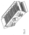
- the mobile screening unit 1 comprises a feeding hopper 35 for accumulating the bulk material 3.
- the feeding hopper 35 is mounted to the support frame 15 and extends longitudinally thereon between the first screener 11 and the second screener 13, as better shown in figures 2 and 3.
- the feeding hopper 35 has an inlet 37 for receiving the bulk material 3 and an outlet 39 for feeding a feeding conveyor 41 positioned to receive the bulk material 3 from the outlet 39 of the feeding hopper 35 and convey the same in the first direction 25 to the inlet 19 of the first screener 11.
- the feeding hopper 35 comprises retractable rear and lateral side panels 43.
- the side panels 43 are deployed in the working position, as shown in figure 2, in order to increase the capacity of the feeding hopper 35.
- the direction of flow of the bulk material 3 in the feeding hopper 35, on the feeding conveyor 41, is preferably done along the longitudinal axis of the support frame 15 which enables the feeding hopper 35 to have side panels 43 having a length of at least 12'. This enables, among other things, to load the feeding hopper 35 by the side of the mobile screening unit 1 with most models of loading shovels known in the industry (the shovels of the loaders used in the industry have generally a length located between 9' and 12').
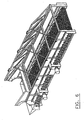
- the first screener 11 preferably consists of a vibrating screener, such as the one illustrated in Figure 5
- the second screener 13 preferably consists of a rotating screener, such as the one illustrated in figure 7.
- the bulk material 3 to be screened is unloaded directly at the inlet 19 of the first screener 11 on the first section of fingers 65 thereof by means of the feeding conveyor 41 cooperating with the material reserve contained in the feeding hopper 35, thereby enabling a constant and continuous feeding of the first screener 11.
- the bulk material 3 can be unloaded directly at the inlet 19 of the first screener 11 by other appropriate feeding means such as an excavator, a loader, a mechanical shovel or even an auxiliary conveyor for example.
- the direct loading onto the first screener 11 by these feeding means may be deemed more suitable if the bulk material 3 to be screened might risk of blocking in the feeding hopper 35 or either damage it if it contains pieces which are excessively large and/or excessively heavy.
- the material released from the first screener 11 is preferably exempt of any large-sized particles 5, so that the secondary screening can be easily carried out by a rotating screener for example, without risking damaging the screening screens thereof.
- the secondary screening may also be carried out by means of a star screener such as the one shown in figure 6 for example, without the risk of damaging the stars or the star shafts thereof.
- the secondary screening may be carried out by means of another vibrating screener for example. This latter approach turns out to be more efficient and quicker than with a rotating screener or a star screener when the material to be screened contains aggregates.
- both the first and second screeners 11,13 are disposed substantially along the longitudinal axis 17 of the support frame 15 so as to enable increased screening lengths thereof, and therefore enable increased screening capacities thereof, and since the large-sized particles 5 of the bulk material 3 are removed at the first screener 11, the present invention enables to obtain an increased screening rate at the second screener stage, than what is possible with the mobile screening units known in the prior art which have screeners disposed otherwise.
- the recovering conveyor 47 then preferably unloads itself at its outlet end 49 onto a piling conveyor 51 of small-sized particles.
- the piling conveyor 51 of small-sized particles 9 preferably folds itself towards the front of the support frame 15 along the longitudinal axis thereof.
- the piling conveyor 51 preferably unfolds itself perpendicularly to the longitudinal axis 17 of the support frame 15 in order to distance the piling of the small-sized particles 9 so as to produce a substantially-sized pile 53 of small-sized particles 9 which will be far away enough from the mobile screening unit 1 so as to not interfere therewith.
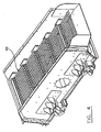
- the support frame 15 preferably comprises a coupling device 59 for removably coupling the support frame 15 to hauling means (not shown) and a wheeled assembly 61 operatively connected to the support frame 15 for allowing transportation of the screening unit 1 by the hauling means, such as a tractor-trailer for example.
- the mobile screening unit 1 preferably comprises a set of axles and wheels, a suspension system, a suitable braking system, and signaling devices, all of which are preferably compliant for safe transportation on roads and highways.
- the mobile screening unit 1 in its transportation configuration, as shown in figure 1, preferably complies also with road requirements in terms of length, width and height allowable, by virtue of its foldable components, as well as due to the longitudinal disposition of the first and second screeners 11,13.
- the support frame 15 also preferably comprises hydraulic support legs 63 for stabilizing the support frame 15 of the mobile screening unit 1 during stationary work operation of the screening unit 1.
Claims (14)
- Eine fahrbare Siebanlage (1) zum Sieben von Schüttgut, diese Siebanlage umfassend:- einen länglichen fahrbaren, eine Längsachse habenden Stützrahmen (15);- einen an dem Stützrahmen befestigter und sich darauf der Länge nach erstreckender ersten Sieber (11), der erste Sieber umfassend:- einen Einlass (19) zum Aufnehmen von grossformatige, mittel-formatige und klein-formatige Partikel umfassendem Schüttgut,- einen ersten Auslass (21) zum Abgeben von grossformatigen Partikeln, und- einen zweiten Auslass (23) zum Abgeben von mittel-formatigen und klein-formatigen Partikeln, der erste Sieber wird verwendet für das Sieben des Schüttguts entlang einer ersten Richtung im Wesentlichen parallel zu der Längsachse des Stützrahmens;- einen an dem Stützrahmen befestigter und sich darauf der Länge nach erstreckender zweiten Sieber (13), der zweite Sieber umfassend:der zweite Sieber wird verwendet für das Aussieben der mittel-formatigen Partikel von den klein-formatigen Partikeln entlang einer zweiten Richtung im Wesentlichen parallel zu der Längsachse des Stützrahmens,- einen Einlass (27) zum Aufnehmen von mittel-formatigen und klein-formatigen von dem ersten Sieber zugeführten Partikeln,- einen ersten Auslass (29) zum Abgeben von mittel-formatigen Partikeln, und- einen zweiten Auslass (31) zum Abgeben von klein-formatigen Partikeln,
dadurch gekennzeichnet, dass sie umfasst:- ein Zufuhrmagazin (35) zum Sammeln von Schüttgut, das Zufuhrmagazin (35) ist am Stützrahmen befestigt und erstreckt sich darauf der Länge nach zwischen dem ersten Sieber und dem zweiten Sieber und hat einen Einlass (37) zum Aufnehmen von Schüttgut und einen Auslass (39) zum Abgeben von Schüttgut; und- einen Zufuhrförderer (41) angeordnet um das von dem Auslass des Zufuhrmagazins abgegebene Schüttgut zum empfangen und dasselbe in die erste Richtung zu dem Einlass des ersten Siebers zu fördern. - Eine fahrbare Siebanlage gemäss Anspruch 1,
dadurch gekennzeichnet, dass
sie einen an dem Stützrahmen befestigten und sich darauf der Länge nach erstreckenden Übergangsförderer (45) umfasst, der Übergangsförderer ist angeordnet um die von dem zweiten Auslass des ersten Siebers abgegebenen mittel-formatigen und klein-formatigen Partikel aufzunehmen und dieselben in die zweite Richtung zu dem Einlass des zweiten Siebers zu fördern. - Eine fahrbare Siebanlage gemäss Anspruch 1 oder 2,
dadurch gekennzeichnet, dass
sie einen an dem Stützrahmen befestigten und sich darauf der Länge nach erstreckenden Rückgewinnungsförderer (47) umfasst, der Rückgewinnungsförderer ist angeordnet um die von dem zweiten Auslass des zweiten Siebers abgegebenen klein-formatigen Partikel aufzunehmen und dieselben in die erste Richtung zu einem Auslassende davon zu fördern. - Eine fahrbare Siebanlage gemäss Anspruch 3,
dadurch gekennzeichnet, dass
sie einen an dem Stützrahmen befestigten Anhäufungsförderer (51) zum Aufnehmen der klein-formatigen Partikel von dem Auslassende des Rückgewinnungsförderers und zum Bilden eines Haufens von klein-formatigen Partikeln abseits vom Stützrahmen umfasst, der Anhäufungsförderer ist beweglich in Bezug auf den Stützrahmen zwischen einer eingeklappten Position wo er gegen den Stützrahmen geklappt ist und einer verlängerten Position wo er sich senkrecht zu der Längsachse des Stützrahmens erstreckt. - Eine fahrbare Siebanlage gemäss einem der Ansprüche 1 bis 4,
dadurch gekennzeichnet, dass
sie einen an dem rückwärtigen Ende des Stützrahmens befestigten Anhäufungsförderer (55) zum Aufnehmen der mittel-formatigen Partikel von dem ersten Auslass des zweiten Siebers und zum Bilden eines Haufens von mittel-formatigen Partikeln am rückwärtigen Ende des Stützrahmens umfasst, der genannte Anhäufungsförderer ist beweglich zwischen einer eingeklappten Position wo er gegen das rückwärtige Ende des Stützrahmens geklappt ist und einer verlängerten Position wo er sich in der selben Linie erstreckt wie der Stützrahmen. - Eine fahrbare Siebanlage gemäss einem der Ansprüche 1 bis 5,
dadurch gekennzeichnet, dass
der erste Sieber aus der Gruppe ausgewählt ist, die aus einem Vibrationssieber, einem Scheibensieber und einem Hochleistungs-Sternsieber besteht. - Eine fahrbare Siebanlage gemäss einem der Ansprüche 1 bis 6,
dadurch gekennzeichnet, dass
der erste Sieber ein Vibrationssieber ist. - Eine fahrbare Siebanlage gemäss einem der Ansprüche 1 bis 7,
dadurch gekennzeichnet, dass
der zweite Sieber aus der Gruppe ausgewählt ist, die aus einem Vibrationssieber, einem Sternsieber, einem rotierenden Sieber, einem Satellitensieber, einem Kreiselsieber und einem zweistufigen Vibrationssieber besteht. - Eine fahrbare Siebanlage gemäss einem der Ansprüche 1 bis 8,
dadurch gekennzeichnet, dass der zweite Sieber ein rotierender Sieber ist. - Eine fahrbare Siebanlage gemäss Anspruch 1, dadurch gekennzeichnet, dass
das Zufuhrmagazin einklappbare Rück- und äussere Seitenpanele (43) umfasst. - Eine fahrbare Siebanlage gemäss einem der Ansprüche 1 bis 10, dadurch gekennzeichnet, dass
der Stützrahmen umfasst:- eine Koppelvorrichtung (59) zum lösbaren Koppeln des Stützrahmens an Schleppmittel; und- einen fahrbaren im Betrieb an dem Stützrahmen befestigten Aufbau (61) um Transport der Siebanlage durch das Schleppmittel zu ermöglichen. - Eine fahrbare Siebanlage gemäss einem der Ansprüche 1 bis 11, dadurch gekennzeichnet, dass
der Stützrahmen hydraulische Stützfüße (63) zum Stabilisieren des Stützrahmens der Siebanlage während dem stationären Arbeitsbetrieb der Siebanlage umfasst. - Eine fahrbare Siebanlage gemäss einem der Ansprüche 1 bis 12, dadurch gekennzeichnet, dass
der zweite Sieber ein doppelstufiger, einen ersten Siebboden für das Aussieben der mittel-formatigen Partikel von den klein-formatigen Partikeln und einen zweiten Siebboden für das weitere Sieben der klein-formatigen Partikel in grobe klein-formatige Partikel und feinere klein-formatige Partikel umfasst. - Eine fahrbare Siebanlage gemäss Anspruch 1, dadurch gekennzeichnet, dass sie umfasst:- einen an dem Stützrahmen befestigten und sich darauf der Länge nach erstreckenden Übergangsförderer (45), der Übergangsförderer ist angeordnet um die von dem zweiten Auslass des ersten Siebers abgegebenen mittel-formatigen und klein-formatigen Partikel aufzunehmen und dieselben in die zweite Richtung zu dem Einlass des zweiten Siebers zu fördern;- einen an dem Stützrahmen befestigten und sich darauf der Länge nach erstreckenden Rückgewinnungsförderer (47), der Rückgewinnungsförderer ist angeordnet um die von dem zweiten Auslass des zweiten Siebers abgegebenen klein-formatigen Partikel aufzunehmen und dieselben in die erste Richtung zu einem Auslassende davon zu fördern;- einen an dem Stützrahmen befestigten ersten Anhäufungsförderer (51) zum Aufnehmen der klein-formatigen Partikel von dem Auslassende des Rückgewinnungsförderers und Bilden eines Haufens klein-formatiger Partikel abseits des Stützrahmens, der Anhäufungsförderer ist beweglich in Bezug auf den Stützrahmen zwischen einer eingeklappten Position wo er entlang dessen Längsachse gegen den Stützrahmen geklappt ist und einer verlängerten Position wo er sich senkrecht zu der Längsachse des Stützrahmens erstreckt; und- einen an dem rückwärtigen Ende des Stützrahmens befestigten zweiten Anhäufungsförderer (55) zum Aufnehmen der mittel-formatigen Partikel von dem ersten Auslass des zweiten Siebers und zum Bilden eines Haufens von mittel-formatigen Partikeln beim rückwärtigen Ende des Stützrahmens, der genannte Anhäufungsförderer ist beweglich zwischen einer eingeklappten Position wo er gegen das rückwärtige Ende des Stützrahmens geklappt ist und einer verlängerten Position wo er sich in der selben Linie erstreckt wie der Stützrahmen.
Applications Claiming Priority (3)
| Application Number | Priority Date | Filing Date | Title |
|---|---|---|---|
| CA2324498 | 2000-10-27 | ||
| CA002324498A CA2324498A1 (fr) | 2000-10-27 | 2000-10-27 | Tamiseur combine |
| PCT/CA2001/001525 WO2002034419A1 (en) | 2000-10-27 | 2001-10-26 | Mobile screening unit |
Publications (3)
| Publication Number | Publication Date |
|---|---|
| EP1328355A1 EP1328355A1 (de) | 2003-07-23 |
| EP1328355B1 true EP1328355B1 (de) | 2006-05-24 |
| EP1328355B8 EP1328355B8 (de) | 2006-07-26 |
Family
ID=4167469
Family Applications (1)
| Application Number | Title | Priority Date | Filing Date |
|---|---|---|---|
| EP01982016A Expired - Lifetime EP1328355B8 (de) | 2000-10-27 | 2001-10-26 | Fahrbare siebanlage |
Country Status (9)
| Country | Link |
|---|---|
| US (1) | US6843376B2 (de) |
| EP (1) | EP1328355B8 (de) |
| JP (1) | JP3996847B2 (de) |
| AT (1) | ATE327051T1 (de) |
| AU (1) | AU2002213717A1 (de) |
| CA (1) | CA2324498A1 (de) |
| DE (1) | DE60119951T2 (de) |
| ES (1) | ES2266277T3 (de) |
| WO (1) | WO2002034419A1 (de) |
Families Citing this family (35)
| Publication number | Priority date | Publication date | Assignee | Title |
|---|---|---|---|---|
| ATE435073T1 (de) * | 2002-02-12 | 2009-07-15 | Extec Screens & Crushers Ltd | Klassieranlage |
| FI20021428A (fi) * | 2002-07-31 | 2004-02-01 | Metso Minerals Tampere Oy | Menetelmä seulontakoneen ohjaamiseksi ja seulontakone |
| GB2393638B (en) * | 2002-08-22 | 2006-04-12 | Carnell Contractors Ltd | Aggregate cleaning |
| DE20309857U1 (de) * | 2003-06-25 | 2004-11-04 | Doppstadt Calbe Gmbh | Trommelsiebmaschine |
| NZ528128A (en) * | 2003-09-09 | 2006-04-28 | Rocktec Ltd | Improved material sorter |
| US6988624B2 (en) * | 2003-10-31 | 2006-01-24 | Macnaughton Douglas J | Vibrating screen with a loading pan |
| US7273150B2 (en) * | 2003-12-29 | 2007-09-25 | Wildcat Manufacturing Co., Inc. | Portable screening machine |
| US7093719B2 (en) * | 2004-01-28 | 2006-08-22 | Virgil Leland Roper | Transportable, self-contained, recirculation, wash plant |
| SE527470C8 (sv) * | 2004-02-13 | 2006-07-25 | Sandvik Intellectual Property | Siktdäck |
| CA2603893A1 (en) * | 2005-04-04 | 2006-10-12 | General Kinematics Corporation | Mobile sorting unit |
| WO2007044416A2 (en) * | 2005-10-04 | 2007-04-19 | Bluegrass Environmental Septic Technology, Llc | Wastewater filter system |
| AU2007216488A1 (en) * | 2006-02-16 | 2007-08-23 | Aughey Research And Designs Limited | A material screening apparatus |
| US7461746B1 (en) * | 2006-06-19 | 2008-12-09 | Astec Industries, Inc. | Portable screening/washing plant with scrubbing mill |
| FR2920278B1 (fr) * | 2007-08-30 | 2011-03-11 | Pellenc Sa | Table de tri a rouleaux trieurs, pour l'elimination des corps etrangers restant meles aux produits de la recolte de petits fruits |
| US8985301B2 (en) * | 2008-03-05 | 2015-03-24 | Earth Corp. Industries LLC | Reload conveyor with articulating frame |
| US20100044283A1 (en) * | 2008-08-21 | 2010-02-25 | Danny Mitchell | Agricultural Product Conveyor and Sorting System |
| DE202008012925U1 (de) * | 2008-09-29 | 2010-03-11 | Komptech Umwelttechnik Deutschland Gmbh | Trennvorrichtung für Aufgabegut |
| GB0905003D0 (en) * | 2009-03-24 | 2009-05-06 | Powerscreen Int Distribution | Foldable and extendible conveyor |
| US8322536B2 (en) | 2010-07-02 | 2012-12-04 | Robert Rieck | Collapsible sluice box |
| US20120103876A1 (en) * | 2010-10-27 | 2012-05-03 | Rb Environmental, L.L.C. | Sand Sifter |
| US8708154B1 (en) * | 2011-12-23 | 2014-04-29 | Tim Holmberg | Adjustable spring grizzly bar material separator |
| AT514206B1 (de) * | 2013-07-23 | 2014-11-15 | Neuson Ecotec Gmbh | Fahrzeug mit einer Siebtrommel |
| US20150096944A1 (en) * | 2013-10-08 | 2015-04-09 | Arie Krush | Method and system for recovering and processing bulk materials |
| CN106401586B (zh) * | 2016-06-24 | 2019-02-22 | 中国矿业大学 | 一种煤岩同采工作面的煤岩分选与利用方法 |
| US20200268034A1 (en) | 2017-09-19 | 2020-08-27 | Savage Equipment Incorporated | Nut processing apparatus |
| US10537918B2 (en) | 2017-11-21 | 2020-01-21 | Kringstad Ironworks, Inc. | Piler conveyor system |
| JP7068992B2 (ja) * | 2018-11-15 | 2022-05-17 | 株式会社クボタ | 篩い分け装置 |
| CN109351607A (zh) * | 2018-12-10 | 2019-02-19 | 攀枝花钢城集团有限公司 | 铁粉筛分装置 |
| FI129449B (en) * | 2019-12-18 | 2022-02-28 | Metso Minerals Inc | Stack control for a multilayer screening device |
| CN111760782A (zh) * | 2020-07-08 | 2020-10-13 | 砀山县绿源生态肥料有限公司 | 一种肥料筛分装置 |
| CN112317293A (zh) * | 2020-09-21 | 2021-02-05 | 江苏大学 | 一种多轴滚动式清选筛分装置及水稻联合收割机 |
| US20220288640A1 (en) * | 2021-03-15 | 2022-09-15 | Portafill International Limited | Screen apparatus with multi-discharge |
| CN112974228A (zh) * | 2021-03-19 | 2021-06-18 | 义乌市无独贸易有限公司 | 一种用于搬运沙子且可筛选的工程推车 |
| GB2606340A (en) * | 2021-04-23 | 2022-11-09 | Filter Drain Tech Ltd | Apparatus for removal, cleaning and recycling of aggregate filter material |
| CN113414105A (zh) * | 2021-05-27 | 2021-09-21 | 中国地质调查局西安地质调查中心(西北地质科技创新中心) | 一种石油勘探岩屑粒度分离装置 |
Family Cites Families (63)
| Publication number | Priority date | Publication date | Assignee | Title |
|---|---|---|---|---|
| DE285882C (de) | ||||
| US517724A (en) | 1894-04-03 | Screen | ||
| US2115110A (en) | 1936-03-30 | 1938-04-26 | Gulf Engineers Inc | Screen |
| US2366222A (en) | 1942-01-05 | 1945-01-02 | Toccf-Guilbert Berne | Mining machine |
| US2864561A (en) | 1952-01-10 | 1958-12-16 | Fred H Mork | Materials handling process and apparatus |
| US2703649A (en) | 1953-03-30 | 1955-03-08 | Nordberg Manufacturing Co | Variable pitch stepped screen |
| US2706046A (en) * | 1953-07-27 | 1955-04-12 | Charles C Andrews | Portable and adjustable grain screener and conveyor |
| US2922510A (en) * | 1956-05-18 | 1960-01-26 | Kolman Mfg Company | Screening plant |
| US3162600A (en) * | 1962-06-04 | 1964-12-22 | Joseph H Montgomery | Portable aggregate screening and transporting apparatus |
| US3316977A (en) * | 1964-04-15 | 1967-05-02 | Allis Chalmers Mfg Co | Screen conveyor with ground engaging scoop |
| US3439806A (en) * | 1967-12-26 | 1969-04-22 | Allis Chalmers Mfg Co | Portable screening plant |
| US3909401A (en) * | 1973-12-10 | 1975-09-30 | Floyd Edwin Thompson | Mobile material screening tower |
| GB1553667A (en) | 1975-06-21 | 1979-09-26 | Jordan N G | Stone grader apparatus |
| US4256572A (en) | 1978-10-02 | 1981-03-17 | F. T. Read & Sons, Inc. | Portable screening plant with outfeed conveyor |
| US4303506A (en) * | 1979-05-16 | 1981-12-01 | John Finlay (Engineering) Limited | Screening apparatus |
| DE3127636A1 (de) | 1980-08-18 | 1982-05-27 | Kabushiki Kaisha Morita Kouken, Furano, Hokkaido | Vorrichtung zur entfernung von steinen aus ausgehobenem erdreich |
| AT378699B (de) * | 1984-01-26 | 1985-09-10 | Hartl Franz | Siebvorrichtung |
| GB8403958D0 (en) | 1984-02-15 | 1984-03-21 | Powerscreen Int Ltd | Screening apparatus |
| US4572782A (en) * | 1984-12-20 | 1986-02-25 | Southern Ag., Inc. | Loading device for granular material |
| GB2175559B (en) * | 1985-05-28 | 1988-09-14 | Powerscreen Ltd | Conveyor assembly |
| US4861461A (en) | 1987-06-08 | 1989-08-29 | Utterback Eugene C | Pipeline padding machine and method |
| SU1488026A1 (ru) | 1987-11-23 | 1989-06-23 | Специальное конструкторско-технологическое бюро Института геотехнической механики АН УССР | Грохот |
| GB2223963B (en) | 1988-10-06 | 1992-11-18 | John Mcdonald | A mobile material screening apparatus |
| US5120433A (en) | 1988-10-11 | 1992-06-09 | Ozzie's Pipeline Padder, Inc. | Pipeline padding apparatus |
| US4923597A (en) * | 1989-01-13 | 1990-05-08 | Anderson Don W | Portable screen with raising and levelling system |
| US4956078A (en) | 1989-01-30 | 1990-09-11 | Nordberg Inc. | Feed prestratification attachment for high efficiency vibratory screening |
| US4948299A (en) * | 1989-05-09 | 1990-08-14 | Cronk Jr Thomas J | Padding machine |
| US5074992A (en) * | 1989-09-29 | 1991-12-24 | Fuel Harvesters Equipment, Inc. | Woodwaste processing system with contaminate separation |
| US5097610A (en) | 1990-03-26 | 1992-03-24 | Bo-Ar Padding Co., Inc. | Compact padding machine |
| US5100537A (en) | 1990-05-24 | 1992-03-31 | Krause Manufacturing, Inc. | Waste recycling system |
| IE64987B1 (en) | 1990-08-24 | 1995-09-20 | Shattock Ltd | A screen |
| US5183160A (en) * | 1990-10-24 | 1993-02-02 | Mcclain Ray | High volume padding machine |
| CA2098571C (en) * | 1990-12-26 | 2005-07-05 | John H. Hughes | Comminuting method and apparatus |
| US5248042A (en) | 1991-06-18 | 1993-09-28 | Ossi Rissanen | Resilient wire-wrapped, and adjustably tensioned screen drum with drum overload-preventing feedback control |
| CA2074052C (en) * | 1992-07-16 | 1998-05-05 | Real R. Laprade | Screening assembly for soil |
| US5234564A (en) * | 1992-07-24 | 1993-08-10 | Smith Roger G | Mobile screen assembly for rubble and debris |
| GB9312885D0 (en) * | 1993-06-22 | 1993-08-04 | Reekie Mfg Ltd | Grader |
| DE69415442T2 (de) * | 1993-09-07 | 1999-07-15 | Malachy James Rafferty | Mobile Anlage für die Behandlung von Aggregatmaterial |
| US5346071A (en) * | 1993-11-05 | 1994-09-13 | Norkot Manufacturing Co., Inc. | Trommel screening apparatus |
| US5794787A (en) * | 1994-06-10 | 1998-08-18 | Johnston; Rafe | Mobile gravel screening apparatus |
| US5482165A (en) * | 1994-06-10 | 1996-01-09 | Johnston; Rafe | Mobile gravel screening apparatus |
| EP0721383B1 (de) * | 1994-07-21 | 2000-05-03 | Patrick J. Douglas | Fahrbare siebanlage |
| GB9503000D0 (en) * | 1995-02-16 | 1995-04-05 | Douglas Patrick J | Mobile screening apparatus and method |
| US5740922A (en) * | 1995-12-29 | 1998-04-21 | Milestone Blackfoot, Inc. | Sizing screen with individual row spacing adjustability |
| US5819950A (en) | 1996-04-05 | 1998-10-13 | Mccloskey; James Paschal | Portable trommel |
| WO1997041971A1 (en) | 1996-05-03 | 1997-11-13 | Douglas Patrick J | Self-propelled material-processing apparatus |
| US6000554A (en) * | 1996-05-13 | 1999-12-14 | Comcorp, Inc. | Reciprocating screening conveyor |
| US5979666A (en) * | 1996-06-28 | 1999-11-09 | Douglas; Patrick J. | Apparatus for screening particulate material |
| CA2184645C (en) * | 1996-09-03 | 1999-08-24 | Douglas J. Macnaughton | Vibrating screen with arched frame and ballast |
| US5842578A (en) * | 1997-03-27 | 1998-12-01 | Cordeiro; James | Screening apparatus and carrier combination |
| US5921401A (en) * | 1997-04-16 | 1999-07-13 | Johnston; Rafe | Mobile screening apparatus |
| GB9707655D0 (en) * | 1997-04-16 | 1997-06-04 | Douglas Patrick J | Tractor unit mobile screening plant combination |
| US5927513A (en) * | 1997-05-14 | 1999-07-27 | Hart; Ronald D. | Apparatus for recovering reusable wood shavings from animal stalls |
| US6152308A (en) * | 1997-05-29 | 2000-11-28 | Marsulex Environmental Technologies, Llc | Mobile classifier for aggregates |
| US6315129B1 (en) * | 1997-08-28 | 2001-11-13 | Francis Xavier Graney | Power sifter |
| US5975441A (en) * | 1997-12-29 | 1999-11-02 | Burkholder; Melvin M. | Apparatus for separating rocks from soil |
| US6006921A (en) * | 1998-04-03 | 1999-12-28 | Diamond Z Manufacturing Co., Inc. | Transportable trommel assembly |
| US6065606A (en) * | 1998-08-27 | 2000-05-23 | Diamond Z Manufacturing Co., Inc. | Elevatable frame for transportable sorting machines |
| US6000553A (en) * | 1998-10-19 | 1999-12-14 | Ohio Central Steel Company | Multiple screen system |
| DE60015863T2 (de) * | 1999-01-21 | 2005-12-01 | Extec Screens And Crushers Ltd., Swadlincote | Siebvorrichtung |
| US6382425B1 (en) * | 1999-03-31 | 2002-05-07 | Robert H. Brickner | Mobile system for recovering material from construction waste and demolition debris |
| GB9926649D0 (en) * | 1999-11-11 | 2000-01-12 | Douglas Patrick J | Mobile material handling apparatus |
| US6382424B1 (en) * | 2001-04-03 | 2002-05-07 | Christopher J. Bolton | Portable screening device and method |
-
2000
- 2000-10-27 CA CA002324498A patent/CA2324498A1/fr not_active Abandoned
-
2001
- 2001-10-26 JP JP2002537455A patent/JP3996847B2/ja not_active Expired - Fee Related
- 2001-10-26 US US10/033,005 patent/US6843376B2/en not_active Expired - Fee Related
- 2001-10-26 WO PCT/CA2001/001525 patent/WO2002034419A1/en active IP Right Grant
- 2001-10-26 AT AT01982016T patent/ATE327051T1/de not_active IP Right Cessation
- 2001-10-26 AU AU2002213717A patent/AU2002213717A1/en not_active Abandoned
- 2001-10-26 EP EP01982016A patent/EP1328355B8/de not_active Expired - Lifetime
- 2001-10-26 DE DE60119951T patent/DE60119951T2/de not_active Expired - Lifetime
- 2001-10-26 ES ES01982016T patent/ES2266277T3/es not_active Expired - Lifetime
Also Published As
| Publication number | Publication date |
|---|---|
| JP3996847B2 (ja) | 2007-10-24 |
| CA2324498A1 (fr) | 2002-04-27 |
| US20020056668A1 (en) | 2002-05-16 |
| AU2002213717A1 (en) | 2002-05-06 |
| EP1328355B8 (de) | 2006-07-26 |
| JP2004512173A (ja) | 2004-04-22 |
| ES2266277T3 (es) | 2007-03-01 |
| DE60119951D1 (de) | 2006-06-29 |
| ATE327051T1 (de) | 2006-06-15 |
| US6843376B2 (en) | 2005-01-18 |
| DE60119951T2 (de) | 2007-06-21 |
| WO2002034419A1 (en) | 2002-05-02 |
| EP1328355A1 (de) | 2003-07-23 |
Similar Documents
| Publication | Publication Date | Title |
|---|---|---|
| EP1328355B1 (de) | Fahrbare siebanlage | |
| US4256572A (en) | Portable screening plant with outfeed conveyor | |
| US6360894B1 (en) | Double skin trommel | |
| US4197194A (en) | Loam screening apparatus | |
| US5234564A (en) | Mobile screen assembly for rubble and debris | |
| US7971817B1 (en) | Compact mobile crushing and screening apparatus | |
| US6789337B2 (en) | Screening apparatus | |
| US20050045052A1 (en) | Screening apparatus with hammermill | |
| US6065606A (en) | Elevatable frame for transportable sorting machines | |
| US5878967A (en) | Portable screen plant | |
| US5469972A (en) | Screening apparatus and method for screening mixed materials | |
| US3477573A (en) | Apparatus for screening bulk material | |
| US20070051669A1 (en) | Screening machine with removable feed hopper | |
| US20230405636A1 (en) | Mobile aggregate processing plant | |
| CA2425408C (en) | Mobile screening unit | |
| AU665486B2 (en) | Material separating apparatus and method | |
| AU2004271074B2 (en) | Crush sorter | |
| JP3375588B2 (ja) | 自走式土質改良機械 | |
| GB2351247A (en) | Mobile screening apparatus | |
| AU714167B2 (en) | A transportable rock screening plant | |
| GB2302514A (en) | A transportable rock screening plant | |
| IE83537B1 (en) | A material processing device | |
| IE990732A1 (en) | A material processing device |
Legal Events
| Date | Code | Title | Description |
|---|---|---|---|
| PUAI | Public reference made under article 153(3) epc to a published international application that has entered the european phase |
Free format text: ORIGINAL CODE: 0009012 |
|
| 17P | Request for examination filed |
Effective date: 20030417 |
|
| AK | Designated contracting states |
Designated state(s): AT BE CH CY DE DK ES FI FR GB GR IE IT LI LU MC NL PT SE TR |
|
| AX | Request for extension of the european patent |
Extension state: AL LT LV MK RO SI |
|
| 17Q | First examination report despatched |
Effective date: 20031007 |
|
| GRAP | Despatch of communication of intention to grant a patent |
Free format text: ORIGINAL CODE: EPIDOSNIGR1 |
|
| GRAS | Grant fee paid |
Free format text: ORIGINAL CODE: EPIDOSNIGR3 |
|
| GRAA | (expected) grant |
Free format text: ORIGINAL CODE: 0009210 |
|
| AK | Designated contracting states |
Kind code of ref document: B1 Designated state(s): AT BE CH CY DE DK ES FI FR GB GR IE IT LI LU MC NL PT SE TR |
|
| PG25 | Lapsed in a contracting state [announced via postgrant information from national office to epo] |
Ref country code: IT Free format text: LAPSE BECAUSE OF FAILURE TO SUBMIT A TRANSLATION OF THE DESCRIPTION OR TO PAY THE FEE WITHIN THE PRESCRIBED TIME-LIMIT;WARNING: LAPSES OF ITALIAN PATENTS WITH EFFECTIVE DATE BEFORE 2007 MAY HAVE OCCURRED AT ANY TIME BEFORE 2007. THE CORRECT EFFECTIVE DATE MAY BE DIFFERENT FROM THE ONE RECORDED. Effective date: 20060524 Ref country code: CH Free format text: LAPSE BECAUSE OF FAILURE TO SUBMIT A TRANSLATION OF THE DESCRIPTION OR TO PAY THE FEE WITHIN THE PRESCRIBED TIME-LIMIT Effective date: 20060524 Ref country code: LI Free format text: LAPSE BECAUSE OF FAILURE TO SUBMIT A TRANSLATION OF THE DESCRIPTION OR TO PAY THE FEE WITHIN THE PRESCRIBED TIME-LIMIT Effective date: 20060524 Ref country code: AT Free format text: LAPSE BECAUSE OF FAILURE TO SUBMIT A TRANSLATION OF THE DESCRIPTION OR TO PAY THE FEE WITHIN THE PRESCRIBED TIME-LIMIT Effective date: 20060524 Ref country code: FI Free format text: LAPSE BECAUSE OF FAILURE TO SUBMIT A TRANSLATION OF THE DESCRIPTION OR TO PAY THE FEE WITHIN THE PRESCRIBED TIME-LIMIT Effective date: 20060524 |
|
| REG | Reference to a national code |
Ref country code: GB Ref legal event code: FG4D |
|
| REG | Reference to a national code |
Ref country code: CH Ref legal event code: EP |
|
| REG | Reference to a national code |
Ref country code: IE Ref legal event code: FG4D |
|
| REF | Corresponds to: |
Ref document number: 60119951 Country of ref document: DE Date of ref document: 20060629 Kind code of ref document: P |
|
| RAP2 | Party data changed (patent owner data changed or rights of a patent transferred) |
Owner name: PREMIER TECH TECHNOLOGIES LIMITEE |
|
| REG | Reference to a national code |
Ref country code: GB Ref legal event code: ERR Free format text: NOTIFICATION HAS NOW BEEN RECEIVED FROM THE EUROPEAN PATENT OFFICE THAT THE CORRECT NAME IS: PREMIER TECH TECHNOLOGIES LIMITED THIS CORRECTION WILL BE PUBLISHED IN THE EUROPEAN PATENT BULLETIN 06/29 DATED 20060719 |
|
| PG25 | Lapsed in a contracting state [announced via postgrant information from national office to epo] |
Ref country code: SE Free format text: LAPSE BECAUSE OF FAILURE TO SUBMIT A TRANSLATION OF THE DESCRIPTION OR TO PAY THE FEE WITHIN THE PRESCRIBED TIME-LIMIT Effective date: 20060824 Ref country code: DK Free format text: LAPSE BECAUSE OF FAILURE TO SUBMIT A TRANSLATION OF THE DESCRIPTION OR TO PAY THE FEE WITHIN THE PRESCRIBED TIME-LIMIT Effective date: 20060824 |
|
| NLT2 | Nl: modifications (of names), taken from the european patent patent bulletin |
Owner name: PREMIER TECH TECHNOLOGIES LIMITEE Effective date: 20060719 |
|
| PG25 | Lapsed in a contracting state [announced via postgrant information from national office to epo] |
Ref country code: PT Free format text: LAPSE BECAUSE OF FAILURE TO SUBMIT A TRANSLATION OF THE DESCRIPTION OR TO PAY THE FEE WITHIN THE PRESCRIBED TIME-LIMIT Effective date: 20061024 |
|
| PG25 | Lapsed in a contracting state [announced via postgrant information from national office to epo] |
Ref country code: MC Free format text: LAPSE BECAUSE OF NON-PAYMENT OF DUE FEES Effective date: 20061031 |
|
| REG | Reference to a national code |
Ref country code: CH Ref legal event code: PL |
|
| ET | Fr: translation filed | ||
| REG | Reference to a national code |
Ref country code: ES Ref legal event code: FG2A Ref document number: 2266277 Country of ref document: ES Kind code of ref document: T3 |
|
| PLBE | No opposition filed within time limit |
Free format text: ORIGINAL CODE: 0009261 |
|
| STAA | Information on the status of an ep patent application or granted ep patent |
Free format text: STATUS: NO OPPOSITION FILED WITHIN TIME LIMIT |
|
| 26N | No opposition filed |
Effective date: 20070227 |
|
| REG | Reference to a national code |
Ref country code: GB Ref legal event code: 732E |
|
| NLS | Nl: assignments of ep-patents |
Owner name: HITACHI CONSTRUCTION MACHINERY CO., LTD. Effective date: 20070524 |
|
| NLXE | Nl: other communications concerning ep-patents (part 3 heading xe) |
Free format text: PAT. BUL. 11/2006: CORR.: PREMIER TECH TECHNOLOGIES LIMITEE |
|
| REG | Reference to a national code |
Ref country code: FR Ref legal event code: TP |
|
| REG | Reference to a national code |
Ref country code: ES Ref legal event code: PC2A |
|
| BECA | Be: change of holder's address |
Owner name: *HITACHI CONSTRUCTION MACHINERY CO. LTD5-1 KORAKU Effective date: 20060524 |
|
| BECH | Be: change of holder |
Owner name: *HITACHI CONSTRUCTION MACHINERY CO. LTD Effective date: 20060524 |
|
| PG25 | Lapsed in a contracting state [announced via postgrant information from national office to epo] |
Ref country code: GR Free format text: LAPSE BECAUSE OF FAILURE TO SUBMIT A TRANSLATION OF THE DESCRIPTION OR TO PAY THE FEE WITHIN THE PRESCRIBED TIME-LIMIT Effective date: 20060825 |
|
| PG25 | Lapsed in a contracting state [announced via postgrant information from national office to epo] |
Ref country code: LU Free format text: LAPSE BECAUSE OF NON-PAYMENT OF DUE FEES Effective date: 20061026 Ref country code: TR Free format text: LAPSE BECAUSE OF FAILURE TO SUBMIT A TRANSLATION OF THE DESCRIPTION OR TO PAY THE FEE WITHIN THE PRESCRIBED TIME-LIMIT Effective date: 20060524 |
|
| PG25 | Lapsed in a contracting state [announced via postgrant information from national office to epo] |
Ref country code: CY Free format text: LAPSE BECAUSE OF FAILURE TO SUBMIT A TRANSLATION OF THE DESCRIPTION OR TO PAY THE FEE WITHIN THE PRESCRIBED TIME-LIMIT Effective date: 20060524 |
|
| PGFP | Annual fee paid to national office [announced via postgrant information from national office to epo] |
Ref country code: DE Payment date: 20101020 Year of fee payment: 10 |
|
| PGFP | Annual fee paid to national office [announced via postgrant information from national office to epo] |
Ref country code: GB Payment date: 20101020 Year of fee payment: 10 |
|
| PGFP | Annual fee paid to national office [announced via postgrant information from national office to epo] |
Ref country code: ES Payment date: 20111021 Year of fee payment: 11 Ref country code: FR Payment date: 20111103 Year of fee payment: 11 Ref country code: IE Payment date: 20111018 Year of fee payment: 11 Ref country code: NL Payment date: 20111020 Year of fee payment: 11 Ref country code: BE Payment date: 20111012 Year of fee payment: 11 |
|
| BERE | Be: lapsed |
Owner name: *HITACHI CONSTRUCTION MACHINERY CO. LTD Effective date: 20121031 |
|
| REG | Reference to a national code |
Ref country code: NL Ref legal event code: V1 Effective date: 20130501 |
|
| GBPC | Gb: european patent ceased through non-payment of renewal fee |
Effective date: 20121026 |
|
| REG | Reference to a national code |
Ref country code: IE Ref legal event code: MM4A |
|
| REG | Reference to a national code |
Ref country code: FR Ref legal event code: ST Effective date: 20130628 |
|
| PG25 | Lapsed in a contracting state [announced via postgrant information from national office to epo] |
Ref country code: BE Free format text: LAPSE BECAUSE OF NON-PAYMENT OF DUE FEES Effective date: 20121031 Ref country code: DE Free format text: LAPSE BECAUSE OF NON-PAYMENT OF DUE FEES Effective date: 20130501 Ref country code: GB Free format text: LAPSE BECAUSE OF NON-PAYMENT OF DUE FEES Effective date: 20121026 Ref country code: IE Free format text: LAPSE BECAUSE OF NON-PAYMENT OF DUE FEES Effective date: 20121026 |
|
| REG | Reference to a national code |
Ref country code: DE Ref legal event code: R119 Ref document number: 60119951 Country of ref document: DE Effective date: 20130501 |
|
| PG25 | Lapsed in a contracting state [announced via postgrant information from national office to epo] |
Ref country code: FR Free format text: LAPSE BECAUSE OF NON-PAYMENT OF DUE FEES Effective date: 20121031 Ref country code: NL Free format text: LAPSE BECAUSE OF NON-PAYMENT OF DUE FEES Effective date: 20130501 |
|
| REG | Reference to a national code |
Ref country code: ES Ref legal event code: FD2A Effective date: 20140116 |
|
| PG25 | Lapsed in a contracting state [announced via postgrant information from national office to epo] |
Ref country code: ES Free format text: LAPSE BECAUSE OF NON-PAYMENT OF DUE FEES Effective date: 20121027 |