EP1327541A1 - Klimatisierungsanlage eines Fahrzeugs - Google Patents
Klimatisierungsanlage eines Fahrzeugs Download PDFInfo
- Publication number
- EP1327541A1 EP1327541A1 EP02027539A EP02027539A EP1327541A1 EP 1327541 A1 EP1327541 A1 EP 1327541A1 EP 02027539 A EP02027539 A EP 02027539A EP 02027539 A EP02027539 A EP 02027539A EP 1327541 A1 EP1327541 A1 EP 1327541A1
- Authority
- EP
- European Patent Office
- Prior art keywords
- air
- nozzle
- mixing chamber
- mixing
- central
- Prior art date
- Legal status (The legal status is an assumption and is not a legal conclusion. Google has not performed a legal analysis and makes no representation as to the accuracy of the status listed.)
- Granted
Links
Images

Classifications
-
- B—PERFORMING OPERATIONS; TRANSPORTING
- B60—VEHICLES IN GENERAL
- B60H—ARRANGEMENTS OF HEATING, COOLING, VENTILATING OR OTHER AIR-TREATING DEVICES SPECIALLY ADAPTED FOR PASSENGER OR GOODS SPACES OF VEHICLES
- B60H1/00—Heating, cooling or ventilating devices
- B60H1/00007—Combined heating, ventilating, or cooling devices
- B60H1/00021—Air flow details of HVAC devices
- B60H1/00064—Air flow details of HVAC devices for sending air streams of different temperatures into the passenger compartment
- B60H1/00071—Air flow details of HVAC devices for sending air streams of different temperatures into the passenger compartment the air passing only one heat exchanger
-
- B—PERFORMING OPERATIONS; TRANSPORTING
- B60—VEHICLES IN GENERAL
- B60H—ARRANGEMENTS OF HEATING, COOLING, VENTILATING OR OTHER AIR-TREATING DEVICES SPECIALLY ADAPTED FOR PASSENGER OR GOODS SPACES OF VEHICLES
- B60H1/00—Heating, cooling or ventilating devices
- B60H1/00007—Combined heating, ventilating, or cooling devices
- B60H1/00021—Air flow details of HVAC devices
- B60H2001/00114—Heating or cooling details
- B60H2001/00135—Deviding walls for separate air flows
-
- B—PERFORMING OPERATIONS; TRANSPORTING
- B60—VEHICLES IN GENERAL
- B60H—ARRANGEMENTS OF HEATING, COOLING, VENTILATING OR OTHER AIR-TREATING DEVICES SPECIALLY ADAPTED FOR PASSENGER OR GOODS SPACES OF VEHICLES
- B60H1/00—Heating, cooling or ventilating devices
- B60H1/00007—Combined heating, ventilating, or cooling devices
- B60H1/00021—Air flow details of HVAC devices
- B60H2001/00185—Distribution of conditionned air
Definitions
- the present invention relates to an air conditioning system of a vehicle, in particular a passenger car, for the supply of air-conditioned Air in a vehicle interior.
- such an air conditioning system has an outlet nozzle arrangement, for the driver's seat and for the seat of the driver Passenger one each in the dashboard arranged approximately in the middle of the vehicle distant center nozzle and one in the dashboard on the vehicle side having disposed window near side nozzle.
- the air conditioning system also has a cooling device, in particular a Evaporator, said cooling device with fresh air and / or circulating air is applied and used to generate cold air.
- a heating device in particular a heat exchanger, provided, wherein these Heating applied to the coming of the cooling device air is and is used to generate hot air.
- the air conditioning system To produce the air-conditioned Air, which is to be introduced into the vehicle interior, has the air conditioning system a mixing device having a mixing chamber, at the input side of a coming from the cooling device and the heater bypassing cold air duct and one of the heater coming hot air duct are connected. To the mixing room are On the output side several mixed air ducts connected, each to a lead the nozzles.
- the invention aims to remedy this situation.
- the present invention employs with the problem for an air conditioning system of the aforementioned Specify an improved embodiment, in particular a comfort increase for the vehicle occupants allows.
- the invention is based on the general idea, the side nozzle and the center nozzle with regard to the air conditioning, in particular the temperature, the air introduced via these nozzles into the vehicle interior separate from each other.
- the air conditioning in particular the temperature
- the air introduced via these nozzles into the vehicle interior separate from each other.
- center nozzle and side nozzle refer to nozzles that are used in the Vehicle interior spaced transversely to the vehicle longitudinal direction from each other are, with a “side nozzle” closer to the side window as a “central nozzle”.
- the central jet mixing space and the side nozzle mixing chamber also each for themselves on the input side to a cooling device and the heater bypassing Fresh air / recirculation channel are connected.
- the energy consumption the cooling device and thus the entire air conditioning system be reduced. For example, if in a warm environment over the side nozzle Should be cooled more than over the center nozzle, the side nozzle mixing chamber mainly with cold air, while the central jet mixing room a larger proportion of unsketarraer Fresh air / circulating air receives.
- the different air conditioning or temperature control in the center nozzle and the side nozzle for example, by different flow cross sections realized in the cold air ducts or in the hot air ducts become.
- the air conditioning or temperature control the air currents at the center nozzle and at the side nozzle always situation dependent variable.
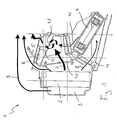
- an air conditioning system 1 a vehicle, in particular a passenger car, a cooling device 2 on, for example, by an evaporator in conventional Way is formed.
- a cooling device 2 Via an air supply channel 3 of the cooling device 2 unclimatized air, namely circulating air from the vehicle interior and / or fresh air from the vehicle environment supplied.
- the mixing ratio between fresh air and circulating air can usually be set become.
- the cooling device 2 the supplied fresh air / recirculated air cooled at the flow through the cooling device 2, so To produce cold air.
- the air conditioning system 1 also has a heater 4, the be formed for example by a heating medium / air heat exchanger can.
- This heater 4 is filled with air from the cooling device. 2 comes, charged. Accordingly, the heater 4 is activated Cooling device 2 with cold air and deactivated cooling device 2 with Circulating air / fresh air applied. When activated heater 4, the supplied Air heated or heated when flowing through the heating device 4, to generate hot air or warm air.
- the air conditioning system 1 comprises a hot air duct 41, which in Fig. 1 only is symbolized by an arrow and downstream of the heater. 4 starts. Flaps 42 specify how much cold air of the heating device 4 is supplied and heated at the flow therethrough.
- One of the Heating device 4 supplied cold air flow is shown in Fig. 1 by a with. 8 symbolized arrow symbolizes.
- the heater 4 immediate Cold air flow 7 and a in the flow through the heater 4 are generated and supplied via the hot air duct 41 hot air flow mixed in a mixing chamber 43 and thus form a heated air flow, the symbolized via an in Fig. 1 by an arrow hot air duct. 5 is dissipated.
- With the heated air from the hot air duct 5 usually a footwell and / or Defrostdüsen supplied.
- a water-side controlled system wherein the heating device 4 supplied via a valve with more or less (hot) coolant becomes.
- the cold air 7 or 8 then occurs after the evaporator 2 always by the heater 4 to produce the more or less heated air, which is removed via the hot air duct 5.
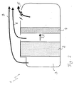
- a cold air duct 6 is provided, which in Figs. 1 and 2 also only symbolized by an arrow, the downstream of the cooling device 2, however starts upstream of the heater 4 and the heater 4 bypasses.
- the temperature can be individually cool and temper the air blown out at the nozzles.
- the nozzle air streams e.g. sitting in the dashboard may be cooler than the footwell. This is called layering and leads to more comfort.
- a fresh air / recirculating air channel 9 can be provided, the upstream of the cooling device 2 and also by an arrow is symbolized.
- the fresh air / recirculating air channel 9 bypasses the cooling device 2 and the heater 4. Accordingly, by the circulating air / fresh air duct transported unacclimated air.
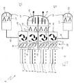
- FIGS. 3 and 4 said channels 5, 6 and 9 lead to one another a downstream mixing device 10 of the air conditioning system. 1 While in the embodiment shown in Fig. 3, only the warm air duct 5 and the cold air duct 6 shown and to the mixing device 10th are connected, Fig. 4 also shows the circulating air / fresh air duct 9, which is also connected to the mixing device 10 in this embodiment is.
- the air conditioning system 1 also has an outlet nozzle assembly 11, which in the present Case for both a driver's compartment 12 and a passenger compartment 13th each having a center nozzle 14 and a side nozzle 15 each. Accordingly If the outlet nozzles 14 and 15 are thus nozzles, which are assigned to a front area of the vehicle interior.
- the outlet nozzle assembly 11 may include nozzles, the one Rear area of the vehicle interior are assigned.
- the center nozzles 14 and the side nozzles 15 are useful in a dashboard of the vehicle. Likewise, embodiments are possible, in which center nozzles 14 arranged in the region of a center console are. Side nozzles 15 may also be used, for example, in side columns, e.g. in A-pillars, B-pillars or C-pillars, the vehicle or in the vehicle doors be arranged. Furthermore, in the footwell such To be arranged 14,15 nozzles. Likewise, the outlet nozzle arrangement 11 outlet nozzles 14,15 have that for deicing a windshield serve and along a lower edge of this windshield arranged in the dashboard. The side nozzles 15 are in the range the vehicle sides, so arranged in the vicinity lateral vehicle window. In contrast, the center nozzles 14 are approximately in the middle of the vehicle interior, so arranged relatively far away from the side windows.
- the side nozzle area in winter on the hot air of the hot air duct 5 without mixing cold air raise the cold air duct 6 in terms of discharge temperature, during the Center nozzle area blown out by cold air mixing cooler air.
- This is especially advantageous for cold doors.
- it may be in the Summer may be comfortable, e.g. when the sun is sideways it occurs to blow out 15 cooler air at the side jets.
- the Compensation of solar radiation is a decisive advantage of Invention.
- the mixing device 10 has at least for the central nozzles shown here 14 and side nozzles 15 each have a separate mixing space, namely for each center nozzle 14 has a central nozzle mixing chamber 16 and for each side nozzle 15 is a side nozzle mixing chamber 17.
- Each of these mixing chambers 16 and 17 is in each case connected to the hot air duct 5 and to the cold air duct 6.
- each mixing chamber is 16 and 17 each in addition to the circulating air / fresh air channel. 9 connected.
- the mixing chambers 16 and 17 are each on a mixed air duct 18 connected to the this mixing room 16,17 associated nozzle 14,15 leads. Apart from the side nozzle mixing rooms 17 of the embodiment of FIG.
- the mixing chambers 16 and 17 are each assigned a setting device 19, in FIGS. 3 and 4 respectively by pivotable control flaps 20th symbolically indicated.
- Each control flap 20 is one of the channels 5,6 and 9 assigned.
- the adjustment means 19 can for each mixing chamber 16,17 independent of the other mixing rooms 16,17 the mixing ratio of supplied cold air and supplied hot air and in the embodiment of FIG. 4 in addition to the supplied circulating air / fresh air be set.
- the mixing ratio can by corresponding actuations of the control flaps 20 can be set.
- the adjustment means 19 in principle instead of the control flaps 20 may contain any other suitable actuators with which the mixing ratio of the supplied air streams is adjustable. For example can use two or more channels with the help of a rotary valve be controlled simultaneously.
- the flaps 20 of side and middle nozzles can also be combined to a single flap, as well as the throttle 21 from a side and center nozzle.
- the adjustment 19 of the individual mixing chambers 16 and 17 are operated independently can, so that in the extreme case to the four nozzles 14 and 15 shown here For example, four different air flows are adjustable differ from each other by their temperature.
- each nozzle contains 14, 15 in an outflow area of it connected mixed air duct 18 each have a throttle device 21, with which the volume flow at the respective nozzle 14,15 is adjustable.
- these throttle devices 21 are independent of each other actuated, so that at the four nozzles shown here 14,15 each other Volume flows are adjustable.
- the two center nozzle mixing chambers 16 arranged in a common housing 22.
- the side nozzle mixing rooms 17 are each arranged in separate housing 23. at According to this embodiment, the mixture formation takes place immediately in front of the respective nozzle 14 and 15, respectively.
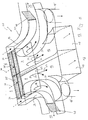
- both central nozzle mixing chambers 16 and both Side nozzle mixing chambers 17 housed in a common housing 24, whereby a mixer unit 25 is formed, which is shown here four independent mixing rooms 16,17 includes.
- the mixture formation takes place centrally in the mixer unit 25, whereby the effort for Supplying the side jets 15 is reduced with the conditioned air because only only the separate individual mixed air ducts 18 are laid have to.
- the individual mixing chambers 16 and 17 are each separate Branches connected to the channels 5,6,9. It is clear that the mixer unit 25 in a development a cold air plenum, a H thoroughly Kunststoffsammeiraum and optionally a recirculation / fresh air collection room may have, each of these plenums on the input side to the associated channel 5,6,9 is connected and the output side with the individual Mixed rooms 16 and 17 is connected.
- the cable routing can be simplified by such a construction.
- the nozzles 14,15 from the driver side 12 and passenger side 13 basically independent of each other in terms of the mixing ratio are variable. It is clear that the driver or the Passenger each additional additional manianahe nozzles 15 and / or windows distant nozzles 14 may be associated with these additional In principle, nozzles can also have separate mixing chambers and in terms of their mixing ratio, independent of the others Nozzles can be adjustable. However, a construction method is preferred the several near-window side nozzles 15, e.g. one in the dashboard and one in the B-pillar, a common side nozzle mixing chamber 17 have.
- the coupled via the common side nozzle mixing chamber 17 with each other Side nozzles 15 receive accordingly over the mixed air channels the same conditioned air.
- a plurality of remote center nozzles 14, e.g. one in the dashboard and one in the center console, are provided.
- These central nozzles 14 can one have common central jet mixing chamber 16 and are accordingly supplied with the same conditioned air.
- the air conditioning system 1 with a by a Frame symbolized control device 26 may be equipped, the via control lines 27 with the adjustment 19 of the mixing chambers 16,17 is connected.
- the adjusting devices 19 have corresponding, not shown here, actuators by the controller 26 can be actuated via the control lines 27.
- the control device 26 is also shown with an example only Sensor 28 connected, for example, via at least one thermopile sensor 29, or at least one sunlight sensor 30 or at least a conventional temperature sensor 31 or a combination of several various sensors 29,30,31 includes.
- the control device 26 may for example be designed so that in dependence of predetermined or specifiable conditions, the mixing ratios in the central jet mixing compartments 16 and in the side jet mixing compartments 17 automatically.
- the actuation of the Adjustment means 19 in the sense of control e.g. with the help of maps, or in the sense of a regulation, e.g. with a target-actual comparison of Temperature values, done.
- the surface temperature of the driver or the passenger Various locations are measured using the outlet nozzles 14,15 are acted upon. Depending on the measurement results can then the mixing ratios for the outlet nozzles 14,15 on the current Surface temperatures are tuned.
- the current sunlight irradiation situation in the vehicle interior or at the respective seats be recorded and evaluated.
- the mixing ratios can then in a suitable manner to the current sunlight irradiation situation be adjusted.
- the controller 26 then actuates the adjustment means 19 in a suitable manner to a desired temperature distribution to reach in the vehicle interior.
- the control device 26 optimized especially with regard to the following requirements
- the energy consumption to achieve a desired temperature distribution should be minimized. To achieve the desired Temperature distribution required flow rates be minimized. Furthermore, they are intended to achieve the desired Temperature distribution required volume flows are minimized. A total of This results in an increased comfort in the air conditioning of Vehicle interior.
- the mixer unit 25 in its housing 24 for the driver side 12 and for the passenger side 13 contain the two center nozzle mixing chambers 16, the output side go over into the associated mixed air channels 18.
- On the input side is each center nozzle mixing chamber 16 arranged on a bottom side Opening 32 connected to the hot air duct 5, so that through the opening 32 according to arrows 33 hot air flows into the central nozzle mixing chambers 16.
- the central nozzle mixing chambers 16 are frontally over Inlet openings 34 connected to the cold air duct 6, wherein in the inlet openings 34 each have a control flap 35 is arranged, with the Opening cross section of the associated inlet opening 34 is adjustable.
- Corresponding Arrows 36 can then cold air into the central nozzle mixing chambers 16th flow.
- Fig. 5 is by means of a Partition wall 37 a part of the bottom-side opening 32 in the respective central jet mixing chamber 16 hidden, so that part of the hot air duct 5 supplied tempered air according to an arrow 38 to the side nozzle mixing chamber 17 of the respective side nozzle 15 passes.
- the side nozzle mixing rooms 17 form the inlet sections of the side nozzles 15 leading mixed air channels 18.
- the side nozzle mixing chambers 17 are also connected via a channel section 39 to the cold air duct 6.
- a control flap 40 arranged, with the help of which the mixing ratio between Hot air inlet and cold air inlet in the side nozzle mixing chambers 17 adjustable is.
Landscapes
- Physics & Mathematics (AREA)
- Thermal Sciences (AREA)
- Engineering & Computer Science (AREA)
- Mechanical Engineering (AREA)
- Air-Conditioning For Vehicles (AREA)
- Sorption Type Refrigeration Machines (AREA)
Abstract
Description
- Fig. 1
- eine stark vereinfachte Schnittansicht durch einen Teil einer Klimatisierungsanlage nach der Erfindung,
- Fig. 2
- eine Ansicht wie in Fig. 1, jedoch einer anderen Ausführungsform,
- Fig. 3
- eine schaltplanartige Prinzipdarstellung eines anderen Teils der Klimatisierungsanlage bei einer ersten Ausführungsform,
- Fig. 4
- eine Darstellung wie in Fig. 3, jedoch bei einer zweiten Ausführungsform, und
- Fig. 5
- eine perspektivische, stark vereinfachte Darstellung einer Mischereinheit bei einer besonderen Ausführungsform.
- 1
- Klimatisierungsanlage
- 2
- Kühleinrichtung
- 3
- Luftzuführungskanal
- 4
- Heizeinrichtung
- 5
- Warmluftkanal
- 6
- Kaltluftkanal
- 7
- Kaltluftstrom
- 8
- Kaltluftzufuhr zu 4
- 9
- Umluft/Frischluftkanal
- 10
- Mischeinrichtung
- 11
- Austrittsdüsenanordnung
- 12
- Fahrerseite
- 13
- Beifahrerseite
- 14
- Mitteldüse
- 15
- Seitendüse
- 16
- Mitteldüsenmischraum
- 17
- Seitendüsenmischraum
- 18
- Mischluftkanal
- 19
- Einstelleinrichtung
- 20
- Steuerklappe
- 21
- Drosseleinrichtung
- 22
- Gehäuse
- 23
- Gehäuse
- 24
- Gehäuse
- 25
- Mischereinheit
- 26
- Steuerungseinrichtung
- 27
- Steuerleitung
- 28
- Sensorik
- 29
- Thermopilesensor
- 30
- Sonnenlichtsensor
- 31
- Temperatursensor
- 32
- Öffnung
- 33
- Strömungspfeil
- 34
- Eintrittsöffnung
- 35
- Steuerklappe
- 36
- Strömungspfeil
- 37
- Wand
- 38
- Strömungspfeil
- 39
- Kanalabschnitt
- 40
- Steuerklappe
- 41
- Heißluftkanal
- 42
- Klappe
- 43
- Mischraum
Claims (19)
- Klimatisierungsanlage eines Fahrzeugs, insbesondere eines Personenkraftwagens, zur Zuführung klimatisierter Luft in einen Fahrzeuginnenraum,mit einer Austrittsdüsenanordnung (11), die für wenigstens einen Sitzplatz im Fahrzeuginnenraum jeweils wenigstens eine fensterferne Mitteldüse (14) und wenigstens eine fensternahe Seitendüse (15) aufweist,mit einer Kühleinrichtung (2), die mit Frischluft und/oder Umluft beaufschlagt ist und zum Kühlen der zugeführten Luft dient,mit einer Heizeinrichtung (4), die mit von der Kühleinrichtung (2) kommender Luft beaufschlagt ist und zum Heizen der zugeführten Luft dient,mit einer Mischeinrichtung (10), die wenigstens einen Mischraum (16,17) aufweist, an den eingangsseitig ein von der Kühleinrichtung (2) kommender und die Heizeinrichtung (4) umgehender Kaltluftkanal (6) und ein von der Heizeinrichtung (4) kommender Warmluftkanal (5) angeschlossen sind und an den ausgangsseitig ein zu wenigstens einer Düse (14,15) führender Mischluftkanal (18) angeschlossen ist,wobei die Mischeinrichtung (10) für die Mitteldüse (14) einen Mitteldüsenmischraum (16) und für die Seitendüse (15) einen Seitendüsenmischraum (17) aufweist,wobei Mitteldüsenmischraum (16) und Seitendüsenmischraum (17) jeweils für sich an den Kaltluftkanal (6) und an den Warmluftkanal (5) angeschlossen sind,wobei der Mitteldüsenmischraum (16) und der Seitendüsenmischraum (17) jeweils über einen separaten Mischluftkanal (18) an die zugehörige Düse (14,15) angeschlossen sind.
- Klimatisierungsanlage nach Anspruch 1,
dadurch gekennzeichnet, daß Mitteldüsenmischraum (16) und Seitendüsenmischraum (17) in voneinander getrennten Gehäusen (22,23) angeordnet und/oder ausgebildet sind. - Klimatisierungsanlage nach Anspruch 1,
dadurch gekennzeichnet, daß Mitteldüsenmischraum (16) und Seitendüsenmischraum (17) in einem gemeinsamen Gehäuse (24) einer Mischereinheit (25) angeordnet und/oder ausgebildet sind. - Klimatisierungsanlage nach einem der Ansprüche 1 bis 3,
dadurch gekennzeichnet, daß der Mitteldüsenmischraum (16) und der Seitendüsenmischraum (17) jeweils durch den zugehörigen Mischluftkanal (18) oder durch einen Einströmabschnitt des zugehörigen Mischluftkanals (18) gebildet sind. - Klimatisierungsanlage nach einem der Ansprüche 1 bis 4,
dadurch gekennzeichnet, daß der Mitteldüsenmischraum (16) und der Seitendüsenmischraum (17) jeweils für sich eingangsseitig an einen die Kühleinrichtung (2) und die Heizeinrichtung (4) umgehenden Frischluft/Umluftkanal (9) angeschlossen sind. - Klimatisierungsanlage nach einem der Ansprüche 1 bis 5,
dadurch gekennzeichnet, daß beim Mitteldüsenmischraum (16) und beim Seitendüsenmischraum (17) jeweils ein Mischungsverhältnis von zugeführten Kaltluft und zugeführter Warmluft und gegebenenfalls zugeführter Frischluft/Umluft unabhängig vom anderen Mischraum (16,17) einstellbar ist. - Klimatisierungsanlage nach Anspruch 6,
dadurch gekennzeichnet, daß dem Mitteldüsenmischraum (16) und dem Seitendüsenmischraum (17) jeweils eine Einstelleinrichtung (19) zum Einstellen der zugeführten Kaltluftmenge und der zugeführten Warmluftmenge und gegebenenfalls der zugeführten Frischluft/Umluftmenge zugeordnet ist, wobei die Einstelleinrichtung (19) des Mitteldüsenraums (16) und die Einstelleinrichtung (19) des Seitendüsenmischraums (17) unabhängig voneinander betätigbar sind. - Klimatiserungsanlage nach einem der Ansprüche 1 bis 7,
dadurch gekennzeichnet, daß eine Wechselklappe vorgesehen ist, die Kaltluft in variablem Verhältnis den jedem Insassen zugeordneten Seitendüsen (15) und Mitteldüsen (14) zumischen kann. - Klimatisierungsanlage nach einem der Ansprüche 1 bis 8,
dadurch gekennzeichnet, daß eine Drossel-Wechselklappe vorgesehen ist, die Luft in variablen Mengenverhältnissen den jedem Insassen zugeordneten Seitendüsen (15) und Mitteldüsen (14) zuführen kann. - Klimatisierungsanlage nach einem der Ansprüche 1 bis 9,
dadurch gekennzeichnet, daß die Seitendüse (15) zumindest eines Insassen und die Mitteldüse (14) des neben ihm sitzenden Insassen an den gleichen Kaltluftkanal (6) angeschlossen sind, wobei diesen Düsen (14,15) gemeinsam über eine gemeinsame Mischklappe die Kaltluft zugemischt wird. - Klimatisierungsanlage nach einem der Ansprüche 1 bis 10,
dadurch gekennzeichnet, daß die Seitendüse (15) zumindest eines Insassen und die Mitteldüse (14) des neben ihm sitzenden Insassen gemeinsam an den Warmluftkanal (5) angeschlossen sind und gemeinsam von einer gemeinsamen Drosselklappe abgedrosselt werden. - Klimatisierungsanlage nach einem der Ansprüche 1 bis 11,
dadurch gekennzeichnet,daß die Austrittsdüsenanordnung (11) im Frontbereich und/oder im Fondbereich des Fahrzeuginnenraums sowohl für die Fahrerseite (12) als auch für die Beifahrerseite (13) jeweils wenigstens eine fensterferne Mitteldüse (14) mit zugehörigem Mitteldüsenmischraum (16) und wenigstens eine fensternahe Seitendüse (15) mit zugehörigem Seitendüsenmischraum (17) aufweist,wobei bei den Mischräumen (16,17) der Fahrerseite (12) und bei den Mischräumen (16,17) der Beifahrerseite (13) jeweils das Mischungsverhältnis von zugeführter Kaltluft und zugeführter Warmluft und gegebenenfalls zugeführter Frischluft/Umluft unabhängig von den Mischräumen (16,17) der anderen Fahrzeugseite (12,13) einstellbar ist und/oderwobei bei den Mischräumen (16,17) des Frontbereichs und bei den Mischräumen (16,17) des Fondbereichs jeweils das Mischungsverhältnis von zugeführter Kaltluft und zugeführter Heißluft und gegebenenfalls zugeführter Frischluft/Umluft unabhängig von den Mischräumen (16,17) des anderen Innenraumbereichs einstellbar ist. - Klimatisierungsanlage zumindest nach Anspruch 6 oder 7,
dadurch gekennzeichnet, daß eine Steuerungseinrichtung (26) vorgesehen ist, die in Abhängigkeit vorgegebener und/oder vorgebbarer Bedingungen die Mischungsverhältnisse im Mitteldüsenmischraum (16) und im Seitendüsenmischraum (17) automatisch einstellt. - Klimatisierungsanlage nach Anspruch 13,
dadurch gekennzeichnet, daß die Bedingungen eine Oberflächentemperatur der auf dem zugehörigen Sitzplatz sitzenden Person und/oder eine Sonnenlichteinstrahlungssituation und/oder Temperaturwerte an wenigstens einer vorbestimmten Temperaturmeßstelle und/oder vorgebbare Sollwerttemperaturen umfassen. - Klimatisierungsanlage nach Anspruch 13 oder 14,
dadurch gekennzeichnet, daß die Steuerungseinrichtung (26) mit einer Sensorik (28) verbunden ist, die wenigstens einen Thermopilesensor (29) und/oder wenigstens einen Sonnenlichtsensor (30) und/oder wenigstens einen Temperatursensor (31) umfaßt. - Klimatisierungsanlage nach einem der Ansprüche 1 bis 15,
dadurch gekennzeichnet, daß wenigstens eine der Seitendüsen (15) im Armaturenbrett angeordnet ist und/oder daß wenigstens eine der Seitendüsen (15) in einer Seitensäule des Fahrzeugs angeordnet ist und/oder daß wenigstens eine der Seitendüsen (15) in einer Seitentür angeordnet ist und/oder daß wenigstens eine der Seitendüsen (15) im Fußraum des Fahrzeugs angeordnet ist. - Klimatisierungsanlage nach einem der Ansprüche 1 bis 16,
dadurch gekennzeichnet, daß mehrere Seitendüsen (15) vorgesehen sind, die an einen gemeinsamen Seitendüsenmischraum (17) angeschlossen sind. - Klimatisierungsanlage nach einem der Ansprüche 1 bis 17,
dadurch gekennzeichnet, daß wenigstens eine der Mitteldüsen (14) im Armaturenbrett angeordnet ist und/oder daß wenigstens eine der Mitteldüsen (14) in einer Mittelkonsole des Fahrzeugs angeordnet ist und/oder daß wenigstens eine Mitteldüsen (14) im Fußraum des Fahrzeugs angeordnet ist. - Klimatisierungsanlage nach einem der Ansprüche 1 bis 18,
dadurch gekennzeichnet, daß mehrere Mitteldüsen (14) vorgesehen sind, die an einen gemeinsamen Mitteldüsenraum (16) angeschlossen sind.
Applications Claiming Priority (2)
| Application Number | Priority Date | Filing Date | Title |
|---|---|---|---|
| DE10200487 | 2002-01-09 | ||
| DE10200487A DE10200487A1 (de) | 2002-01-09 | 2002-01-09 | Klimatisierungsanlage eines Fahrzeugs |
Publications (2)
| Publication Number | Publication Date |
|---|---|
| EP1327541A1 true EP1327541A1 (de) | 2003-07-16 |
| EP1327541B1 EP1327541B1 (de) | 2006-11-22 |
Family
ID=7711707
Family Applications (1)
| Application Number | Title | Priority Date | Filing Date |
|---|---|---|---|
| EP02027539A Expired - Lifetime EP1327541B1 (de) | 2002-01-09 | 2002-12-09 | Klimatisierungsanlage eines Fahrzeugs |
Country Status (3)
| Country | Link |
|---|---|
| EP (1) | EP1327541B1 (de) |
| AT (1) | ATE345940T1 (de) |
| DE (2) | DE10200487A1 (de) |
Cited By (1)
| Publication number | Priority date | Publication date | Assignee | Title |
|---|---|---|---|---|
| EP1972473A1 (de) * | 2007-03-23 | 2008-09-24 | Behr GmbH & Co. KG | Klimaanlage für ein Kraftfahrzeug |
Families Citing this family (1)
| Publication number | Priority date | Publication date | Assignee | Title |
|---|---|---|---|---|
| DE102010029807A1 (de) * | 2010-06-08 | 2011-12-08 | Behr Gmbh & Co. Kg | Kraftfahrzeugklimatisierung mit dezentralem Luftverteilungssystem |
Citations (4)
| Publication number | Priority date | Publication date | Assignee | Title |
|---|---|---|---|---|
| DE1001907B (de) * | 1953-07-02 | 1957-01-31 | Daimler Benz Ag | Lueftungs- und Heizungsanordnung fuer Kraftfahrzeuge |
| DE1942938A1 (de) * | 1969-08-23 | 1971-03-11 | Sueddeutsche Kuehler Behr | Klimaanlage fuer Kraftfahrzeuge |
| JPS5551615A (en) * | 1978-10-06 | 1980-04-15 | Mitsubishi Motors Corp | Air conditioner for vehicle |
| JPH01247210A (ja) * | 1988-03-30 | 1989-10-03 | Nissan Shatai Co Ltd | 自動車用空調装置のヒータユニット構造 |
Family Cites Families (5)
| Publication number | Priority date | Publication date | Assignee | Title |
|---|---|---|---|---|
| DE3911616C3 (de) * | 1989-04-08 | 1997-04-03 | Audi Ag | Heiz- oder Klimaanlage für den Fahrgastraum von Kraftfahrzeugen |
| DE3940361A1 (de) * | 1989-12-06 | 1991-06-13 | Bayerische Motoren Werke Ag | Heizungs- und/oder klimaanlage fuer kraftfahrzeuginnenraeume |
| JP2690803B2 (ja) * | 1990-04-24 | 1997-12-17 | 株式会社デンソー | 空調制御装置 |
| DE19706948C1 (de) * | 1997-02-21 | 1998-04-09 | Daimler Benz Ag | Heizungs- oder Klimaanlage |
| DE19739578C2 (de) * | 1997-09-10 | 2000-03-02 | Behr Gmbh & Co | Heizungs- oder Klimaanlage für ein Kraftfahrzeug |
-
2002
- 2002-01-09 DE DE10200487A patent/DE10200487A1/de not_active Withdrawn
- 2002-12-09 DE DE50208770T patent/DE50208770D1/de not_active Expired - Lifetime
- 2002-12-09 EP EP02027539A patent/EP1327541B1/de not_active Expired - Lifetime
- 2002-12-09 AT AT02027539T patent/ATE345940T1/de not_active IP Right Cessation
Patent Citations (4)
| Publication number | Priority date | Publication date | Assignee | Title |
|---|---|---|---|---|
| DE1001907B (de) * | 1953-07-02 | 1957-01-31 | Daimler Benz Ag | Lueftungs- und Heizungsanordnung fuer Kraftfahrzeuge |
| DE1942938A1 (de) * | 1969-08-23 | 1971-03-11 | Sueddeutsche Kuehler Behr | Klimaanlage fuer Kraftfahrzeuge |
| JPS5551615A (en) * | 1978-10-06 | 1980-04-15 | Mitsubishi Motors Corp | Air conditioner for vehicle |
| JPH01247210A (ja) * | 1988-03-30 | 1989-10-03 | Nissan Shatai Co Ltd | 自動車用空調装置のヒータユニット構造 |
Non-Patent Citations (2)
| Title |
|---|
| PATENT ABSTRACTS OF JAPAN vol. 004, no. 094 (M - 019) 8 July 1980 (1980-07-08) * |
| PATENT ABSTRACTS OF JAPAN vol. 013, no. 588 (M - 912) 25 December 1989 (1989-12-25) * |
Cited By (1)
| Publication number | Priority date | Publication date | Assignee | Title |
|---|---|---|---|---|
| EP1972473A1 (de) * | 2007-03-23 | 2008-09-24 | Behr GmbH & Co. KG | Klimaanlage für ein Kraftfahrzeug |
Also Published As
| Publication number | Publication date |
|---|---|
| ATE345940T1 (de) | 2006-12-15 |
| EP1327541B1 (de) | 2006-11-22 |
| DE50208770D1 (de) | 2007-01-04 |
| DE10200487A1 (de) | 2003-07-10 |
Similar Documents
| Publication | Publication Date | Title |
|---|---|---|
| DE102008034167A1 (de) | Klimaanlage für Fahrzeuge | |
| DE19534078B4 (de) | Kraftfahrzeug-Klimaanlage | |
| EP1607254B1 (de) | Vorrichtung zur Luftzuführung in einen Innenraum eines Fahrzeuges | |
| EP0805056A2 (de) | Fahrzeugklimatisierungseinrichtung mit sonneneinstrahlungsabhängig verstellbarer Luftleitvorrichtung | |
| DE102011077339A1 (de) | Vorrichtung und Verfahren zur Elektrikraumkühlung | |
| EP1708900A1 (de) | Verfahren zur regelung von luftdüsen zur klimatisierung eines kraftfahrzeugs | |
| EP0893292A2 (de) | Heizungs- oder Klimaanlage für ein Kraftfahrzeug | |
| DE19910351A1 (de) | Fahrzeug-Klimatisierungssystem mit unabhängiger Temperaturregelung zwischen links und rechts während des maximalen Kühlens | |
| DE10037384A1 (de) | Heizungs- und Klimaanlage für ein Kraftfahrzeug | |
| DE102004033402B4 (de) | Modulsystem zum Aufbau einer 1-Zonen-bis 4-Zonen-Klimaanlage für Fahrzeuge | |
| DE7731774U1 (de) | Klimatisiertes Personenkraftfahrzeug, vorzugsweise mit einer Trennwand zwischen dem vorderen Teil der Fahrgastzelle und dem Fondraum | |
| DE102019220154A1 (de) | Klimaanlage | |
| DE19539001B4 (de) | Klimaanlage | |
| DE102021208599A1 (de) | Verfahren zum Steuern eines Fahrzeug-HVAC-Systems | |
| DE10015972A1 (de) | Klimaanlage für ein Kraftfahrzeug | |
| EP1205321A2 (de) | Klima- und Belüftungsanlage für ein Kraftfahrzeug | |
| DE10016433A1 (de) | Klimaanlage für ein Kraftfahrzeug | |
| DE2742670C2 (de) | ||
| DE102014210264A1 (de) | Klimaanlage und Verfahren zur Lufttemperierung | |
| DE10037066A1 (de) | Fahrzeugklimatisierungseinrichtung | |
| DE4143101C2 (de) | Klimaanlage für ein Kraftfahrzeug | |
| DE102008030063A1 (de) | Klimaanlage | |
| EP1327541B1 (de) | Klimatisierungsanlage eines Fahrzeugs | |
| DE102020110843A1 (de) | System zum Temperieren einer Fahrgastzelle mit einem Luftstrom | |
| DE19948735A1 (de) | Verfahren und Einrichtung zur Klimatisierung von Fahrzeugsitzen |
Legal Events
| Date | Code | Title | Description |
|---|---|---|---|
| PUAI | Public reference made under article 153(3) epc to a published international application that has entered the european phase |
Free format text: ORIGINAL CODE: 0009012 |
|
| AK | Designated contracting states |
Designated state(s): AT BE BG CH CY CZ DE DK EE ES FI FR GB GR IE IT LI LU MC NL PT SE SI SK TR |
|
| AX | Request for extension of the european patent |
Extension state: AL LT LV MK RO |
|
| 17P | Request for examination filed |
Effective date: 20030829 |
|
| 17Q | First examination report despatched |
Effective date: 20040212 |
|
| AKX | Designation fees paid |
Designated state(s): AT BE BG CH CY CZ DE DK EE ES FI FR GB GR IE IT LI LU MC NL PT SE SI SK TR |
|
| AXX | Extension fees paid |
Extension state: AL Payment date: 20040116 Extension state: MK Payment date: 20040116 Extension state: RO Payment date: 20040116 Extension state: LV Payment date: 20040116 Extension state: LT Payment date: 20040116 |
|
| DAX | Request for extension of the european patent (deleted) | ||
| RAP1 | Party data changed (applicant data changed or rights of an application transferred) |
Owner name: BEHR GMBH & CO. KG |
|
| GRAC | Information related to communication of intention to grant a patent modified |
Free format text: ORIGINAL CODE: EPIDOSCIGR1 |
|
| GRAP | Despatch of communication of intention to grant a patent |
Free format text: ORIGINAL CODE: EPIDOSNIGR1 |
|
| GRAS | Grant fee paid |
Free format text: ORIGINAL CODE: EPIDOSNIGR3 |
|
| GRAA | (expected) grant |
Free format text: ORIGINAL CODE: 0009210 |
|
| AK | Designated contracting states |
Kind code of ref document: B1 Designated state(s): AT BE BG CH CY CZ DE DK EE ES FI FR GB GR IE IT LI LU MC NL PT SE SI SK TR |
|
| PG25 | Lapsed in a contracting state [announced via postgrant information from national office to epo] |
Ref country code: IT Free format text: LAPSE BECAUSE OF FAILURE TO SUBMIT A TRANSLATION OF THE DESCRIPTION OR TO PAY THE FEE WITHIN THE PRESCRIBED TIME-LIMIT;WARNING: LAPSES OF ITALIAN PATENTS WITH EFFECTIVE DATE BEFORE 2007 MAY HAVE OCCURRED AT ANY TIME BEFORE 2007. THE CORRECT EFFECTIVE DATE MAY BE DIFFERENT FROM THE ONE RECORDED. Effective date: 20061122 Ref country code: SK Free format text: LAPSE BECAUSE OF FAILURE TO SUBMIT A TRANSLATION OF THE DESCRIPTION OR TO PAY THE FEE WITHIN THE PRESCRIBED TIME-LIMIT Effective date: 20061122 Ref country code: NL Free format text: LAPSE BECAUSE OF FAILURE TO SUBMIT A TRANSLATION OF THE DESCRIPTION OR TO PAY THE FEE WITHIN THE PRESCRIBED TIME-LIMIT Effective date: 20061122 Ref country code: SI Free format text: LAPSE BECAUSE OF FAILURE TO SUBMIT A TRANSLATION OF THE DESCRIPTION OR TO PAY THE FEE WITHIN THE PRESCRIBED TIME-LIMIT Effective date: 20061122 Ref country code: CZ Free format text: LAPSE BECAUSE OF FAILURE TO SUBMIT A TRANSLATION OF THE DESCRIPTION OR TO PAY THE FEE WITHIN THE PRESCRIBED TIME-LIMIT Effective date: 20061122 Ref country code: IE Free format text: LAPSE BECAUSE OF FAILURE TO SUBMIT A TRANSLATION OF THE DESCRIPTION OR TO PAY THE FEE WITHIN THE PRESCRIBED TIME-LIMIT Effective date: 20061122 Ref country code: FI Free format text: LAPSE BECAUSE OF FAILURE TO SUBMIT A TRANSLATION OF THE DESCRIPTION OR TO PAY THE FEE WITHIN THE PRESCRIBED TIME-LIMIT Effective date: 20061122 |
|
| REG | Reference to a national code |
Ref country code: GB Ref legal event code: FG4D Free format text: NOT ENGLISH |
|
| REG | Reference to a national code |
Ref country code: CH Ref legal event code: EP |
|
| REG | Reference to a national code |
Ref country code: IE Ref legal event code: FG4D Free format text: LANGUAGE OF EP DOCUMENT: GERMAN |
|
| PG25 | Lapsed in a contracting state [announced via postgrant information from national office to epo] |
Ref country code: MC Free format text: LAPSE BECAUSE OF NON-PAYMENT OF DUE FEES Effective date: 20061231 Ref country code: LI Free format text: LAPSE BECAUSE OF NON-PAYMENT OF DUE FEES Effective date: 20061231 Ref country code: CH Free format text: LAPSE BECAUSE OF NON-PAYMENT OF DUE FEES Effective date: 20061231 Ref country code: BE Free format text: LAPSE BECAUSE OF NON-PAYMENT OF DUE FEES Effective date: 20061231 |
|
| REF | Corresponds to: |
Ref document number: 50208770 Country of ref document: DE Date of ref document: 20070104 Kind code of ref document: P |
|
| PG25 | Lapsed in a contracting state [announced via postgrant information from national office to epo] |
Ref country code: DK Free format text: LAPSE BECAUSE OF FAILURE TO SUBMIT A TRANSLATION OF THE DESCRIPTION OR TO PAY THE FEE WITHIN THE PRESCRIBED TIME-LIMIT Effective date: 20070222 Ref country code: BG Free format text: LAPSE BECAUSE OF FAILURE TO SUBMIT A TRANSLATION OF THE DESCRIPTION OR TO PAY THE FEE WITHIN THE PRESCRIBED TIME-LIMIT Effective date: 20070222 Ref country code: SE Free format text: LAPSE BECAUSE OF FAILURE TO SUBMIT A TRANSLATION OF THE DESCRIPTION OR TO PAY THE FEE WITHIN THE PRESCRIBED TIME-LIMIT Effective date: 20070222 |
|
| PG25 | Lapsed in a contracting state [announced via postgrant information from national office to epo] |
Ref country code: ES Free format text: LAPSE BECAUSE OF FAILURE TO SUBMIT A TRANSLATION OF THE DESCRIPTION OR TO PAY THE FEE WITHIN THE PRESCRIBED TIME-LIMIT Effective date: 20070305 |
|
| PG25 | Lapsed in a contracting state [announced via postgrant information from national office to epo] |
Ref country code: PT Free format text: LAPSE BECAUSE OF FAILURE TO SUBMIT A TRANSLATION OF THE DESCRIPTION OR TO PAY THE FEE WITHIN THE PRESCRIBED TIME-LIMIT Effective date: 20070423 |
|
| NLV1 | Nl: lapsed or annulled due to failure to fulfill the requirements of art. 29p and 29m of the patents act | ||
| ET | Fr: translation filed | ||
| GBV | Gb: ep patent (uk) treated as always having been void in accordance with gb section 77(7)/1977 [no translation filed] |
Effective date: 20061122 |
|
| REG | Reference to a national code |
Ref country code: IE Ref legal event code: FD4D |
|
| REG | Reference to a national code |
Ref country code: CH Ref legal event code: PL |
|
| PLBE | No opposition filed within time limit |
Free format text: ORIGINAL CODE: 0009261 |
|
| STAA | Information on the status of an ep patent application or granted ep patent |
Free format text: STATUS: NO OPPOSITION FILED WITHIN TIME LIMIT |
|
| 26N | No opposition filed |
Effective date: 20070823 |
|
| PG25 | Lapsed in a contracting state [announced via postgrant information from national office to epo] |
Ref country code: GB Free format text: LAPSE BECAUSE OF FAILURE TO SUBMIT A TRANSLATION OF THE DESCRIPTION OR TO PAY THE FEE WITHIN THE PRESCRIBED TIME-LIMIT Effective date: 20061122 |
|
| BERE | Be: lapsed |
Owner name: BEHR G.M.B.H. & CO. KG Effective date: 20061231 |
|
| PG25 | Lapsed in a contracting state [announced via postgrant information from national office to epo] |
Ref country code: AT Free format text: LAPSE BECAUSE OF NON-PAYMENT OF DUE FEES Effective date: 20061209 |
|
| PG25 | Lapsed in a contracting state [announced via postgrant information from national office to epo] |
Ref country code: GR Free format text: LAPSE BECAUSE OF FAILURE TO SUBMIT A TRANSLATION OF THE DESCRIPTION OR TO PAY THE FEE WITHIN THE PRESCRIBED TIME-LIMIT Effective date: 20070223 |
|
| PG25 | Lapsed in a contracting state [announced via postgrant information from national office to epo] |
Ref country code: EE Free format text: LAPSE BECAUSE OF FAILURE TO SUBMIT A TRANSLATION OF THE DESCRIPTION OR TO PAY THE FEE WITHIN THE PRESCRIBED TIME-LIMIT Effective date: 20061122 |
|
| PG25 | Lapsed in a contracting state [announced via postgrant information from national office to epo] |
Ref country code: TR Free format text: LAPSE BECAUSE OF FAILURE TO SUBMIT A TRANSLATION OF THE DESCRIPTION OR TO PAY THE FEE WITHIN THE PRESCRIBED TIME-LIMIT Effective date: 20061122 Ref country code: LU Free format text: LAPSE BECAUSE OF NON-PAYMENT OF DUE FEES Effective date: 20061209 |
|
| PG25 | Lapsed in a contracting state [announced via postgrant information from national office to epo] |
Ref country code: CY Free format text: LAPSE BECAUSE OF FAILURE TO SUBMIT A TRANSLATION OF THE DESCRIPTION OR TO PAY THE FEE WITHIN THE PRESCRIBED TIME-LIMIT Effective date: 20061122 |
|
| PGFP | Annual fee paid to national office [announced via postgrant information from national office to epo] |
Ref country code: FR Payment date: 20100106 Year of fee payment: 8 |
|
| REG | Reference to a national code |
Ref country code: FR Ref legal event code: ST Effective date: 20110831 |
|
| PG25 | Lapsed in a contracting state [announced via postgrant information from national office to epo] |
Ref country code: FR Free format text: LAPSE BECAUSE OF NON-PAYMENT OF DUE FEES Effective date: 20110103 |
|
| REG | Reference to a national code |
Ref country code: DE Ref legal event code: R082 Ref document number: 50208770 Country of ref document: DE Representative=s name: GRAUEL, ANDREAS, DIPL.-PHYS. DR. RER. NAT., DE |
|
| REG | Reference to a national code |
Ref country code: DE Ref legal event code: R082 Ref document number: 50208770 Country of ref document: DE Representative=s name: GRAUEL, ANDREAS, DIPL.-PHYS. DR. RER. NAT., DE Effective date: 20150310 Ref country code: DE Ref legal event code: R081 Ref document number: 50208770 Country of ref document: DE Owner name: MAHLE INTERNATIONAL GMBH, DE Free format text: FORMER OWNER: BEHR GMBH & CO. KG, 70469 STUTTGART, DE Effective date: 20150310 |
|
| PGFP | Annual fee paid to national office [announced via postgrant information from national office to epo] |
Ref country code: DE Payment date: 20190109 Year of fee payment: 17 |
|
| REG | Reference to a national code |
Ref country code: DE Ref legal event code: R119 Ref document number: 50208770 Country of ref document: DE |
|
| PG25 | Lapsed in a contracting state [announced via postgrant information from national office to epo] |
Ref country code: DE Free format text: LAPSE BECAUSE OF NON-PAYMENT OF DUE FEES Effective date: 20200701 |