EP1325833A2 - Hydrostatischer Fahrantrieb - Google Patents
Hydrostatischer Fahrantrieb Download PDFInfo
- Publication number
- EP1325833A2 EP1325833A2 EP03006245A EP03006245A EP1325833A2 EP 1325833 A2 EP1325833 A2 EP 1325833A2 EP 03006245 A EP03006245 A EP 03006245A EP 03006245 A EP03006245 A EP 03006245A EP 1325833 A2 EP1325833 A2 EP 1325833A2
- Authority
- EP
- European Patent Office
- Prior art keywords
- hydraulic
- vehicle
- hydraulic motor
- control valve
- control
- Prior art date
- Legal status (The legal status is an assumption and is not a legal conclusion. Google has not performed a legal analysis and makes no representation as to the accuracy of the status listed.)
- Granted
Links
Images


Classifications
-
- F—MECHANICAL ENGINEERING; LIGHTING; HEATING; WEAPONS; BLASTING
- F16—ENGINEERING ELEMENTS AND UNITS; GENERAL MEASURES FOR PRODUCING AND MAINTAINING EFFECTIVE FUNCTIONING OF MACHINES OR INSTALLATIONS; THERMAL INSULATION IN GENERAL
- F16H—GEARING
- F16H61/00—Control functions within control units of change-speed- or reversing-gearings for conveying rotary motion ; Control of exclusively fluid gearing, friction gearing, gearings with endless flexible members or other particular types of gearing
- F16H61/38—Control of exclusively fluid gearing
- F16H61/40—Control of exclusively fluid gearing hydrostatic
- F16H61/4148—Open loop circuits
-
- F—MECHANICAL ENGINEERING; LIGHTING; HEATING; WEAPONS; BLASTING
- F16—ENGINEERING ELEMENTS AND UNITS; GENERAL MEASURES FOR PRODUCING AND MAINTAINING EFFECTIVE FUNCTIONING OF MACHINES OR INSTALLATIONS; THERMAL INSULATION IN GENERAL
- F16H—GEARING
- F16H39/00—Rotary fluid gearing using pumps and motors of the volumetric type, i.e. passing a predetermined volume of fluid per revolution
- F16H39/02—Rotary fluid gearing using pumps and motors of the volumetric type, i.e. passing a predetermined volume of fluid per revolution with liquid motors at a distance from liquid pumps
-
- F—MECHANICAL ENGINEERING; LIGHTING; HEATING; WEAPONS; BLASTING
- F16—ENGINEERING ELEMENTS AND UNITS; GENERAL MEASURES FOR PRODUCING AND MAINTAINING EFFECTIVE FUNCTIONING OF MACHINES OR INSTALLATIONS; THERMAL INSULATION IN GENERAL
- F16H—GEARING
- F16H61/00—Control functions within control units of change-speed- or reversing-gearings for conveying rotary motion ; Control of exclusively fluid gearing, friction gearing, gearings with endless flexible members or other particular types of gearing
- F16H61/38—Control of exclusively fluid gearing
- F16H61/40—Control of exclusively fluid gearing hydrostatic
- F16H61/44—Control of exclusively fluid gearing hydrostatic with more than one pump or motor in operation
- F16H61/456—Control of the balance of torque or speed between pumps or motors
-
- F—MECHANICAL ENGINEERING; LIGHTING; HEATING; WEAPONS; BLASTING
- F16—ENGINEERING ELEMENTS AND UNITS; GENERAL MEASURES FOR PRODUCING AND MAINTAINING EFFECTIVE FUNCTIONING OF MACHINES OR INSTALLATIONS; THERMAL INSULATION IN GENERAL
- F16H—GEARING
- F16H61/00—Control functions within control units of change-speed- or reversing-gearings for conveying rotary motion ; Control of exclusively fluid gearing, friction gearing, gearings with endless flexible members or other particular types of gearing
- F16H61/38—Control of exclusively fluid gearing
- F16H61/40—Control of exclusively fluid gearing hydrostatic
- F16H61/46—Automatic regulation in accordance with output requirements
-
- F—MECHANICAL ENGINEERING; LIGHTING; HEATING; WEAPONS; BLASTING
- F16—ENGINEERING ELEMENTS AND UNITS; GENERAL MEASURES FOR PRODUCING AND MAINTAINING EFFECTIVE FUNCTIONING OF MACHINES OR INSTALLATIONS; THERMAL INSULATION IN GENERAL
- F16H—GEARING
- F16H61/00—Control functions within control units of change-speed- or reversing-gearings for conveying rotary motion ; Control of exclusively fluid gearing, friction gearing, gearings with endless flexible members or other particular types of gearing
- F16H61/38—Control of exclusively fluid gearing
- F16H61/40—Control of exclusively fluid gearing hydrostatic
- F16H61/46—Automatic regulation in accordance with output requirements
- F16H61/47—Automatic regulation in accordance with output requirements for achieving a target output speed
-
- F—MECHANICAL ENGINEERING; LIGHTING; HEATING; WEAPONS; BLASTING
- F16—ENGINEERING ELEMENTS AND UNITS; GENERAL MEASURES FOR PRODUCING AND MAINTAINING EFFECTIVE FUNCTIONING OF MACHINES OR INSTALLATIONS; THERMAL INSULATION IN GENERAL
- F16H—GEARING
- F16H59/00—Control inputs to control units of change-speed- or reversing-gearings for conveying rotary motion
- F16H59/36—Inputs being a function of speed
- F16H59/44—Inputs being a function of speed dependent on machine speed, e.g. the vehicle speed
Definitions
- the invention relates to a hydrostatic drive for Drive a vehicle, especially one forestry commercial vehicle.
- a hydrostatic drive according to the generic term of the Claim 1 is for example from DE 195 24 189 C2 known.
- this known hydrostatic drive becomes a hydraulic pump by means of an internal combustion engine powered by a hydraulic motor in a closed Hydraulic circuit is arranged. Both the hydraulic pump and the hydraulic motor are also electrically controlled Adjustment device as a function of electrical control unit generated electrical Control signals adjustable.
- the hydraulic motor drives on Manual gearbox and a differential gear Vehicle wheels on a vehicle axle.
- This hydrostatic travel drive is disadvantageous that the drive exclusively via a closed hydraulic circuit he follows.
- the connection of the hydraulic motor to the hydraulic pump is relatively rigid, so that when there is a load change, in particular in uneven and rough terrain, often to slip through the drive wheels come.
- the mechanical Differential gear has the disadvantage that in the impassable A differential lock is required in terrain. If that Differential gear is locked, occurs when cornering but inevitably a slip on the drive wheels, so that it becomes one, especially in forestry Use, damage to the avoidable if possible Comes underground.
- Mobile work tools used in rough terrain are, especially forestry tools, are often powered with two or more Vehicle axles equipped, with a vehicle joint one Angular misalignment between the driven vehicle axles allowed to the mobile working device the necessary To enable cross-country mobility.
- This turns the Problem of driving the vehicle axles in particular Dimensions.
- a known solution is the vehicle axles to connect via a cardan shaft.
- the rigid one Coupling the vehicle axles has the disadvantage of an increased Soil erosion. Due to the cardan shaft is also the maximum Limited angular misalignment of the driven vehicle axles.
- the invention is therefore based on the object specify hydrostatic drive, in which both high efficiency and high torque as well little damage to the surface can be achieved.
- the task is characterized by the characteristics of the Claim 1 in connection with the generic Features resolved.
- a hydrostatic travel drive created the advantages of a drive over one open hydraulic circuit with the advantages of a drive via a closed hydraulic circuit with each other combines.
- two drive trains are therefore intended.
- the two hydraulic motors drive different vehicle wheels, preferably different vehicle axles.
- the hydraulic motor is relatively loose coupled to the hydraulic pump so that the speed of the vehicle wheels driven by this drive train dynamic due to the nature of the soil and Ground hazards can adapt to predetermined conditions.
- This takes into account the fact that the speed of the two differently driven vehicle axles then, for example, from each other to a considerable extent deviates if one of the two vehicle axles is an obstacle overcomes. If the two vehicle axles, as with the stand of technology, hydraulically or mechanically rigid with each other coupled, this would be on one of the two vehicle axles slip which inevitably causes damage of the underground.
- relatively loose coupling of the hydraulic motor to the hydraulic pump in one of the two drive trains are described Speed differences briefly in the open Hydraulic circuit balanced. Because one of the vehicle axles however via a closed hydraulic circuit is driven, a high torque can still be produce.
- the control valve is open Hydraulic circuit connected two hydraulic motors that opposite vehicle wheels of a vehicle axle drive. Through the control valve, these hydraulic motors then individual volume flows are metered so that with a suitable control of the control valve Differential effect can be achieved. At the same time the vehicle about the different metering of the Also direct volume flows of these two hydraulic motors. If the vehicle axles, as with forestry Commercial vehicles common, not rigidly aligned but a joint in the vehicle body is provided which has a kink angle between the Vehicle axles allowed, this kink angle can be due to different drive with the control valve selectively enlarge or reduce the connected hydraulic motors.
- the open hydraulic circuit can also simultaneously Drive other hydraulic components, e.g. B. one Saw, a crane, etc., serve without driving this additional hydraulic components an additional one Hydraulic pump would be required.
- other hydraulic components e.g. B. one Saw, a crane, etc.
- hydrostatic travel drive 1 From an internal combustion engine 2, for example one Diesel engine, via a common drive shaft 3 a first hydraulic pump 4 and a second hydraulic pump 5 driven.
- the hydraulic pumps 4 and 5 can for example be designed as a compact double pump.
- hydrostatic travel drive 1 has both via a closed hydraulic circuit 6 with a Flow line 7 and a return line 8 as well an open hydraulic circuit 9.
- In the open Hydraulic circuit 9 sucks the hydraulic pump 5 Hydraulic fluid from a hydraulic fluid tank 10 on and feeds it into an inlet line 11. With the Inlet line 11 are different hydraulic consumers connected to the hydraulic fluid in the hydraulic fluid tank 10 flow back.
- first hydraulic motor 12 which has a mechanical Drive train 13 the vehicle wheels 14 and 15 of a first Vehicle axle 17 and the vehicle wheels 18 and 19 one drives third vehicle axle 20.
- the closed Hydraulic circuit is the function of the flow and Return line when the direction of rotation of the Hydro motor 12 interchanged.
- the vehicle wheels 14 to 19 form the front wheels of the embodiment driven vehicle, for example one forestry commercial vehicle.
- Control valve 21 between the inlet line 11 and the Hydraulic fluid tank 10.
- the control valve 21 are a second hydraulic motor 22, which drives a vehicle wheel 23, and a third hydraulic motor 24 which has a vehicle wheel 25 drives, connected via hydraulic circuits 26 and 27.
- the hydraulic circuits 26 and 27 are in Embodiment as an open hydraulic circuit educated.
- the control valve 21 is electrical Control line 28 with a drive control 29 connected via further electrical control lines 30, 31 and 32 with adjusting devices of the hydraulic pumps 4 and 5 and an adjusting device of the hydraulic motor 12 is. Via a control transmitter 33 Driving drive control 29 controlled by the operator.
- the drive control 29 can be used as a follow-up control work, with the drive of the rear wheels 23 and 25 in Dependence on the drive of the front wheels 14, 15, 18 and 19 takes place. Via the lever 34, for example one Joystick, will be the one desired by the operator Driving speed of the vehicle or the latter Vehicle speed corresponding target speed n ' specified. In the electronic drive control 29 this target speed n 'is compared with the actual speed n, via a sensor 35, for example on the third Vehicle axis 20 is determined. By an appropriate Control of the adjustment devices of the hydraulic pump 4 and of the hydraulic motor 12 in the closed hydraulic circuit 6 the actual speed n is adjusted to the target speed n '. Since the coupling of the hydraulic motor 12 to the hydraulic pump 4 in the closed hydraulic circuit 6 is relatively rigid, can have a relatively high torque in this drive train are transmitted to the vehicle wheels 14, 15, 18 and 20.
- the control valve 21 in the open hydraulic circuit 9 is driven by the drive control 29 so that the Hydromotors 22 and 24 metered such a volume flow will that the drive wheels 23 and 25 are substantially turn without slip.
- the control valve 21 separately for the second hydraulic motor 22 and the third hydraulic motor 24 specified volume flows correspond to the speeds n1 " or n2 "on the vehicle wheels 23 or 25.
- the two hydraulic motors 22 and 24 by appropriately driving the control valve 21 through the Drive control 29 such a different Volume flow rate that a Differential compensation on the second vehicle axle 36 is taken into account.
- a differential gear and one Differential lock is not required.
- a differential lock, if any, on the first and third vehicle axles 17 and 20 generally do not have to are operated because the vehicle wheels 23 and 25 of the second Vehicle axis 36 are constantly locked to each other. This reduces soil damage.
- the vehicle axles 17 and 20 of the front wheels 14, 15 18 and 19 can with respect to the vehicle axis 36 of the rear wheels 23 and 25 are pivoted by a pivot angle ⁇ in order to to achieve a higher off-road mobility of the vehicle. This is done on the body of the vehicle, not shown a corresponding joint is provided.
- the actual articulation angle ⁇ , the vehicle axles 17 and 20 with respect to the vehicle axle 36 form, can be detected with a sensor 37 and by the drive control 29 can be evaluated.
- Curve control of the vehicle becomes a target articulation angle ⁇ ' set that of the drive control 29 also is fed.
- the control valve 21 is on the Control line 28 then fed a control signal so that at the metering of the volume flows for the two hydraulic motors 22 and 24 the kink angle ⁇ and the resulting one Curve radius is taken into account.
- a control signal so that at the metering of the volume flows for the two hydraulic motors 22 and 24 the kink angle ⁇ and the resulting one Curve radius is taken into account.
- a additional speed difference are generated so that by the control valve 21 makes it possible to steer the vehicle.
- the open hydraulic circuit 9 can at the same time Drive other hydraulic components, for example a crane, a saw or a harvester head. These other hydraulic components are shown in FIG schematically indicated by reference numeral 38. It is advantageous another hydraulic pump to drive this further hydraulic components 38 not required, but the second hydraulic pump 5 serves both for the hydrostatic Partial drive by means of the open hydraulic circuit 9 as also to drive this additional hydraulic Components 38.
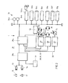
- Fig. 2 shows an electronic block diagram of the hydrostatic travel drive 1 corresponding to that shown in Fig. 1 Embodiment.
- control transmitter 33 comprises two Control levers 34a and 34b that have an electrical bus system on the one hand with the travel drive control 29 as well on the other hand directly with different hydraulic Components 50a to 50g of the vehicle to be driven connected, perform the work functions on the crane, such as Swiveling, lifting and actuating the boom, telescope, Crane foot and steering.
- These hydraulic components 50a to 50g are in turn open to the inlet line 11 Hydraulic circuit 9 preferably via load-sensing valves connected.
- the control via the bus system is in the Relative to a hydraulic control flexible and easy to set up.
- the drive control 29 consists of the actual one Control component 29a and the vehicle electrical system 29b.
- the Vehicle electronics 29b have inputs / outputs 53 and 54 which, for example, the sensors 35 and 37 are connected could be. However, at these inputs / outputs 53, 54 also, for example, lighting components of the vehicle or other operating components are connected.
- the Vehicle electronics 29b has a display 51, which the functions of the vehicle by the operator can be monitored. All components are over Bus systems connected to each other. About the Travel drive control 29 takes place as described Control of the drive of the front axles 17, 20 and Rear axle 36 via the hydraulic pump 4 and the hydraulic motor 12 of the closed hydraulic circuit 6 or that Control valve 21 of the open hydraulic circuit 9.
- Control receiver 57 is used to control the travel drive
- the control receiver 58 is used to control the steering
- the control receiver 59 is used to control the second Hydraulic pump 5.
- the electronic control components ensure a high Flexibility. Due to the modular structure, this can be done easily expand the system for new components.
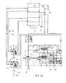
- Figures 3A and 3B show an embodiment of the Travel drive according to the invention in a compared to FIG. 1st detailed representation. To facilitate the assignment are already described components with matching Provide reference numerals.
- the closed hydraulic circuit 6 includes the Hydraulic pump 4 and the hydraulic motor 12, which via the lines 7th and 8 are connected. Is located on the drive shaft 3 an auxiliary pump 60, the hydraulic fluid over a Pressure relief valve 61 and a filter 62 and one of the two check valves 63 and 64 in the straight low pressure leading line 7 or 8 feeds. To limit the pressure of the straight high-pressure line 7 and 8 serve two Pressure relief valves 65 and 66.
- the adjustment device 67 of the hydraulic pump 4 is by means of a pilot valve 68 two electromagnets 69 and 70 electromagnetic adjusted.
- the Adjustment device 71 of the first hydraulic motor 12 via a Electromagnetically adjustable control valve 72 electrically driven.
- the mechanical gearbox 73 is a Differential gear 74 connected downstream.
- a part of Drive control 29 is shown in Embodiment designed hydraulically, two Control outputs 75 and 76 of the drive control 29 that Activate manual gearbox 73.
- a control output 77 of the Travel drive control 29 controls a braking device 78 the front vehicle axles 17 and 20, while two Control outputs 79 and 80 two braking devices 81 and 82 of the second hydraulic motor 22 and the third hydraulic motor 24 drive.
- the braking devices 78, 81 and 82 serve that rapid stopping of the travel drive when braking the Vehicle.
- the invention combines the advantages of a drive with closed hydraulic circuit 6 with the advantages of a Open hydraulic circuit drive 9.
- drive control 29 can also the function of leveling the drive wheels take.
- the hydraulic pumps 4 and 5 are preferably so dimensioned that they have a sufficient flow rate already available at low speed to to avoid unnecessary noise.
- the Functions of the hydrostatic drive and the Functions of the additional hydraulic components 38 or 50a to 50g can with predetermined priorities be provided so that when reaching the maximum Delivery volume of the hydraulic pump 5 only certain preferred Functions, such as the drive and the Curve control can be maintained.
- the invention relates to a hydrostatic Travel drive 1 with a first hydraulic pump 4 and one with the first hydraulic pump 4 in a closed Hydraulic circuit 6 via a flow line 7 and a Return line 8 connected first hydraulic motor 12, the drives at least a first vehicle wheel 14, 15, 18, 19.
- the inlet line 11 is the open Hydraulic circuit 9 a control valve 21 arranged, the the second hydraulic motor 22 a variable volume flow feeds the one of the control valve 21 driving Control signal is dependent.
- the first hydraulic motor 12 preferably drives the Vehicle wheels 14, 15 of at least one first vehicle axle 17 and on the control valve 21 next to the second one
- a third hydraulic motor 24 is connected to the hydraulic motor 22, the second hydraulic motor 22 and the third hydraulic motor 24 opposite vehicle wheels 23, 25 a second Drive the vehicle axle 36 and the control valve 21 so is designed to be dependent on the control signal the second hydraulic motor 22 and the third hydraulic motor 23 supplies separate, variable volume flows.
- the second and the third hydraulic motor 22 are preferably 24 via the control valve 21 with the hydraulic fluid tank 10 connected.
- control valve 21 Drive control 29 connected depending on a detected actual kink angle ⁇ between the first Vehicle axis 17 and the second vehicle axis 36 and / or a detected actual speed n at least one of the Vehicle axles 17, 36 controls the control valve 21 so that this the second and third hydraulic motor 22, 24 such separate volume flows that the vehicle wheels 23, 25 of the second vehicle axle 36 rotate without slip.
- the travel drive control 29 preferably controls Dependency on one by means of a control transmitter 33 Predeterminable set buckling angle ⁇ 'between the first Vehicle axis 17 and the second vehicle axis 36 and / or the control valve 21 at a predeterminable target speed n ', that this the second and third hydraulic motor 22, 24 such separate volume flows that the actual kink angle ⁇ to the target articulation angle ⁇ 'and / or the actual speed n approaches the target speed n '.
- the drive control 29 preferably controls this Control valve 21 and / or adjusting devices 67 of the Hydraulic pumps 4, 5 and / or an adjustment device 71 des first hydraulic motor 12 electrically.
- the open hydraulic circuit 9 further hydraulic components 38, 50a-50g, in particular the hydraulic components of a crane.
- the first hydraulic pump 4 and the second are preferred Hydraulic pump 5 from a common internal combustion engine 2 driven.
Landscapes
- Engineering & Computer Science (AREA)
- General Engineering & Computer Science (AREA)
- Mechanical Engineering (AREA)
- Motor Power Transmission Devices (AREA)
- Control Of Fluid Gearings (AREA)
- Operation Control Of Excavators (AREA)
Abstract
Description
- Fig. 1
- ein hydraulisches Prinzipschaltbild eines ersten Ausführungsbeispiels der Erfindung;
- Fig. 2
- ein elektronisches Prinzipschaltbild des ersten Ausführungsbeispiels der Erfindung;
- Fig. 3A
- einen ersten Teil eines hydraulischen Schaltbilds eines zweiten Ausführungsbeispiels der Erfindung; und
- Fig. 3B
- den zweiten Teil des hydraulischen Schaltbilds des zweiten Ausführungsbeispiels der Erfindung.
Claims (8)
- Hydrostatischer Fahrantrieb (1) mit einer ersten Hydropumpe (4) und einem mit der ersten Hydropumpe (4) in einem geschlossenen Hydraulikkreislauf (6) über eine Vorlaufleitung (7) und eine Rücklaufleitung (8) verbundenen ersten Hydromotor (12), der zumindest ein erstes Fahrzeugrad (14, 15, 18, 1.9) antreibt,
mit einer zweiten Hydropumpe (5) und einem mit der zweiten Hydropumpe (5) in einem offenen Hydraulikkreislauf (9) über eine Zulaufleitung (11) verbundenen zweiten Hydromotor (22), der zumindest ein zweites Fahrzeugrad (23) antreibt, wobei die Rückführung des Hydraulikfluids von dem zweiten Hydromotor (22) zu der zweiten Hydropumpe (5) über einen Hydraulikfluid-Tank (10) erfolgt,
wobei in der Zulaufleitung (11) des offenen Hydraulikkreislaufs (9) ein Steuerventil (21) angeordnet ist, das dem zweiten Hydromotor (22) einen variablen Volumenstrom zuführt, der von einem das Steuerventil (21) ansteuernden Steuersignal abhängig ist,
dadurch gekennzeichnet, daß oberhalb einer Grenzgeschwindigkeit eines mittels des hydrostatischen Fahrantriebs (1) angetriebenen Fahrzeugs das Steuerventil (21) die daran angeschlossenen Hydromotoren (22, 24) in einen Freilaufbetrieb umschaltet und der Antrieb dann ausschließlich über den geschlossenen Hydraulikkreislauf (6) erfolgt. - Hydrostatischer Fahrantrieb nach Anspruch 1,
dadurch gekennzeichnet, daß der erste Hydromotor (12) die Fahrzeugräder (14, 15) zumindest einer ersten Fahrzeugachse (17) antreibt, und daß an dem Steuerventil (21) neben dem zweiten Hydromotor (22) ein dritter Hydromotor (24) angeschlossen ist, wobei der zweite Hydromotor (22) und der dritte Hydromotor (24) gegenüberliegende Fahrzeugräder (23, 25) einer zweiten Fahrzeugachse (36) antreiben und das Steuerventil (21) so ausgebildet ist, daß es in Abhängigkeit von dem Steuersignal dem zweiten Hydromotor (22) und dem dritten Hydromotor (23) separate, variable Volumenströme zuführt. - Hydrostatischer Fahrantrieb nach Anspruch 2,
dadurch gekennzeichnet, daß der zweite und der dritte Hydromotor (22, 24) über das Steuerventil (21) mit dem Hydraulikfluid-Tank (10) verbunden sind. - Hydrostatischer Fahrantrieb nach Anspruch 2 oder 3,
dadurch gekennzeichnet, daß mit dem Steuerventil (21) eine Fahrantriebssteuerung (29) verbunden ist, die in Abhängigkeit von einem erfaßten Istknickwinkel (α) zwischen der ersten Fahrzeugachse (17) und der zweiten Fahrzeugachse (36) und/oder einer erfaßten Istdrehzahl (n) zumindest einer der Fahrzeugachsen (17, 36) das Steuerventil (21) so ansteuert, daß dieses dem zweiten und dritten Hydromotor (22, 24) solche separate Volumenströme zuführt, daß sich die Fahrzeugräder (23, 25) der zweiten Fahrzeugachse (36) schlupffrei drehen. - Hydrostatischer Fahrantrieb nach Anspruch 4,
dadurch gekennzeichnet, daß die Fahrantriebssteuerung (29) in Abhängigkeit von einem mittels eines Steuergebers (33) vorgebbaren Sollknickwinkel (α') zwischen der ersten Fahrzeugachse (17) und der zweiten Fahrzeugachse (36) und/oder einer vorgebbaren Solldrehzahl (n') das Steuerventil (21) so ansteuert, daß dieses dem zweiten und dritten Hydromotor (22, 24) solche separate Volumenströme zuführt, daß sich der Istknickwinkel (α) an den Sollknickwinkel (α') und/oder die Istdrehzahl (n) an die Solldrehzahl (n') annähert. - Hydrostatischer Fahrantrieb nach Anspruch 4 oder 5,
dadurch gekennzeichnet, daß die Fahrantriebssteuerung (29) das Steuerventil (21) und/oder Verstellvorrichtungen (67) der Hydropumpen (4, 5) und/oder eine Verstellvorichtung (71) des ersten Hydromotors (12) elektrisch ansteuert. - Hydrostatischer Fahrantrieb nach einem der vorherigen Ansprüche,
dadurch gekennzeichnet, daß von dem offenen Hydraulikkreislauf (9) weitere hydraulische Komponenten (38, 50a-50g), insbesondere die hydraulischen Komponenten eines Krans, angetrieben werden. - Hydrostatischer Fahrantrieb nach einem der vorherigen Ansprüche,
dadurch gekennzeichnet, daß die erste Hydropumpe (4) und die zweite Hydropumpe (5) von einem gemeinsamen Verbrennungsmotor (2) angetrieben werden.
Applications Claiming Priority (3)
| Application Number | Priority Date | Filing Date | Title |
|---|---|---|---|
| DE19923516 | 1999-05-21 | ||
| DE19923516A DE19923516A1 (de) | 1999-05-21 | 1999-05-21 | Hydrostatischer Fahrantrieb |
| EP00931191A EP1178895B1 (de) | 1999-05-21 | 2000-05-10 | Hydrostatischer fahrantrieb |
Related Parent Applications (1)
| Application Number | Title | Priority Date | Filing Date |
|---|---|---|---|
| EP00931191A Division EP1178895B1 (de) | 1999-05-21 | 2000-05-10 | Hydrostatischer fahrantrieb |
Publications (3)
| Publication Number | Publication Date |
|---|---|
| EP1325833A2 true EP1325833A2 (de) | 2003-07-09 |
| EP1325833A3 EP1325833A3 (de) | 2007-03-14 |
| EP1325833B1 EP1325833B1 (de) | 2008-03-05 |
Family
ID=7908855
Family Applications (2)
| Application Number | Title | Priority Date | Filing Date |
|---|---|---|---|
| EP03006245A Expired - Lifetime EP1325833B1 (de) | 1999-05-21 | 2000-05-10 | Hydrostatischer Fahrantrieb |
| EP00931191A Expired - Lifetime EP1178895B1 (de) | 1999-05-21 | 2000-05-10 | Hydrostatischer fahrantrieb |
Family Applications After (1)
| Application Number | Title | Priority Date | Filing Date |
|---|---|---|---|
| EP00931191A Expired - Lifetime EP1178895B1 (de) | 1999-05-21 | 2000-05-10 | Hydrostatischer fahrantrieb |
Country Status (5)
| Country | Link |
|---|---|
| US (1) | US6702055B1 (de) |
| EP (2) | EP1325833B1 (de) |
| CA (1) | CA2371444C (de) |
| DE (3) | DE19923516A1 (de) |
| WO (1) | WO2000071379A1 (de) |
Cited By (1)
| Publication number | Priority date | Publication date | Assignee | Title |
|---|---|---|---|---|
| CN103522896A (zh) * | 2013-07-30 | 2014-01-22 | 山东临工工程机械有限公司 | 平地机前轮辅助驱动系统 |
Families Citing this family (2)
| Publication number | Priority date | Publication date | Assignee | Title |
|---|---|---|---|---|
| DE102004021839A1 (de) * | 2004-05-04 | 2005-12-01 | Liebherr-Werk Nenzing Gmbh, Nenzing | Telelader, insbesondere Reachstacker |
| US10808839B2 (en) | 2018-01-24 | 2020-10-20 | Cnh Industrial America Llc | Method and system for controlling a hydrostatic drive system of an agricultural vehicle |
Family Cites Families (8)
| Publication number | Priority date | Publication date | Assignee | Title |
|---|---|---|---|---|
| GB1341361A (en) * | 1972-01-13 | 1973-12-19 | Cmi Corp | Hydrostatic drive system |
| US3978937A (en) * | 1974-09-23 | 1976-09-07 | Clark Equipment Company | Hydrostatic propulsion system |
| US4635743A (en) * | 1984-04-12 | 1987-01-13 | Dresser Industries, Inc. | Vehicle front wheel assist drive overspeed control system |
| JPH08177010A (ja) * | 1994-12-21 | 1996-07-09 | Komatsu Esuto:Kk | 回転式切削機を備えた車両の走行装置 |
| DE19524189C2 (de) | 1995-07-03 | 1997-07-17 | Brueninghaus Hydromatik Gmbh | Hydrostatischer Antrieb mit nachgeschaltetem Lastschaltgetriebe |
| FR2741130B1 (fr) * | 1996-03-29 | 1998-02-13 | Poclain Hydraulics Sa | Transmission hydrostatique d'un engin mobile |
| JPH1044803A (ja) * | 1996-07-31 | 1998-02-17 | Komatsu Ltd | 油圧式四駆車両 |
| DE19750367C2 (de) * | 1997-11-14 | 2001-07-05 | Danfoss Fluid Power As Nordbor | Hydraulischer Fahrzeugantrieb und Ventilmodul hierfür |
-
1999
- 1999-05-21 DE DE19923516A patent/DE19923516A1/de not_active Withdrawn
-
2000
- 2000-05-10 WO PCT/EP2000/004263 patent/WO2000071379A1/de not_active Ceased
- 2000-05-10 DE DE50007135T patent/DE50007135D1/de not_active Expired - Lifetime
- 2000-05-10 EP EP03006245A patent/EP1325833B1/de not_active Expired - Lifetime
- 2000-05-10 EP EP00931191A patent/EP1178895B1/de not_active Expired - Lifetime
- 2000-05-10 US US09/979,342 patent/US6702055B1/en not_active Expired - Fee Related
- 2000-05-10 DE DE50015031T patent/DE50015031D1/de not_active Expired - Fee Related
- 2000-05-10 CA CA002371444A patent/CA2371444C/en not_active Expired - Fee Related
Cited By (2)
| Publication number | Priority date | Publication date | Assignee | Title |
|---|---|---|---|---|
| CN103522896A (zh) * | 2013-07-30 | 2014-01-22 | 山东临工工程机械有限公司 | 平地机前轮辅助驱动系统 |
| CN103522896B (zh) * | 2013-07-30 | 2016-03-30 | 山东临工工程机械有限公司 | 平地机前轮辅助驱动系统 |
Also Published As
| Publication number | Publication date |
|---|---|
| DE50007135D1 (de) | 2004-08-26 |
| EP1325833A3 (de) | 2007-03-14 |
| WO2000071379A1 (de) | 2000-11-30 |
| US6702055B1 (en) | 2004-03-09 |
| EP1178895B1 (de) | 2004-07-21 |
| CA2371444A1 (en) | 2000-11-30 |
| EP1178895A1 (de) | 2002-02-13 |
| DE19923516A1 (de) | 2000-11-23 |
| EP1325833B1 (de) | 2008-03-05 |
| DE50015031D1 (de) | 2008-04-17 |
| CA2371444C (en) | 2008-03-11 |
Similar Documents
| Publication | Publication Date | Title |
|---|---|---|
| EP0743219B1 (de) | Strassenfertiger | |
| DE102012111857A1 (de) | Ein von Hybrid-Motor angetriebenes Lenkhilfesystem für ein Nutzfahrzeug und Verfahren zum Verbessern von Leistungsfähigkeit und Kraftstoffeffizienz mittels Steuerung desselben | |
| EP0947414B1 (de) | Lenksteuersystem für Raupenfahrzeug | |
| DE4219876C2 (de) | Radfahrzeug, insbesondere Forstmaschine | |
| EP1188642B1 (de) | Steuerung eines Fahr-/Lenksystems für ein Raupenfahrzeug | |
| DE3308295A1 (de) | Fahrzeug | |
| DE2052084A1 (de) | Fahrzeugachse in Gehäuseform | |
| EP3437961A1 (de) | Hydraulisches lenksystem | |
| EP1031494B1 (de) | Steuersystem für Raupenfahrzeuge | |
| EP3569775B1 (de) | Hydraulische anordnung mit retarderfunktion und fahrantrieb damit | |
| EP1178895B1 (de) | Hydrostatischer fahrantrieb | |
| DE10138563B4 (de) | Rad-Straßenfertiger und Verfahren zum Lenken eines Rad-Straßenfertigers | |
| DE3620163A1 (de) | Verfahren zur steuerung oder reglung eines hydrostatischen antriebs ueber die vorderraeder eines fahrzeugs mit mechanischem, hydrodynamischem oder hydrostatischem getriebe und verbrennungskolbenmotor als heckantrieb und anordnung zur durchfuehrung des verfahrens | |
| EP1561054B1 (de) | Steuerung für einen hydrostatischen fahrantrieb | |
| EP1718490B1 (de) | Verfahren zum betrieb einer mit einem antriebsmotor gekoppelten wegzapfwelle | |
| DE3941024C2 (de) | ||
| DE4301745C1 (de) | Verfahren zur Steuerung des Lenkverhaltens einer mobilen Baumaschine sowie Lenkung für die Baumaschine | |
| DE19939474C2 (de) | Hydrostatischer Fahrantrieb mit Antischlupfregelung | |
| AT621U1 (de) | Antriebssteuerung eines einachstraktors | |
| EP1144238B1 (de) | Verfahren zum lenken und antreiben einer selbstfahrenden arbeitsmaschine und selbstfahrende arbeitsmaschine | |
| DE10135862A1 (de) | Fahrzeuglenkung | |
| EP1508498A2 (de) | Lenksystem für ein Kraftfahrzeug mit einer Servolenkeinrichtung | |
| DE102006036317A1 (de) | Verfahren zur Steuerung eines Übersetzungsverhältnisses | |
| EP3513996B1 (de) | Fahrzeug, insbesondere landwirtschaftliches fahrzeug | |
| DE8218816U1 (de) | Fahrzeug fuer anbaubares schweres arbeitsgeraet |
Legal Events
| Date | Code | Title | Description |
|---|---|---|---|
| PUAI | Public reference made under article 153(3) epc to a published international application that has entered the european phase |
Free format text: ORIGINAL CODE: 0009012 |
|
| 17P | Request for examination filed |
Effective date: 20030320 |
|
| AC | Divisional application: reference to earlier application |
Ref document number: 1178895 Country of ref document: EP Kind code of ref document: P |
|
| AK | Designated contracting states |
Designated state(s): DE FI FR GB IT SE |
|
| RIN1 | Information on inventor provided before grant (corrected) |
Inventor name: RINCK, STEFAN Inventor name: PEKKANEN, JUKKA Inventor name: BRAND, MICHAEL |
|
| PUAL | Search report despatched |
Free format text: ORIGINAL CODE: 0009013 |
|
| RIC1 | Information provided on ipc code assigned before grant |
Ipc: B60K 17/356 20060101AFI20030429BHEP Ipc: F16H 39/02 20060101ALI20070201BHEP |
|
| AK | Designated contracting states |
Kind code of ref document: A3 Designated state(s): DE FI FR GB IT SE |
|
| GRAP | Despatch of communication of intention to grant a patent |
Free format text: ORIGINAL CODE: EPIDOSNIGR1 |
|
| AKX | Designation fees paid |
Designated state(s): DE FI FR GB IT SE |
|
| GRAS | Grant fee paid |
Free format text: ORIGINAL CODE: EPIDOSNIGR3 |
|
| GRAA | (expected) grant |
Free format text: ORIGINAL CODE: 0009210 |
|
| AC | Divisional application: reference to earlier application |
Ref document number: 1178895 Country of ref document: EP Kind code of ref document: P |
|
| AK | Designated contracting states |
Kind code of ref document: B1 Designated state(s): DE FI FR GB IT SE |
|
| REG | Reference to a national code |
Ref country code: GB Ref legal event code: FG4D Free format text: NOT ENGLISH |
|
| GBT | Gb: translation of ep patent filed (gb section 77(6)(a)/1977) |
Effective date: 20080305 |
|
| REF | Corresponds to: |
Ref document number: 50015031 Country of ref document: DE Date of ref document: 20080417 Kind code of ref document: P |
|
| ET | Fr: translation filed | ||
| PLBE | No opposition filed within time limit |
Free format text: ORIGINAL CODE: 0009261 |
|
| STAA | Information on the status of an ep patent application or granted ep patent |
Free format text: STATUS: NO OPPOSITION FILED WITHIN TIME LIMIT |
|
| 26N | No opposition filed |
Effective date: 20081208 |
|
| PG25 | Lapsed in a contracting state [announced via postgrant information from national office to epo] |
Ref country code: DE Free format text: LAPSE BECAUSE OF NON-PAYMENT OF DUE FEES Effective date: 20081202 |
|
| PGFP | Annual fee paid to national office [announced via postgrant information from national office to epo] |
Ref country code: FR Payment date: 20120608 Year of fee payment: 13 Ref country code: FI Payment date: 20120521 Year of fee payment: 13 Ref country code: SE Payment date: 20120522 Year of fee payment: 13 Ref country code: GB Payment date: 20120522 Year of fee payment: 13 |
|
| PGFP | Annual fee paid to national office [announced via postgrant information from national office to epo] |
Ref country code: IT Payment date: 20130525 Year of fee payment: 14 |
|
| REG | Reference to a national code |
Ref country code: SE Ref legal event code: EUG |
|
| GBPC | Gb: european patent ceased through non-payment of renewal fee |
Effective date: 20130510 |
|
| PG25 | Lapsed in a contracting state [announced via postgrant information from national office to epo] |
Ref country code: SE Free format text: LAPSE BECAUSE OF NON-PAYMENT OF DUE FEES Effective date: 20130511 |
|
| PG25 | Lapsed in a contracting state [announced via postgrant information from national office to epo] |
Ref country code: FI Free format text: LAPSE BECAUSE OF NON-PAYMENT OF DUE FEES Effective date: 20130510 |
|
| REG | Reference to a national code |
Ref country code: FR Ref legal event code: ST Effective date: 20140131 |
|
| PG25 | Lapsed in a contracting state [announced via postgrant information from national office to epo] |
Ref country code: GB Free format text: LAPSE BECAUSE OF NON-PAYMENT OF DUE FEES Effective date: 20130510 |
|
| PG25 | Lapsed in a contracting state [announced via postgrant information from national office to epo] |
Ref country code: FR Free format text: LAPSE BECAUSE OF NON-PAYMENT OF DUE FEES Effective date: 20130531 |
|
| PG25 | Lapsed in a contracting state [announced via postgrant information from national office to epo] |
Ref country code: IT Free format text: LAPSE BECAUSE OF NON-PAYMENT OF DUE FEES Effective date: 20140510 |