EP1321730A2 - Niederdrucksammler, insbesondere für eine CO2-Klimaanlage - Google Patents
Niederdrucksammler, insbesondere für eine CO2-Klimaanlage Download PDFInfo
- Publication number
- EP1321730A2 EP1321730A2 EP02027540A EP02027540A EP1321730A2 EP 1321730 A2 EP1321730 A2 EP 1321730A2 EP 02027540 A EP02027540 A EP 02027540A EP 02027540 A EP02027540 A EP 02027540A EP 1321730 A2 EP1321730 A2 EP 1321730A2
- Authority
- EP
- European Patent Office
- Prior art keywords
- oil
- low
- refrigerant
- phase
- pressure accumulator
- Prior art date
- Legal status (The legal status is an assumption and is not a legal conclusion. Google has not performed a legal analysis and makes no representation as to the accuracy of the status listed.)
- Granted
Links
Images

Classifications
-
- F—MECHANICAL ENGINEERING; LIGHTING; HEATING; WEAPONS; BLASTING
- F25—REFRIGERATION OR COOLING; COMBINED HEATING AND REFRIGERATION SYSTEMS; HEAT PUMP SYSTEMS; MANUFACTURE OR STORAGE OF ICE; LIQUEFACTION SOLIDIFICATION OF GASES
- F25B—REFRIGERATION MACHINES, PLANTS OR SYSTEMS; COMBINED HEATING AND REFRIGERATION SYSTEMS; HEAT PUMP SYSTEMS
- F25B43/00—Arrangements for separating or purifying gases or liquids; Arrangements for vaporising the residuum of liquid refrigerant, e.g. by heat
- F25B43/006—Accumulators
-
- F—MECHANICAL ENGINEERING; LIGHTING; HEATING; WEAPONS; BLASTING
- F25—REFRIGERATION OR COOLING; COMBINED HEATING AND REFRIGERATION SYSTEMS; HEAT PUMP SYSTEMS; MANUFACTURE OR STORAGE OF ICE; LIQUEFACTION SOLIDIFICATION OF GASES
- F25B—REFRIGERATION MACHINES, PLANTS OR SYSTEMS; COMBINED HEATING AND REFRIGERATION SYSTEMS; HEAT PUMP SYSTEMS
- F25B2309/00—Gas cycle refrigeration machines
- F25B2309/06—Compression machines, plants or systems characterised by the refrigerant being carbon dioxide
-
- F—MECHANICAL ENGINEERING; LIGHTING; HEATING; WEAPONS; BLASTING
- F25—REFRIGERATION OR COOLING; COMBINED HEATING AND REFRIGERATION SYSTEMS; HEAT PUMP SYSTEMS; MANUFACTURE OR STORAGE OF ICE; LIQUEFACTION SOLIDIFICATION OF GASES
- F25B—REFRIGERATION MACHINES, PLANTS OR SYSTEMS; COMBINED HEATING AND REFRIGERATION SYSTEMS; HEAT PUMP SYSTEMS
- F25B43/00—Arrangements for separating or purifying gases or liquids; Arrangements for vaporising the residuum of liquid refrigerant, e.g. by heat
- F25B43/02—Arrangements for separating or purifying gases or liquids; Arrangements for vaporising the residuum of liquid refrigerant, e.g. by heat for separating lubricants from the refrigerant
-
- F—MECHANICAL ENGINEERING; LIGHTING; HEATING; WEAPONS; BLASTING
- F25—REFRIGERATION OR COOLING; COMBINED HEATING AND REFRIGERATION SYSTEMS; HEAT PUMP SYSTEMS; MANUFACTURE OR STORAGE OF ICE; LIQUEFACTION SOLIDIFICATION OF GASES
- F25B—REFRIGERATION MACHINES, PLANTS OR SYSTEMS; COMBINED HEATING AND REFRIGERATION SYSTEMS; HEAT PUMP SYSTEMS
- F25B9/00—Compression machines, plants or systems, in which the refrigerant is air or other gas of low boiling point
- F25B9/002—Compression machines, plants or systems, in which the refrigerant is air or other gas of low boiling point characterised by the refrigerant
- F25B9/008—Compression machines, plants or systems, in which the refrigerant is air or other gas of low boiling point characterised by the refrigerant the refrigerant being carbon dioxide
Definitions
- the invention relates to a low-pressure collector, in particular for a CO2 air conditioning system for a motor vehicle, according to the preamble of the claim 1, an air conditioner according to the preamble of claim 13 and a method of operating a low pressure accumulator according to the Preamble of claim 14.
- CO2 air conditioning systems usually have a low-pressure accumulator of initially mentioned type, which at different operating points fluctuating need for refrigerant in the circuit of the air conditioning buffers.
- the low-pressure collector is gaseous refrigerant, liquid refrigerant and one with the liquid refrigerant only limited miscible oil, which usually contain some liquid in the liquid refrigerant is and some oil in the oil, so that the corresponding phases in the The following are referred to as oil-poor or oil-rich phases.
- the oil rich Phase settles due to its greater density in the low pressure collector down from and is fed back to the extracted, gaseous refrigerant.
- a corresponding low-pressure accumulator according to the prior art is shown in Fig. 4.
- This low pressure accumulator 210 has a housing 211, a supply line 212 and a drain 213 on.
- the gaseous refrigerants 214 in the middle part the low-oil phase 215 and in the lower part of the oil-rich phase 216, as shown schematically in Fig. 4.
- the supply line 212 terminates in the upper region of the low-pressure accumulator 210 and carries gaseous refrigerant 214, as well as a small amount of liquid, consisting of oil and refrigerant, the low pressure accumulator 210 to.
- the disadvantage of such an arrangement is that it falls below a threshold temperature comes to a floating of the oil-rich phase, so that the oil return mechanism which passed the oil-rich phase to the gaseous refrigerant supplies failed.
- the limit temperature currently oil and CO2 at approx. -20 ° C. These temperatures can occur when the system is used as a heat pump at low ambient temperatures is used.
- failure of the oil return mechanism There is an accumulation of oil in the low pressure collector and thus to a depletion of the circulating oil in the Circulation. As a result, there may be compressor damage due to deficient Lubrication due to insufficient oil supply come.
- an intermediate container is provided for this purpose.
- a simple separation of liquid refrigerant and oil is by means of a liquid-permeable wall possible.
- the wall in particular be designed porous or holes of small diameter respectively.
- the separation of the oil-rich and oil-poor phase is based on the different viscosity of both phases.
- the permeability must be designed so that on the one hand the low-oil phase is fast, that only a small proportion remains in the intermediate container, on the other hand so accumulated a lot of oil-rich phase in the intermediate tank, that this the derivative can be supplied.
- the Low pressure collector preferably a mixing device, which the Separating device is connected upstream and which the mixing of the oil-poor and the oil-rich phases, so that a refrigerant-oil mixture of the Separating device is supplied.
- This is preferably the supplied, mostly gaseous refrigerant for mixing around the lower Part of the housing located low oil and oil-rich phases, where it can also act as a means of transport to the refrigerant-oil mixture to feed the separator.
- the supply line for the refrigerant is preferably in the lower region of the low-pressure accumulator.
- an oil return line provided for the derivation, wherein the oil return line has a smaller Diameter as the derivative and of a height the intermediate container emanates middle region of the intermediate container, whereby a floating of the oil or the oil-rich phase in the intermediate container is unproblematic, as it also in this case to the oil return line and thus to the derivative and get back into the circulation.
- Middle range means here that the oil return line is not directly at Bottom or directly at the top of the intermediate container begins.
- the separating device is a Calming device, preferably in the form of a cascade upstream.
- Fig. 1 shows a CO2 air conditioner 1 with a compressor 2, a heat exchanger 3, which heat between refrigerant and ambient air transfers, an internal heat exchanger 4, which heat between two Streaming of the refrigerant transfers, an expansion element 5, a heat exchanger 6, which heat between the refrigerant and the Vehicle interior supplied air transfers, as well as a 4/2-way valve 7, which switches the refrigerant flow so that the system alternatively for cooling or heating the vehicle interior supplied Air is used, and a low-pressure accumulator 10 according to the first embodiment, which is shown schematically in Fig. 2.
- the refrigerant leaving the compressor 2 is from the 4/2-way valve 7 passed to the heat exchanger 3 and there gives heat to the Ambient air.
- the cooled refrigerant is then inside Heat exchanger 4 further cooled. It will be in the expansion organ 5 then throttled to a low pressure and evaporated in the heat exchanger 6, wherein it is the heat supplied to the vehicle interior air withdraws. Then it is via the 4/2-way valve 7 via a Line 12 fed to the low pressure accumulator 10, flows through the inner Heat exchanger 4, where it heats up and finally from the compressor 2 is brought back to high pressure.
- the refrigerant is starting from the compressor 2 via the 4/2-way valve 7 is passed to the heat exchanger 6, where it cools down and in return, the air supplied to the vehicle interior heats up. It will subsequently expanded by the expansion element 5 to a low pressure, flows through the internal heat exchanger 4 without essential function and evaporates in the heat exchanger 3, where it is the ambient air heat withdraws. Then it is from the 4/2-way valve 7 to the low pressure collector 10 and via the inner heat exchanger 4 to the compressor. 2 where it is put back on high pressure. In heating mode can it correspondingly at correspondingly low ambient temperatures come low evaporation temperatures, which for the floating of the Oils lead.
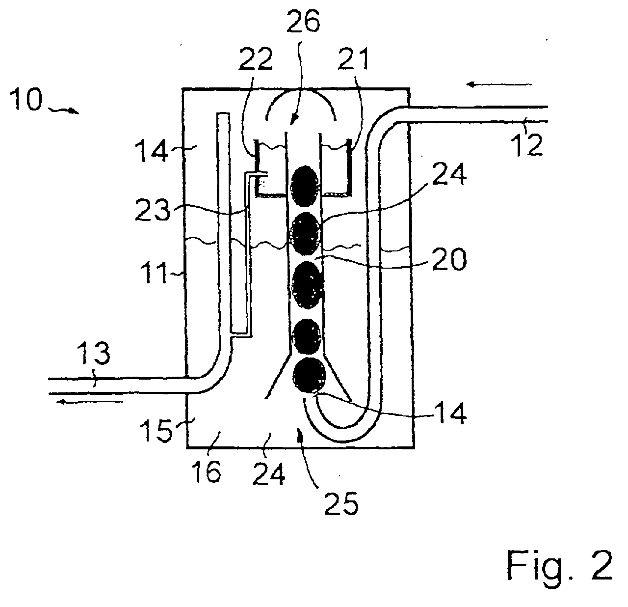
- the low pressure accumulator 10 has, as shown in Fig. 2, a housing 11th which is supplied by means of a supply line 12 refrigerant and by means of a Derivation 13 is removed again.
- the housing 11 contains gaseous Refrigerant 14 in the upper part of the housing 11, as well as liquid refrigerant 15 and oil 16 in the lower part of the housing 11th
- the refrigerant supplied through the supply line 12 is predominantly gaseous, as well as the derivative through the derivative 13 refrigerant.
- the supply line 12 terminates in the lower part of the housing 11, in an area in the the liquid refrigerant 15 and the oil 16 are located. It ends below a vertically arranged, funnel - shaped open line 20, which in Upper part of the housing 11 ends, in an area in which the gaseous Refrigerant 14 is located. At this upper end is on the line 20 an upwardly open intermediate container 21 with walls 22 such provided that the line 20 the intermediate container 21 from below penetrates and slightly above the walls 22 of the intermediate container 21 ends. In this case, the intermediate container 21 above the lower in the Part of the housing 11 located liquid refrigerant 15 and the oil 16 arranged.
- the walls 22 of the intermediate container 21 are porous, wherein the Function will be described in more detail later.
- the diameter of the oil return line 23 is smaller as the diameter of the derivative 13.
- the feed line 12 serves as a mixing device 25th
- the supplied gaseous refrigerant 14 breaks a part of the refrigerant-oil mixture 24 with and transports them through the line 20 in the intermediate container 21.
- the porous walls 22nd there is an accumulation of the more viscous phase, i.
- the intermediate container 21 thus serves as a separator 26 for liquid refrigerant 15 and oil 16, wherein the oil 16 accumulates in the intermediate container 21.
- porous walls 22 As an alternative to porous walls 22 corresponding small openings be provided in the walls 22, which leads to a separation of Refrigerant-oil mixture 24 lead.
- oil 16 passes through the oil return line 23 for discharge 13, while the liquid refrigerant 15 remains in the low-pressure accumulator 10. Since the oil return line 23 is approximately in the middle of the height of the porous walls 22 branches off laterally from the intermediate container 21, it is ensured that even in case of floating of oil 16 at very low Temperatures especially oil 16 through the oil return line 23 of the derivative 13 is supplied and no or only in minimal quantities liquid refrigerant 15 instead of oil 16 enters the circuit.
- Fig. 3 shows the second embodiment.
- the same or equivalent elements with reference numerals higher by 100 than in the first Designated embodiment.
- the low-pressure collector 110 also has a housing 111 with a in the lower part of the housing 111 ending supply line 112 and one in the upper Part of the housing 111 beginning discharge 113.
- gaseous refrigerant 114 in the upper part, as well as liquid refrigerant 115 and oil 116 in the lower part of the housing 111 included.
- the first embodiment is performed by the through the supply line 112 supplied gaseous refrigerant 114 mixing the im lower part of the housing 111 befindliches liquid Kältemitteis 115 and of the oil 116, so that in turn a refrigerant-oil mixture 124 is formed.
- the feed line 112 according to the first embodiment as mixing device 125.
- the first embodiment is in the housing 111 in the provided substantially vertically disposed line 120, which below funnel-shaped and ends open at the top.
- the upper end of the conduit 120 is a calming device 120 'in shape a cascade 120 ", which is used to reduce turbulence in the refrigerant-oil mixture 124, which is below the cascade 120 "arranged intermediate container 121 is thus supplied calmed
- Intermediate container 121 has, according to the first embodiment, porous walls 122, through which the liquid refrigerant 115 exit and get back into the lower part of the low pressure header 110 where most of the refrigerant-oil mixture 124 is located during the oil 116 in serving as a separator 126 intermediate container 121 enriches.
- an oil return line 125 from the discharge 113th
- the function of the low-pressure accumulator 110 essentially corresponds to that the low pressure accumulator 10 according to the first embodiment.
Landscapes
- Engineering & Computer Science (AREA)
- Chemical & Material Sciences (AREA)
- Analytical Chemistry (AREA)
- Power Engineering (AREA)
- Physics & Mathematics (AREA)
- Mechanical Engineering (AREA)
- Thermal Sciences (AREA)
- General Engineering & Computer Science (AREA)
- Air-Conditioning For Vehicles (AREA)
- Motor Or Generator Cooling System (AREA)
- Pipe Accessories (AREA)
Abstract
Description
- Fig. 1
- eine schematische Darstellung einer CO2-Klimaanlag mit einem Niederdrucksammler gemäß dem ersten Ausführungsbeispiel,
- Fig. 2
- den Niederdrucksammler von Fig. 1,
- Fig. 3
- einen Niederdrucksammler gemäß dem zweiten Ausführungsbeispiel, und
- Fig. 4
- einen Niederdrucksammler gemäß dem Stand der Technik.
Claims (15)
- Niederdrucksammler, insbesondere für eine CO2-Klimaanlage (1) für ein Kraftfahrzeug, in welchem gasförmiges Kältemittel (14; 114), flüssiges Kältemittel in Form einer ölarmen Phase (15; 115) und Öl in Form einer ölreichen Phase (16; 116) enthalten ist, mit einer Zuleitung (12; 112) und einer Ableitung (13; 113) für das mit der ölreichen Phase (16; 116) versetzte Kältemittel (14; 114), dadurch gekennzeichnet, dass der Niederdrucksammler (10; 110) eine Trennvorrichtung (26; 126) aufweist.
- Niederdrucksammler nach Anspruch 1, dadurch gekennzeichnet, dass die Trennvorrichtung (26; 126) einen Zwischenbehälter (21; 121) aufweist.
- Niederdrucksammler nach einem der vorstehenden Ansprüche, dadurch gekennzeichnet, dass die Trennvorrichtung (26; 126) eine flüssigkeitsdurchlässige Wandung (22; 122) aufweist.
- Niederdrucksammler nach einem der vorstehenden Ansprüche, dadurch gekennzeichnet, dass die Trennvorrichtung (26; 126) im oberen Bereich des Niederdrucksammlers (10; 110) angeordnet ist.
- Niederdrucksammler nach einem der vorstehenden Ansprüche, dadurch gekennzeichnet, dass der Niederdrucksammler (10; 110) eine der Trennvorrichtung (26; 126) vorgeschaltete Mischvorrichtung (25; 125) aufweist.
- Niederdrucksammler nach Anspruch 5, dadurch gekennzeichnet, dass die Zufuhr des Kältemittels als Mischvorrichtung (25; 125) wirkt und die ölarme Phase (15; 115) und die ölreiche Phase (16; 116) vermischt.
- Niederdrucksammler nach einem der vorstehenden Ansprüche, dadurch gekennzeichnet, dass das zugeführte Kältemittel als Transportmittel wirkt und die ölarme Phase (15; 115) und die ölreiche Phase (16; 116) zur Trennvorrichtung (26; 126) transportiert.
- Niederdrucksammler nach einem der vorstehenden Ansprüche, dadurch gekennzeichnet, dass die Zuleitung (12; 112) im unteren Bereich des Niederdrucksammlers (10; 110) endet.
- Niederdrucksammler nach einem der Ansprüche 2 bis 8, dadurch gekennzeichnet, dass ausgehend vom Zwischenbehälter (21; 121) eine Ölrückführleitung (23; 123) zur Ableitung (13; 113) vorgesehen ist, wobei die Ölrückführleitung (23; 123) einen kleineren Durchmesser als die Ableitung (13; 113) aufweist und von einem bezüglich der Höhe des Zwischenbehälters (21; 121) mittleren Bereich des Zwischenbehälters (21; 121) ausgeht.
- Niederdrucksammler nach Anspruch 9, dadurch gekennzeichnet, dass die Eintrittsöffnung zur Ölrückführleitung (23; 123) unterhalb der Eintrittsöffnung zur Ableitung (13; 113) angeordnet ist.
- Niederdrucksammler nach einem der vorhergehenden Ansprüche, dadurch gekennzeichnet, dass vor der oder in der Trennvorrichtung (126) eine Beruhigungsvorrichtung (120') vorgesehen ist.
- Niederdrucksammler nach Anspruch 11, dadurch gekennzeichnet, dass als Beruhigungsvorrichtung (120') eine Kaskade (120") oberhalb vom Zwischenbehälter (121) angeordnet ist.
- Klimaanlage, insbesondere CO2-Klimaanlage, gekennzeichnet durch einen Niederdrucksammler (10; 110) gemäß einem der vorstehenden Ansprüche.
- Verfahren zum Betreiben eines Niederdrucksammlers (10; 110), insbesondere für eine CO2-Klimaanlage (1) für ein Kraftfahrzeug, in welchem gasförmiges Kältemittel (14; 114), flüssiges Kältemittel in Form einer ölarmen Phase (15; 115) und Öl in Form einer ölreichen Phase (16; 116) enthalten ist, mit einer Zuleitung (12; 112) und einer Ableitung (13; 113) für das mit der ölreichen Phase (16; 116) versetzte Kältemittel (14; 114), dadurch gekennzeichnet, dass im Niederdrucksammler (10; 110) die ölarme Phase (15; 115) und die ölreiche Phase (16; 116) mittels einer Trennvorrichtung (26; 126) getrennt werden.
- Verfahren nach Anspruch 14, dadurch gekennzeichnet, dass die ölarme Phase (15; 115) und die ölreiche Phase (16; 116) vor der Trennung mittels einer Mischvorrichtung (25; 125) vermischt werden.
Applications Claiming Priority (2)
| Application Number | Priority Date | Filing Date | Title |
|---|---|---|---|
| DE10161238A DE10161238A1 (de) | 2001-12-13 | 2001-12-13 | Niederdrucksammler, insbesondere für eine CO2-Klimaanlage |
| DE10161238 | 2001-12-13 |
Publications (3)
| Publication Number | Publication Date |
|---|---|
| EP1321730A2 true EP1321730A2 (de) | 2003-06-25 |
| EP1321730A3 EP1321730A3 (de) | 2003-10-08 |
| EP1321730B1 EP1321730B1 (de) | 2007-11-14 |
Family
ID=7709070
Family Applications (1)
| Application Number | Title | Priority Date | Filing Date |
|---|---|---|---|
| EP02027540A Expired - Lifetime EP1321730B1 (de) | 2001-12-13 | 2002-12-09 | Niederdrucksammler, insbesondere für eine CO2-Klimaanlage |
Country Status (3)
| Country | Link |
|---|---|
| EP (1) | EP1321730B1 (de) |
| AT (1) | ATE378563T1 (de) |
| DE (2) | DE10161238A1 (de) |
Cited By (5)
| Publication number | Priority date | Publication date | Assignee | Title |
|---|---|---|---|---|
| US7082785B2 (en) | 2004-07-13 | 2006-08-01 | Carrier Corporation | Oil separator for vapor compression system compressor |
| EP1607698A3 (de) * | 2004-05-27 | 2006-10-25 | Tgk Company, Ltd. | Kältemittelkreislauf |
| FR2951256A1 (fr) * | 2009-10-12 | 2011-04-15 | Peugeot Citroen Automobiles Sa | Dispositif de climatisation comprenant un reservoir a niveau regule |
| WO2013175964A1 (ja) * | 2012-05-23 | 2013-11-28 | ダイキン工業株式会社 | 冷凍装置 |
| WO2013175963A1 (ja) * | 2012-05-23 | 2013-11-28 | ダイキン工業株式会社 | 冷凍装置 |
Families Citing this family (1)
| Publication number | Priority date | Publication date | Assignee | Title |
|---|---|---|---|---|
| FR2941890B1 (fr) † | 2009-02-09 | 2011-09-09 | Valeo Systemes Thermiques | Dispositif de stockage presentant un moyen destine a provoquer des turbulences. |
Family Cites Families (10)
| Publication number | Priority date | Publication date | Assignee | Title |
|---|---|---|---|---|
| DD121979A1 (de) * | 1975-10-20 | 1976-09-05 | ||
| US5282370A (en) * | 1992-05-07 | 1994-02-01 | Fayette Tubular Technology Corporation | Air-conditioning system accumulator and method of making same |
| JP3104513B2 (ja) * | 1993-12-28 | 2000-10-30 | 三菱電機株式会社 | アキュムレータ |
| JP3215614B2 (ja) * | 1995-11-02 | 2001-10-09 | 松下精工株式会社 | 空気調和機の冷凍サイクルおよび冷凍サイクル部品 |
| JP3339332B2 (ja) * | 1996-11-06 | 2002-10-28 | 三菱電機株式会社 | アキュムレータ、冷凍サイクル装置 |
| US6026655A (en) * | 1997-02-27 | 2000-02-22 | Parker-Hannifin Corporation | Liquid accumulator with inlet tube |
| JP3275229B2 (ja) * | 1997-03-19 | 2002-04-15 | 三菱電機株式会社 | アキュムレータおよび冷凍サイクル |
| JPH10267472A (ja) * | 1997-03-26 | 1998-10-09 | Mitsubishi Electric Corp | 冷凍サイクル用アキュムレータ |
| JPH1114199A (ja) * | 1997-06-24 | 1999-01-22 | Mitsubishi Electric Corp | アキュムレータ |
| JP4069567B2 (ja) * | 1999-05-24 | 2008-04-02 | 株式会社デンソー | アキュムレータ |
-
2001
- 2001-12-13 DE DE10161238A patent/DE10161238A1/de not_active Withdrawn
-
2002
- 2002-12-09 AT AT02027540T patent/ATE378563T1/de not_active IP Right Cessation
- 2002-12-09 DE DE50211199T patent/DE50211199D1/de not_active Expired - Lifetime
- 2002-12-09 EP EP02027540A patent/EP1321730B1/de not_active Expired - Lifetime
Cited By (15)
| Publication number | Priority date | Publication date | Assignee | Title |
|---|---|---|---|---|
| EP1607698A3 (de) * | 2004-05-27 | 2006-10-25 | Tgk Company, Ltd. | Kältemittelkreislauf |
| US7082785B2 (en) | 2004-07-13 | 2006-08-01 | Carrier Corporation | Oil separator for vapor compression system compressor |
| FR2951256A1 (fr) * | 2009-10-12 | 2011-04-15 | Peugeot Citroen Automobiles Sa | Dispositif de climatisation comprenant un reservoir a niveau regule |
| WO2011045508A1 (fr) * | 2009-10-12 | 2011-04-21 | Peugeot Citroën Automobiles SA | Dispositif de climatisation comprenant un reservoir a niveau regule |
| JP2013245836A (ja) * | 2012-05-23 | 2013-12-09 | Daikin Industries Ltd | 冷凍装置 |
| WO2013175963A1 (ja) * | 2012-05-23 | 2013-11-28 | ダイキン工業株式会社 | 冷凍装置 |
| WO2013175964A1 (ja) * | 2012-05-23 | 2013-11-28 | ダイキン工業株式会社 | 冷凍装置 |
| JP2013245837A (ja) * | 2012-05-23 | 2013-12-09 | Daikin Industries Ltd | 冷凍装置 |
| CN104285110A (zh) * | 2012-05-23 | 2015-01-14 | 大金工业株式会社 | 制冷装置 |
| CN104285111A (zh) * | 2012-05-23 | 2015-01-14 | 大金工业株式会社 | 制冷装置 |
| US20150128629A1 (en) * | 2012-05-23 | 2015-05-14 | Daikin Industries, Ltd. | Refrigeration apparatus |
| CN104285111B (zh) * | 2012-05-23 | 2016-05-25 | 大金工业株式会社 | 制冷装置 |
| CN104285110B (zh) * | 2012-05-23 | 2016-08-31 | 大金工业株式会社 | 制冷装置 |
| US9791176B2 (en) | 2012-05-23 | 2017-10-17 | Daikin Industries, Ltd. | Refrigeration apparatus |
| US9989284B2 (en) | 2012-05-23 | 2018-06-05 | Daikin Industries, Ltd. | Refrigeration apparatus |
Also Published As
| Publication number | Publication date |
|---|---|
| EP1321730B1 (de) | 2007-11-14 |
| EP1321730A3 (de) | 2003-10-08 |
| ATE378563T1 (de) | 2007-11-15 |
| DE50211199D1 (de) | 2007-12-27 |
| DE10161238A1 (de) | 2003-06-26 |
Similar Documents
| Publication | Publication Date | Title |
|---|---|---|
| DE60113363T2 (de) | Kälteanlage mit Phasentrennung | |
| DE69827110T2 (de) | Klimaanlage | |
| DE60218087T2 (de) | Strahlkreislaufanordnung | |
| EP1215452B1 (de) | Kältemittelmaschine mit Überhitzungstemperaturregelung vor dem Verdichter | |
| DE102016110443B4 (de) | Kälteanlage, Kälteanlagensystem und Verfahren mit Kältemittelverlagerung | |
| DE60219739T2 (de) | Kühlkreislauf mit Ejektor | |
| WO2006010487A1 (de) | Kühlsystem, insbesondere für ein kraftfahrzeug, und verfahren zum kühlen einer wärmequelle | |
| DE69924766T2 (de) | Verfahren zur Änderung einer Kühlkreislaufvorrichtung | |
| DE112015004059T5 (de) | Zentrifugalkühler | |
| DE102009023394A1 (de) | Verbesserte Kälteerzeugungsvorrichtung, insbesondere für Flugzeuge | |
| DE112015006774T5 (de) | Kühlgerät und Verfahren zum Betrieb des Kühlgeräts | |
| DE102013210970A1 (de) | Klimasteuerungssysteme für Motorfahrzeuge und Verfahren zum Betreiben derselben | |
| EP3973242A1 (de) | Wärmeübertrager und kühlungsverfahren | |
| DE3238241A1 (de) | Vorrichtung fuer die oelversorgung eines schraubenkompressors | |
| EP1321730B1 (de) | Niederdrucksammler, insbesondere für eine CO2-Klimaanlage | |
| DE69827515T2 (de) | Rohrspülverfahren und rohrspülgerät für kältegeräte | |
| DE112015000750T5 (de) | Kältefluidkreislauf zur thermischen Behandlung eines Kraftfahrzeugs | |
| DE102008005076A1 (de) | Kältemittelkreis und Verfahren zum Betreiben eines Kältemittelkreises | |
| DE102022112574B3 (de) | Verfahren zum Starten eines Thermomanagementsystems für Elektrofahrzeuge und Thermomanagementsystem hierfür | |
| DE102020117133B4 (de) | Verfahren zum Betreiben einer Kälteanlage eines Kraftfahrzeugs und Kälteanlage mit Rückströmungsverhinderung | |
| EP0239837A2 (de) | Verfahren zur Rückgewinnung von Verflüssigungswärme einer Kälteanlage und Kälteanlage zur Durchführung des Verfahrens | |
| EP3472538B1 (de) | Klimaanlage für ein schienenfahrzeug | |
| DE102014117774B4 (de) | Kältemittelkreislauf zur thermischen Klimatisierung eines Kraftfahrzeugs | |
| EP0490810A1 (de) | Verfahren zum Betreiben einer NH3-Kälteanlage oder -Wärmepumpe | |
| DE102019208540B3 (de) | Verdampfungskühlung für den Kühlmittelkreislauf eines Kfz-Motors |
Legal Events
| Date | Code | Title | Description |
|---|---|---|---|
| PUAI | Public reference made under article 153(3) epc to a published international application that has entered the european phase |
Free format text: ORIGINAL CODE: 0009012 |
|
| AK | Designated contracting states |
Designated state(s): AT BE BG CH CY CZ DE DK EE ES FI FR GB GR IE IT LI LU MC NL PT SE SI SK TR |
|
| AX | Request for extension of the european patent |
Extension state: AL LT LV MK RO |
|
| PUAL | Search report despatched |
Free format text: ORIGINAL CODE: 0009013 |
|
| AK | Designated contracting states |
Kind code of ref document: A3 Designated state(s): AT BE BG CH CY CZ DE DK EE ES FI FR GB GR IE IT LI LU MC NL PT SE SI SK TR |
|
| AX | Request for extension of the european patent |
Extension state: AL LT LV MK RO |
|
| 17P | Request for examination filed |
Effective date: 20040408 |
|
| AKX | Designation fees paid |
Designated state(s): AT BE BG CH CY CZ DE DK EE ES FI FR GB GR IE IT LI LU MC NL PT SE SI SK TR |
|
| RAP1 | Party data changed (applicant data changed or rights of an application transferred) |
Owner name: BEHR GMBH & CO. KG |
|
| 17Q | First examination report despatched |
Effective date: 20060330 |
|
| GRAP | Despatch of communication of intention to grant a patent |
Free format text: ORIGINAL CODE: EPIDOSNIGR1 |
|
| GRAS | Grant fee paid |
Free format text: ORIGINAL CODE: EPIDOSNIGR3 |
|
| GRAA | (expected) grant |
Free format text: ORIGINAL CODE: 0009210 |
|
| AK | Designated contracting states |
Kind code of ref document: B1 Designated state(s): AT BE BG CH CY CZ DE DK EE ES FI FR GB GR IE IT LI LU MC NL PT SE SI SK TR |
|
| REG | Reference to a national code |
Ref country code: GB Ref legal event code: FG4D Free format text: NOT ENGLISH |
|
| RIN1 | Information on inventor provided before grant (corrected) |
Inventor name: FEUERECKER, GUENTHER, DR.RER.NAT. |
|
| REG | Reference to a national code |
Ref country code: CH Ref legal event code: EP |
|
| REG | Reference to a national code |
Ref country code: IE Ref legal event code: FG4D Free format text: LANGUAGE OF EP DOCUMENT: GERMAN |
|
| REF | Corresponds to: |
Ref document number: 50211199 Country of ref document: DE Date of ref document: 20071227 Kind code of ref document: P |
|
| GBT | Gb: translation of ep patent filed (gb section 77(6)(a)/1977) |
Effective date: 20080213 |
|
| PG25 | Lapsed in a contracting state [announced via postgrant information from national office to epo] |
Ref country code: ES Free format text: LAPSE BECAUSE OF FAILURE TO SUBMIT A TRANSLATION OF THE DESCRIPTION OR TO PAY THE FEE WITHIN THE PRESCRIBED TIME-LIMIT Effective date: 20080225 Ref country code: NL Free format text: LAPSE BECAUSE OF FAILURE TO SUBMIT A TRANSLATION OF THE DESCRIPTION OR TO PAY THE FEE WITHIN THE PRESCRIBED TIME-LIMIT Effective date: 20071114 Ref country code: SE Free format text: LAPSE BECAUSE OF FAILURE TO SUBMIT A TRANSLATION OF THE DESCRIPTION OR TO PAY THE FEE WITHIN THE PRESCRIBED TIME-LIMIT Effective date: 20080214 |
|
| NLV1 | Nl: lapsed or annulled due to failure to fulfill the requirements of art. 29p and 29m of the patents act | ||
| PG25 | Lapsed in a contracting state [announced via postgrant information from national office to epo] |
Ref country code: SI Free format text: LAPSE BECAUSE OF FAILURE TO SUBMIT A TRANSLATION OF THE DESCRIPTION OR TO PAY THE FEE WITHIN THE PRESCRIBED TIME-LIMIT Effective date: 20071114 Ref country code: FI Free format text: LAPSE BECAUSE OF FAILURE TO SUBMIT A TRANSLATION OF THE DESCRIPTION OR TO PAY THE FEE WITHIN THE PRESCRIBED TIME-LIMIT Effective date: 20071114 Ref country code: BG Free format text: LAPSE BECAUSE OF FAILURE TO SUBMIT A TRANSLATION OF THE DESCRIPTION OR TO PAY THE FEE WITHIN THE PRESCRIBED TIME-LIMIT Effective date: 20080214 |
|
| PGFP | Annual fee paid to national office [announced via postgrant information from national office to epo] |
Ref country code: GB Payment date: 20080131 Year of fee payment: 6 |
|
| BERE | Be: lapsed |
Owner name: BEHR G.M.B.H. & CO. KG Effective date: 20071231 |
|
| PG25 | Lapsed in a contracting state [announced via postgrant information from national office to epo] |
Ref country code: DK Free format text: LAPSE BECAUSE OF FAILURE TO SUBMIT A TRANSLATION OF THE DESCRIPTION OR TO PAY THE FEE WITHIN THE PRESCRIBED TIME-LIMIT Effective date: 20071114 Ref country code: MC Free format text: LAPSE BECAUSE OF NON-PAYMENT OF DUE FEES Effective date: 20071231 Ref country code: CZ Free format text: LAPSE BECAUSE OF FAILURE TO SUBMIT A TRANSLATION OF THE DESCRIPTION OR TO PAY THE FEE WITHIN THE PRESCRIBED TIME-LIMIT Effective date: 20071114 |
|
| REG | Reference to a national code |
Ref country code: CH Ref legal event code: PL |
|
| ET | Fr: translation filed | ||
| PG25 | Lapsed in a contracting state [announced via postgrant information from national office to epo] |
Ref country code: SK Free format text: LAPSE BECAUSE OF FAILURE TO SUBMIT A TRANSLATION OF THE DESCRIPTION OR TO PAY THE FEE WITHIN THE PRESCRIBED TIME-LIMIT Effective date: 20071114 |
|
| PLBE | No opposition filed within time limit |
Free format text: ORIGINAL CODE: 0009261 |
|
| STAA | Information on the status of an ep patent application or granted ep patent |
Free format text: STATUS: NO OPPOSITION FILED WITHIN TIME LIMIT |
|
| PG25 | Lapsed in a contracting state [announced via postgrant information from national office to epo] |
Ref country code: PT Free format text: LAPSE BECAUSE OF FAILURE TO SUBMIT A TRANSLATION OF THE DESCRIPTION OR TO PAY THE FEE WITHIN THE PRESCRIBED TIME-LIMIT Effective date: 20080414 Ref country code: BE Free format text: LAPSE BECAUSE OF NON-PAYMENT OF DUE FEES Effective date: 20071231 |
|
| 26N | No opposition filed |
Effective date: 20080815 |
|
| PG25 | Lapsed in a contracting state [announced via postgrant information from national office to epo] |
Ref country code: IE Free format text: LAPSE BECAUSE OF NON-PAYMENT OF DUE FEES Effective date: 20071210 Ref country code: CH Free format text: LAPSE BECAUSE OF NON-PAYMENT OF DUE FEES Effective date: 20071231 Ref country code: LI Free format text: LAPSE BECAUSE OF NON-PAYMENT OF DUE FEES Effective date: 20071231 |
|
| PG25 | Lapsed in a contracting state [announced via postgrant information from national office to epo] |
Ref country code: EE Free format text: LAPSE BECAUSE OF FAILURE TO SUBMIT A TRANSLATION OF THE DESCRIPTION OR TO PAY THE FEE WITHIN THE PRESCRIBED TIME-LIMIT Effective date: 20071114 Ref country code: GR Free format text: LAPSE BECAUSE OF FAILURE TO SUBMIT A TRANSLATION OF THE DESCRIPTION OR TO PAY THE FEE WITHIN THE PRESCRIBED TIME-LIMIT Effective date: 20080215 |
|
| PG25 | Lapsed in a contracting state [announced via postgrant information from national office to epo] |
Ref country code: AT Free format text: LAPSE BECAUSE OF NON-PAYMENT OF DUE FEES Effective date: 20071209 |
|
| PG25 | Lapsed in a contracting state [announced via postgrant information from national office to epo] |
Ref country code: CY Free format text: LAPSE BECAUSE OF FAILURE TO SUBMIT A TRANSLATION OF THE DESCRIPTION OR TO PAY THE FEE WITHIN THE PRESCRIBED TIME-LIMIT Effective date: 20071114 |
|
| GBPC | Gb: european patent ceased through non-payment of renewal fee |
Effective date: 20081209 |
|
| PG25 | Lapsed in a contracting state [announced via postgrant information from national office to epo] |
Ref country code: LU Free format text: LAPSE BECAUSE OF NON-PAYMENT OF DUE FEES Effective date: 20071209 |
|
| PG25 | Lapsed in a contracting state [announced via postgrant information from national office to epo] |
Ref country code: TR Free format text: LAPSE BECAUSE OF FAILURE TO SUBMIT A TRANSLATION OF THE DESCRIPTION OR TO PAY THE FEE WITHIN THE PRESCRIBED TIME-LIMIT Effective date: 20071114 |
|
| PG25 | Lapsed in a contracting state [announced via postgrant information from national office to epo] |
Ref country code: GB Free format text: LAPSE BECAUSE OF NON-PAYMENT OF DUE FEES Effective date: 20081209 |
|
| PG25 | Lapsed in a contracting state [announced via postgrant information from national office to epo] |
Ref country code: FR Free format text: LAPSE BECAUSE OF NON-PAYMENT OF DUE FEES Effective date: 20091231 |
|
| PGFP | Annual fee paid to national office [announced via postgrant information from national office to epo] |
Ref country code: FR Payment date: 20100106 Year of fee payment: 8 |
|
| PG25 | Lapsed in a contracting state [announced via postgrant information from national office to epo] |
Ref country code: IT Free format text: LAPSE BECAUSE OF NON-PAYMENT OF DUE FEES Effective date: 20071231 |
|
| PGFP | Annual fee paid to national office [announced via postgrant information from national office to epo] |
Ref country code: DE Payment date: 20110125 Year of fee payment: 9 |
|
| REG | Reference to a national code |
Ref country code: FR Ref legal event code: ST Effective date: 20110831 |
|
| PG25 | Lapsed in a contracting state [announced via postgrant information from national office to epo] |
Ref country code: FR Free format text: LAPSE BECAUSE OF NON-PAYMENT OF DUE FEES Effective date: 20110103 |
|
| REG | Reference to a national code |
Ref country code: DE Ref legal event code: R119 Ref document number: 50211199 Country of ref document: DE Effective date: 20120703 |
|
| PG25 | Lapsed in a contracting state [announced via postgrant information from national office to epo] |
Ref country code: DE Free format text: LAPSE BECAUSE OF NON-PAYMENT OF DUE FEES Effective date: 20120703 |