EP1321567A2 - Bügeltischplatte mit Bügeltisch - Google Patents
Bügeltischplatte mit Bügeltisch Download PDFInfo
- Publication number
- EP1321567A2 EP1321567A2 EP02027265A EP02027265A EP1321567A2 EP 1321567 A2 EP1321567 A2 EP 1321567A2 EP 02027265 A EP02027265 A EP 02027265A EP 02027265 A EP02027265 A EP 02027265A EP 1321567 A2 EP1321567 A2 EP 1321567A2
- Authority
- EP
- European Patent Office
- Prior art keywords
- ironing board
- guide
- shaped body
- support frame
- board according
- Prior art date
- Legal status (The legal status is an assumption and is not a legal conclusion. Google has not performed a legal analysis and makes no representation as to the accuracy of the status listed.)
- Granted
Links
Images


Classifications
-
- D—TEXTILES; PAPER
- D06—TREATMENT OF TEXTILES OR THE LIKE; LAUNDERING; FLEXIBLE MATERIALS NOT OTHERWISE PROVIDED FOR
- D06F—LAUNDERING, DRYING, IRONING, PRESSING OR FOLDING TEXTILE ARTICLES
- D06F81/00—Ironing boards
- D06F81/10—Top board elements
Definitions
- the invention relates to a ironing board made of plastic and also a Ironing board with such ironing board plate.
- EP-A-1 002 895 teaches that the assumed problem of moistening in reality not at all and that the need for a deduction actually does not exist given is.
- Characteristic of the new ironing technology is a structure of ironing board plate, deliberately and intentionally preventing a passage of vapor downwards, but at least considerably hampered. It does not follow only a considerable improvement in the ironing performance and quality of ironing results, but beyond that will also be the leadership and movement of the Iron considerably relieved due to the construction of a steam / warm air cushion under the iron, with the result of a considerable improvement the sliding behavior of the iron (so-called air cushion technology).
- An ironing board with an ironing board the structure of which described new Ironing technology is described in EP-A-1 002 895 in the form of two alternative Solutions described.
- the ironing board plate designed as a plastic sandwich panel, made of a cover plate, a lower plate and an interposed honeycomb system consists.
- this sandwich plate is still a vapor barrier and a padding provided. It should also be possible that mentioned honeycomb system to replace by a foam plate.
- the object of the present invention is to make use of the advantages of new ironing technique enabling ironing board plate to be created in her Construction is relatively simple and characterized by low manufacturing costs distinguished.
- claims 22 and 23 are two alternative methods for the preparation of the shaped body according to the invention.
- the ironing board according to the invention can in a simple way least possible time expenditure with the aid of a molding tool be produced inexpensively.
- the ironing board brings with it, so to speak already “from house” the characteristics with, for the new ironing technique important and essential, namely a vapor impermeable structure and good heat insulation.
- With appropriate choice of for their production used material and appropriate design can a Strength or resilience of the molding and thus the ironing board plate be achieved, not those of previously known ironing boards inferior.
- the hard foam of the molding of the ironing board plate has a closed cell structure.
- starting material for the Foam can serve various plastics; as one for the manufacture of the molding for the ironing board invention preferred Starting material is because of the present context However, particularly interesting properties polypropylene or a comparable plastic proposed.
- Such a plastic can either be processed so that it only in the aforementioned mold to the inventive molding is foamed homogeneously, or it may be a Plastic or foam granules are used, the foamed Particles according to a known treatment method in the mold more or less strongly adhere to each other, one of the shape of the Shaped body in the mold subsequent annealing / sintering for further solidification of the molding leads.
- the insulating ability of the molding of the ironing board according to the invention against heat (down) line is due to the continuous foam structure of the Shaped body already so well that the heat emanating from the iron only in very small, negligible extent unused by heat conduction is lost to the bottom.
- This heat radiation reflective material or this coating of the molding can directly under the example lying from a cotton fabric ironing board cover or under one to the ironing board cover in the direction of the molding subsequent intermediate cushion.
- the molding already has such good insulation, balancing and padding properties on that a separate intermediate cushion can be dispensed with, possibly also on a reflective layer for radiant heat and / or on a separate Vapor barrier.
- this attachment holes expediently reinforced are executed. This can for example by means of sleeve-like inserts happen, which are integrated by foaming in the molding.
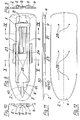
- FIGs. 1 to 7 of the drawing show a generally designated 1 Ironing table, which consists essentially of an ironing board 2 and a folding Support frame 3 consists.
- the ironing board 2 - the in the drawing without textile ironing board cover and possibly existing editions such as insects and / or heat radiation reflective film or the like.
- is shown - is formed by a shaped body 4, which is made in one piece is and consists of a rigid foam.
- As starting material for the rigid foam is advantageous polypropylene used, being for the process for the production of the molding - as already explained above - two alternatives consist.
- To achieve sufficient strength and resilience is the density of the rigid foam - at a thickness of the shaped body. 4 in the order of about 50 mm - appropriate to a value in the Adjusted magnitude of about 60g / l and has a closed-celled Structure.
- the molded body 4 depressions or elevations 5, 6, 7, 8 and 9 or 10, 11 (see Figs. 8 to 10) for receiving elements of the support frame 3 of the ironing board 1.
- These elements are first Guide and bearing rails 12, 13 for guiding or storage of the two 14 and 15 designated pivotable legs of the support frame. 3 Then belong to these elements, the legs 14, 15, up to relatively short areas of their closed with a pedestal 16 and 17 respectively free ends at least largely or predominantly below the through denoted by 18 and 19, the outer contour of the underside of the molding 4 significantly determining areas are.
- the molded body 4 has the convenient handling of the ironing board. 1 serving integrated grip areas 23, 24, which are approximately in the middle of the near one or the other, designated 25 and 26 longitudinal side of the Shaped body 4 are provided.
- locking means for the base 16 are obvious on the molded body 4 Area of the supporting leg 14 integrated provided by the two mentioned elevations 10, 11 are formed. These surveys are like that shaped and dimensioned that they the relevant, designated 27 area the supporting leg 14 in the folded state of the support frame 3 or the ironing board 1 fixed and slightly resilient over the diameter of the tubular Include leg 14 to a certain extent encompassing, so that thereby a locking effect is achieved. - Also for the concerned Ends of the other, formed by two tubes pillar 15 may be a similar locking be provided.
- mounting holes 28 are provided, which appropriate, not Specified mounting holes or tapped holes in the two guide and bearing rails 12, 13 of the support frame 3 are opposite.
- the guide and bearing rails 12, 13 are by means of a connecting part 29 to a total of U-shaped and preferably made of metal existing frame part connected together.
- the mentioned Fastening openings are from the top 30 denoted Shaped 4 forth accessible; However, it is also possible to appropriate Fasteners such as cup-shaped threaded sleeves in Shaped to provide only from the bottom of the designated 31 of Form body 4 forth are accessible and preferably by lathering are integrated into the molded body 4.
- the support frame 3 for further improving the handling and operating characteristics of the ironing board 1 one or more, unspecified springs on, on the one hand to the guide and bearing rails 12, 13 and on the other hand at one and / or the other of two legs 14 and 15 of the support frame 3 attack.
- these springs are designed as torsion springs.
Landscapes
- Engineering & Computer Science (AREA)
- Textile Engineering (AREA)
- Irons (AREA)
- Laminated Bodies (AREA)
- Gloves (AREA)
- Rigid Containers With Two Or More Constituent Elements (AREA)
- Chemical And Physical Treatments For Wood And The Like (AREA)
- Diaphragms For Electromechanical Transducers (AREA)
Abstract
Description
- Fig. 1
- einen Bügeltisch mit einer erfindungsgemäßen Bügeltischplatte im ausgeklappten Zustand des Stützgestells und in perspektivischer Darstellung,
- Fig. 2
- den Bügeltisch nach Fig. 1 in einer Seitenansicht,
- Fig. 3
- den Bügeltisch nach den Fig. 1 und 2 in einer Aufsicht auf die Oberseite der Bügeltischplatte,
- Fig. 4
- den Bügeltisch nach den Fig. 1 bis 3, jedoch im zusammengeklappten Zustand des Stützgestells, in perspektivischer Darstellung,
- Fig. 5
- den Bügeltisch nach Fig. 4 in einer Aufsicht auf die Unterseite der Bügeltischplatte,
- Fig. 6
- den Bügeltisch nach den Fig. 4 und 5 in einer Seitenansicht,
- Fig. 7
- den Bügeltisch nach den Fig. 4 bis 6 in einer Aufsicht auf die Oberseite der Bügeltischplatte,
- Fig. 8
- den für die erfindungsgemäße Bügeltischplatte des Bügeltisches nach den Fig. 1 bis 7 vorgesehenen Formkörper in einer Aufsicht auf die Unterseite dieses Formkörpers,
- Fig. 9
- den Formkörper nach Fig. 8 in der Vorderansicht im Schnitt entsprechend Schnittlinie IX-IX in Fig. 8,
- Fig. 10
- den Formkörper nach den Fig. 8 und 9 in der Rückansicht im Schnitt entsprechend Schnittlinie X-X in Fig. 8,
- Fig. 11
- den Formkörper nach den Fig. 8 bis 10 in einer Seitenansicht, und
- Fig. 12
- den Formkörper nach den Fig. 8 bis 11 in der Aufsicht.
- 1
- Bügeltisch
- 2
- Bügeltischplatte
- 3
- Stützgestell
- 4
- Formkörper
- 5
- Vertiefung
- 6
- Vertiefung
- 7
- Vertiefung
- 8
- Vertiefung
- 9
- Vertiefung
- 10
- Erhebung
- 11
- Erhebung
- 12
- Führungs- und Lagerschienen
- 13
- Führungs- und Lagerschienen
- 14
- Standbein
- 15
- Standbein
- 16
- Standfüß
- 17
- Standfuß
- 18
- Flächenbereich
- 19
- Flächenbereich
- 20
- Schwenkachse
- 21
- Schwenkachse
- 22
- Schwenkachse
- 23
- Griffbereich
- 24
- Griffbereich
- 25
- Längsseite
- 26
- Längsseite
- 27
- Bereich
- 28
- Befestigungsöffnungen
- 29
- Verbindungsteil
- 30
- Oberseite
- 31
- Unterseite
Claims (23)
- Bügeltischplatte (2) aus Kunststoff, dadurch gekennzeichnet, dass die Bügeltischplatte (2) ein aus einem Hartschaumstoff bestehender einteiliger Formkörper (4) ist.
- Bügeltischplatte nach Anspruch 1, dadurch gekennzeichnet, dass als Hartschaumstoff ein geschlossen-zelliger Schaumstoff vorgesehen ist.
- Bügeltischplatte nach Anspruch 2, dadurch gekennzeichnet, dass als Hartschaumstoff expandiertes Polypropylen vorgesehen ist.
- Bügeltischplatte nach Anspruch 2, dadurch gekennzeichnet, dass der Formkörper (4) homogen geschäumt ist.
- Bügeltischplatte nach Anspruch 2, dadurch gekennzeichnet, dass der Formkörper (4) aus getempertem/gesintertem Schaumstoffgranulat besteht.
- Bügeltischplatte nach Anspruch 1, dadurch gekennzeichnet, dass die Oberseite (30) des Formkörpers (4) Wärmestrahlung reflektierend beschichtet ist.
- Bügeltischplatte nach Anspruch 1, dadurch gekennzeichnet, dass in den Formkörper (4) Führungs- und/oder Lagermittel (Führungs- und Lagerschienen (12, 13) für das Stützgestell (3) eines Bügeltisches (1) eingeschäumt sind.
- Bügeltischplatte nach Anspruch 1, dadurch gekennzeichnet, dass dem Formkörper (4) Führungs- und/oder Lagermittel (Führungs- und Lagerschienen 12, 13) für das Stützgestell (3) eines Bügeltisches (1) zugeordnet sind, die mit dem Formkörper (4) verbindbar sind.
- Bügeltischplatte nach Anspruch 7 oder 8, dadurch gekennzeichnet, dass die Führungs- und/oder Lagermittel (Führungs- und Lagerschienen 12, 13) für das Stützgestell (3) eines Bügeltisches (1) zumindest zu einem erheblichen Anteil unterhalb der Außenkontur der Unterseite (31) des Formkörpers (4) liegen.
- Bügeltischplatte nach Anspruch 1, dadurch gekennzeichnet, dass der Formkörper (4) auf seiner Unterseite (31) Vertiefungen und/oder Erhebungen oder dgl. (5 bis 9 bzw. 10, 11) zum Aufnehmen von Elementen (Standbeine 14, 15) des Stützgestells (3) eines Bügeltisches (1) aufweist.
- Bügeltischplatte nach Anspruch 1, dadurch gekennzeichnet, dass der Formkörper (4) von seiner Oberseite (30) her zugängliche Befestigungsöffnungen (28) für ein auf seiner Unterseite (31) befestigbares Stützgestell (3) eines Bügeltisches (1) aufweist.
- Bügeltischplatte nach Anspruch 11, dadurch gekennzeichnet, dass der Formkörper (4) um die Befestigungsöffnungen (28) herum verstärkt ist.
- Bügeltisch (1), dadurch gekennzeichnet, dass er eine Bügeltischplatte (2) nach einem der Ansprüche 1 bis 12 aufweist.
- Bügeltisch (1) nach Anspruch 13, dadurch gekennzeichnet, dass die Führungs- und/oder Lagermittel (Führungs- und Lagerschienen 12, 13) für das Stützgestell (3) des Bügeltisches (1) als U-förmiges Rahmenteil (Führungs- und Lagerschienen 12, 13 sowie Verbindungsteil (29) ausgebildet sind, dessen beide in Längsrichtung der Bügeltischplatte (2) sich erstreckenden freien Schenkel Führungsund Lagerschienen (12, 13) für die oberen Enden des einen, von zwei Rohren gebildeten Standbeines (15) des Stützgestells (3) bilden und dessen die erwähnten beiden Schenkel miteinander verbindendes Verbindungsteil (29) die Schwenkachse für das andere Standbein (14) aufnimmt oder bildet.
- Bügeltisch nach Anspruch 14, dadurch gekennzeichnet, dass das U-förmige Rahmenteil (Führungs- und Lagerschienen 12, 13 sowie Verbindungsteil 29) aus Metall besteht.
- Bügeltisch nach Anspruch 14, dadurch gekennzeichnet, dass das Stützgestell (3) eine oder mehrere Federn aufweist, die einerseits an den Führungs- und/oder Lagermitteln (Führungs- und Lagerschienen 12, 13) und andererseits an dem einem und/oder dem anderen der beiden Standbeine (14, 15) des Stützgestells (3) angreifen.
- Bügeltisch nach Anspruch 16, dadurch gekennzeichnet, dass die Federn Torsionsfedern sind.
- Bügeltisch nach Anspruch 13, dadurch gekennzeichnet, dass der Formkörper (4) integrierte Rastmittel (Erhebungen 10, 11) für Bereiche der Standbeine (14, 15) des Stützgestells aufweist.
- Bügeltisch nach Anspruch 18, dadurch gekennzeichnet, dass die Rastmittel (Erhebungen 10, 11) in der Nähe des einen bzw. des anderen Endes der Bügeltischplatte (2) bzw. des Formkörpers (4) des Bügeltisches (1) vorgesehen sind.
- Bügeltisch nach Anspruch 13, dadurch gekennzeichnet, dass der Formkörper (4) integrierte Griffbereiche (23, 24) aufweist.
- Bügeltisch nach Anspruch 20, dadurch gekennzeichnet, dass die Griffbereiche (23, 24) etwa mittig in der Nähe der einen bzw. der anderen Längsseite (25, 26) der Bügeltischplatte (2) bzw. des Formkörpers (4) vorgesehen sind.
- Verfahren zur Herstellung des Formkörpers nach Anspruch 1, dadurch gekennzeichnet, dass der Formkörper (4) in der Form des Formwerkzeuges aus dem Kunststoff, z.B. Polypropylen, homogen aufgeschäumt wird.
- Verfahren zur Herstellung des Formkörpers nach Anspruch 1, dadurch gekennzeichnet, dass der Formkörper (4) aus Schaumstoff-Granulat hergestellt wird, das in der Form des Formwerkzeuges verpresst und in einem folgenden Arbeitsgang getempert/gesintert wird.
Applications Claiming Priority (2)
| Application Number | Priority Date | Filing Date | Title |
|---|---|---|---|
| DE10162734A DE10162734B4 (de) | 2001-12-20 | 2001-12-20 | Bügeltischplatte und Bügeltisch |
| DE10162734 | 2001-12-20 |
Publications (3)
| Publication Number | Publication Date |
|---|---|
| EP1321567A2 true EP1321567A2 (de) | 2003-06-25 |
| EP1321567A3 EP1321567A3 (de) | 2004-01-02 |
| EP1321567B1 EP1321567B1 (de) | 2006-05-31 |
Family
ID=7710021
Family Applications (1)
| Application Number | Title | Priority Date | Filing Date |
|---|---|---|---|
| EP02027265A Expired - Lifetime EP1321567B1 (de) | 2001-12-20 | 2002-12-06 | Bügeltischplatte mit Bügeltisch |
Country Status (5)
| Country | Link |
|---|---|
| US (1) | US6834450B2 (de) |
| EP (1) | EP1321567B1 (de) |
| AT (1) | ATE328147T1 (de) |
| DE (2) | DE10162734B4 (de) |
| ES (1) | ES2262752T3 (de) |
Cited By (3)
| Publication number | Priority date | Publication date | Assignee | Title |
|---|---|---|---|---|
| EP1944405A3 (de) * | 2007-01-09 | 2010-07-28 | Leifheit AG | Bügeltischplatte |
| WO2013038317A1 (en) * | 2011-09-13 | 2013-03-21 | Koninklijke Philips Electronics N.V. | Ironing board cover |
| EP2336422B1 (de) * | 2009-12-17 | 2019-10-23 | Leifheit AG | Dampfbügeltisch |
Families Citing this family (15)
| Publication number | Priority date | Publication date | Assignee | Title |
|---|---|---|---|---|
| USD520207S1 (en) * | 2002-11-21 | 2006-05-02 | Leifheit Ag | Ironing board with stand |
| US20040216337A1 (en) * | 2003-04-30 | 2004-11-04 | Harrison Sharon Jean | Covered pressing board top, covered portable pressing board, stand, and tote bag |
| US7225745B2 (en) * | 2004-05-10 | 2007-06-05 | Home Products International, Inc. | Free standing ironing board |
| EP1690977A3 (de) * | 2005-02-10 | 2006-08-30 | Keter Plastic Ltd. | Bügeltisch |
| US7131223B2 (en) * | 2005-03-22 | 2006-11-07 | Bajer Design & Marketing, Inc. | Portable ironing pad assembly |
| DE102005013167A1 (de) * | 2005-03-22 | 2006-09-28 | Hailo-Werk Rudolf Loh Gmbh & Co. Kg | Dampfbügeltisch |
| US20100043260A1 (en) * | 2005-07-07 | 2010-02-25 | Koninklijke Philips Electronics N.V. | Method for operating an active ironing board |
| US20070044350A1 (en) * | 2005-08-31 | 2007-03-01 | Ching-Song Tang | Ironing board |
| CN2913422Y (zh) * | 2006-03-06 | 2007-06-20 | 何玉莲 | 一种烫衣板用塑料板面 |
| DE102006054950B3 (de) | 2006-11-22 | 2008-05-21 | Leifheit Ag | Zusammenklappbares Standgestell für einen Bügeltisch |
| GB0916384D0 (en) | 2009-09-18 | 2009-10-28 | Vale Mill Rochdale Ltd | Ironing board |
| USD674160S1 (en) * | 2010-01-25 | 2013-01-08 | Vale Mill (Rochdale) Limited | Ironing board |
| AU345279S (en) * | 2012-04-16 | 2012-10-31 | Calor Sa | Ironing board |
| USD706006S1 (en) * | 2013-02-28 | 2014-05-27 | Pro-Mart Industries, Inc. | Ironing board |
| CA3178171A1 (en) * | 2020-05-08 | 2021-11-11 | Colin Andrew DOWDLE | Adjustable and collapsible desk |
Family Cites Families (26)
| Publication number | Priority date | Publication date | Assignee | Title |
|---|---|---|---|---|
| BE625551A (de) * | ||||
| US2912775A (en) * | 1954-09-07 | 1959-11-17 | Arvin Ind Inc | Ironing tables |
| US3206881A (en) * | 1962-11-05 | 1965-09-21 | George H Kleinsorge | Ironing table |
| GB1017572A (en) * | 1963-04-22 | 1966-01-19 | Robert Stanley Alderton | Improved ironing board |
| US3268636A (en) * | 1963-07-01 | 1966-08-23 | Union Carbide Corp | Method and apparatus for injection molding foamed plastic articles |
| US3702100A (en) * | 1971-04-05 | 1972-11-07 | Menasha Corp | Molded pallet |
| DE7224033U (de) * | 1972-06-27 | 1972-10-12 | Heraeus-Christ Gmbh | Kleinzentrifuge |
| US3938081A (en) * | 1973-05-03 | 1976-02-10 | Kirk Robert T | Circuitry for preventing the use of erroneous data |
| DE8006001U1 (de) * | 1980-03-05 | 1980-05-29 | Heinrich Struewer Metallwarenfabrik, 4760 Werl | Zusammenklappbarer buegeltisch |
| US4360984A (en) * | 1981-07-27 | 1982-11-30 | Ruttenberg Reid W | Portable ironing pad |
| US4579872A (en) * | 1985-05-06 | 1986-04-01 | The Dow Chemical Company | Uniform minimization of plastic foam cell size |
| US4740032A (en) * | 1985-07-22 | 1988-04-26 | Phyllis Olsen | Compact and lightweight bench with removable parts |
| USRE34450E (en) * | 1988-01-19 | 1993-11-23 | Sorai Saito | Convex pressing board with surface projecting |
| CH672152A5 (en) * | 1988-02-18 | 1989-10-31 | Emma Rotach | Ironing cover - made of plastic foam slab wrapped in textile fabric |
| GB8928447D0 (en) * | 1989-12-16 | 1990-02-21 | Bernstein David S | Ironing apparatus |
| JPH068878Y2 (ja) * | 1990-05-15 | 1994-03-09 | 素頼 齊藤 | 分離型アイロン台及びこの分離型アイロン台を用いたアイロン装置 |
| US5329710A (en) * | 1992-10-15 | 1994-07-19 | Huddleston Leona B | Folding table top for an ironing board |
| JPH0737100U (ja) * | 1993-12-24 | 1995-07-11 | 素頼 齋藤 | アイロン台 |
| US5572811A (en) * | 1995-01-06 | 1996-11-12 | Lehrman; David | Ironing board with telescoping storage racks |
| US5706593A (en) * | 1997-02-06 | 1998-01-13 | Allard; Alice J. | Compact ironing board securable to an edge |
| EP1002895B1 (de) * | 1998-11-18 | 2006-12-20 | LEIFHEIT Aktiengesellschaft | Bügelauflage, Bügeltischplatte und Bügeltisch |
| US6010185A (en) * | 1999-01-14 | 2000-01-04 | Petersen; Chris C. | Picnic table |
| US6349490B1 (en) * | 1999-05-17 | 2002-02-26 | Leifheit Ag | Ironing board cover set and an ironing board top or ironing board using the cover set |
| US6026601A (en) * | 1999-05-25 | 2000-02-22 | Kiel; Walter J. | Ironing board adapted to vertical surface |
| DE19929289A1 (de) * | 1999-06-25 | 2000-12-28 | Leifheit Ag | Bügeltisch |
| DE10042978C2 (de) * | 1999-10-07 | 2002-02-28 | Kerst Deko Objekte Gerhard Ker | Platte bzw. mehrschichtiges Element aus Hartschaum |
-
2001
- 2001-12-20 DE DE10162734A patent/DE10162734B4/de not_active Expired - Fee Related
-
2002
- 2002-12-06 ES ES02027265T patent/ES2262752T3/es not_active Expired - Lifetime
- 2002-12-06 DE DE50206982T patent/DE50206982D1/de not_active Expired - Lifetime
- 2002-12-06 EP EP02027265A patent/EP1321567B1/de not_active Expired - Lifetime
- 2002-12-06 AT AT02027265T patent/ATE328147T1/de not_active IP Right Cessation
- 2002-12-20 US US10/325,156 patent/US6834450B2/en not_active Expired - Lifetime
Cited By (4)
| Publication number | Priority date | Publication date | Assignee | Title |
|---|---|---|---|---|
| EP1944405A3 (de) * | 2007-01-09 | 2010-07-28 | Leifheit AG | Bügeltischplatte |
| EP2336422B1 (de) * | 2009-12-17 | 2019-10-23 | Leifheit AG | Dampfbügeltisch |
| WO2013038317A1 (en) * | 2011-09-13 | 2013-03-21 | Koninklijke Philips Electronics N.V. | Ironing board cover |
| US9222214B2 (en) | 2011-09-13 | 2015-12-29 | Koninklijke Philips N.V. | Ironing board cover |
Also Published As
| Publication number | Publication date |
|---|---|
| EP1321567A3 (de) | 2004-01-02 |
| EP1321567B1 (de) | 2006-05-31 |
| ES2262752T3 (es) | 2006-12-01 |
| US20030121186A1 (en) | 2003-07-03 |
| US6834450B2 (en) | 2004-12-28 |
| DE10162734A1 (de) | 2003-07-17 |
| DE10162734B4 (de) | 2007-11-08 |
| ATE328147T1 (de) | 2006-06-15 |
| DE50206982D1 (de) | 2006-07-06 |
Similar Documents
| Publication | Publication Date | Title |
|---|---|---|
| EP1321567B1 (de) | Bügeltischplatte mit Bügeltisch | |
| DE60007342T2 (de) | Verfahren zur herstellung eines dachhimmels mit integriertem, energieabsorbierendem schaum | |
| DE2632355A1 (de) | Mittelarmlehne fuer wenigstens zwei sitze | |
| EP1927493B1 (de) | Spriegelanordnung für ein Cabriolet-Fahrzeug | |
| EP3536191B1 (de) | Einstellbarer tisch | |
| EP2063015B1 (de) | Bügelunterlage | |
| WO2020007621A1 (de) | Fahrradsattel sowie verfahren zur herstellung eines polsterelements für einen fahrradsattel | |
| EP1680322B1 (de) | Sitz, insbesondere fluggastsitz | |
| EP1002895B1 (de) | Bügelauflage, Bügeltischplatte und Bügeltisch | |
| DE202011108494U1 (de) | Klappbares Möbelstück | |
| DE1429284A1 (de) | Sitzpolster | |
| DE102005055053B4 (de) | Bügeltisch und Anordnung zum Bügeln von Wäsche | |
| DE10209561A1 (de) | Sitz, insbesondere Rücksitz eines Kraftfahrzeugs, sowie zur Verwendung bei einem derartigen Sitz geeigneter Polsterbezug | |
| EP1944405B1 (de) | Bügeltischplatte | |
| EP1581379B9 (de) | Verfahren zum herstellen eines formteils aus einem textilen flächengebilde | |
| DE10011453B4 (de) | Duschvorrichtung | |
| AT253163B (de) | Sitzschale | |
| DE102004050851B3 (de) | Nackenstütze für einen Stuhl mit Rückenlehne und Stuhl mit einer derartigen, auf dem oberen Rand der Rückenlehne befestigbaren Nackenstütze | |
| DE29601539U1 (de) | Klappbarer Wäschetrockner | |
| DE7525530U (de) | Klappsitz | |
| DE4109077C2 (de) | ||
| AT411138B (de) | Stuhl mit einer sitzfläche und einer rückenlehne | |
| EP2336422B1 (de) | Dampfbügeltisch | |
| WO2002033182A1 (de) | Spüle und verfahren zum herstellen einer spüle | |
| DE202025100415U1 (de) | Multifunktionaler klappbarer Werkzeugwagen mit Klappsitz |
Legal Events
| Date | Code | Title | Description |
|---|---|---|---|
| PUAI | Public reference made under article 153(3) epc to a published international application that has entered the european phase |
Free format text: ORIGINAL CODE: 0009012 |
|
| AK | Designated contracting states |
Designated state(s): AT BE BG CH CY CZ DE DK EE ES FI FR GB GR IE IT LI LU MC NL PT SE SI SK TR |
|
| AX | Request for extension of the european patent |
Extension state: AL LT LV MK RO |
|
| PUAL | Search report despatched |
Free format text: ORIGINAL CODE: 0009013 |
|
| 17P | Request for examination filed |
Effective date: 20031004 |
|
| AK | Designated contracting states |
Kind code of ref document: A3 Designated state(s): AT BE BG CH CY CZ DE DK EE ES FI FR GB GR IE IT LI LU MC NL PT SE SI SK TR |
|
| AX | Request for extension of the european patent |
Extension state: AL LT LV MK RO |
|
| 17Q | First examination report despatched |
Effective date: 20040526 |
|
| AKX | Designation fees paid |
Designated state(s): AT BE BG CH CY CZ DE DK EE ES FI FR GB GR IE IT LI LU MC NL PT SE SI SK TR |
|
| GRAP | Despatch of communication of intention to grant a patent |
Free format text: ORIGINAL CODE: EPIDOSNIGR1 |
|
| GRAS | Grant fee paid |
Free format text: ORIGINAL CODE: EPIDOSNIGR3 |
|
| GRAA | (expected) grant |
Free format text: ORIGINAL CODE: 0009210 |
|
| AK | Designated contracting states |
Kind code of ref document: B1 Designated state(s): AT BE BG CH CY CZ DE DK EE ES FI FR GB GR IE IT LI LU MC NL PT SE SI SK TR |
|
| PG25 | Lapsed in a contracting state [announced via postgrant information from national office to epo] |
Ref country code: IE Free format text: LAPSE BECAUSE OF FAILURE TO SUBMIT A TRANSLATION OF THE DESCRIPTION OR TO PAY THE FEE WITHIN THE PRESCRIBED TIME-LIMIT Effective date: 20060531 Ref country code: FI Free format text: LAPSE BECAUSE OF FAILURE TO SUBMIT A TRANSLATION OF THE DESCRIPTION OR TO PAY THE FEE WITHIN THE PRESCRIBED TIME-LIMIT Effective date: 20060531 Ref country code: SI Free format text: LAPSE BECAUSE OF FAILURE TO SUBMIT A TRANSLATION OF THE DESCRIPTION OR TO PAY THE FEE WITHIN THE PRESCRIBED TIME-LIMIT Effective date: 20060531 Ref country code: SK Free format text: LAPSE BECAUSE OF FAILURE TO SUBMIT A TRANSLATION OF THE DESCRIPTION OR TO PAY THE FEE WITHIN THE PRESCRIBED TIME-LIMIT Effective date: 20060531 Ref country code: CZ Free format text: LAPSE BECAUSE OF FAILURE TO SUBMIT A TRANSLATION OF THE DESCRIPTION OR TO PAY THE FEE WITHIN THE PRESCRIBED TIME-LIMIT Effective date: 20060531 |
|
| REG | Reference to a national code |
Ref country code: GB Ref legal event code: FG4D Free format text: NOT ENGLISH Ref country code: CH Ref legal event code: NV Representative=s name: ISLER & PEDRAZZINI AG Ref country code: CH Ref legal event code: EP |
|
| GBT | Gb: translation of ep patent filed (gb section 77(6)(a)/1977) |
Effective date: 20060531 |
|
| REG | Reference to a national code |
Ref country code: IE Ref legal event code: FG4D Free format text: LANGUAGE OF EP DOCUMENT: GERMAN |
|
| REF | Corresponds to: |
Ref document number: 50206982 Country of ref document: DE Date of ref document: 20060706 Kind code of ref document: P |
|
| PG25 | Lapsed in a contracting state [announced via postgrant information from national office to epo] |
Ref country code: DK Free format text: LAPSE BECAUSE OF FAILURE TO SUBMIT A TRANSLATION OF THE DESCRIPTION OR TO PAY THE FEE WITHIN THE PRESCRIBED TIME-LIMIT Effective date: 20060831 Ref country code: SE Free format text: LAPSE BECAUSE OF FAILURE TO SUBMIT A TRANSLATION OF THE DESCRIPTION OR TO PAY THE FEE WITHIN THE PRESCRIBED TIME-LIMIT Effective date: 20060831 |
|
| PG25 | Lapsed in a contracting state [announced via postgrant information from national office to epo] |
Ref country code: PT Free format text: LAPSE BECAUSE OF FAILURE TO SUBMIT A TRANSLATION OF THE DESCRIPTION OR TO PAY THE FEE WITHIN THE PRESCRIBED TIME-LIMIT Effective date: 20061031 |
|
| REG | Reference to a national code |
Ref country code: ES Ref legal event code: FG2A Ref document number: 2262752 Country of ref document: ES Kind code of ref document: T3 |
|
| PG25 | Lapsed in a contracting state [announced via postgrant information from national office to epo] |
Ref country code: BE Free format text: LAPSE BECAUSE OF NON-PAYMENT OF DUE FEES Effective date: 20061231 Ref country code: MC Free format text: LAPSE BECAUSE OF NON-PAYMENT OF DUE FEES Effective date: 20061231 |
|
| ET | Fr: translation filed | ||
| REG | Reference to a national code |
Ref country code: IE Ref legal event code: FD4D |
|
| PLBE | No opposition filed within time limit |
Free format text: ORIGINAL CODE: 0009261 |
|
| STAA | Information on the status of an ep patent application or granted ep patent |
Free format text: STATUS: NO OPPOSITION FILED WITHIN TIME LIMIT |
|
| 26N | No opposition filed |
Effective date: 20070301 |
|
| REG | Reference to a national code |
Ref country code: CH Ref legal event code: PCAR Free format text: ISLER & PEDRAZZINI AG;POSTFACH 1772;8027 ZUERICH (CH) |
|
| BERE | Be: lapsed |
Owner name: LEIFHEIT A.G. Effective date: 20061231 |
|
| PG25 | Lapsed in a contracting state [announced via postgrant information from national office to epo] |
Ref country code: AT Free format text: LAPSE BECAUSE OF NON-PAYMENT OF DUE FEES Effective date: 20061206 |
|
| PG25 | Lapsed in a contracting state [announced via postgrant information from national office to epo] |
Ref country code: GR Free format text: LAPSE BECAUSE OF FAILURE TO SUBMIT A TRANSLATION OF THE DESCRIPTION OR TO PAY THE FEE WITHIN THE PRESCRIBED TIME-LIMIT Effective date: 20060901 |
|
| PG25 | Lapsed in a contracting state [announced via postgrant information from national office to epo] |
Ref country code: BG Free format text: LAPSE BECAUSE OF FAILURE TO SUBMIT A TRANSLATION OF THE DESCRIPTION OR TO PAY THE FEE WITHIN THE PRESCRIBED TIME-LIMIT Effective date: 20060831 Ref country code: EE Free format text: LAPSE BECAUSE OF FAILURE TO SUBMIT A TRANSLATION OF THE DESCRIPTION OR TO PAY THE FEE WITHIN THE PRESCRIBED TIME-LIMIT Effective date: 20060531 |
|
| PG25 | Lapsed in a contracting state [announced via postgrant information from national office to epo] |
Ref country code: TR Free format text: LAPSE BECAUSE OF FAILURE TO SUBMIT A TRANSLATION OF THE DESCRIPTION OR TO PAY THE FEE WITHIN THE PRESCRIBED TIME-LIMIT Effective date: 20060531 Ref country code: LU Free format text: LAPSE BECAUSE OF NON-PAYMENT OF DUE FEES Effective date: 20061206 |
|
| PG25 | Lapsed in a contracting state [announced via postgrant information from national office to epo] |
Ref country code: CY Free format text: LAPSE BECAUSE OF FAILURE TO SUBMIT A TRANSLATION OF THE DESCRIPTION OR TO PAY THE FEE WITHIN THE PRESCRIBED TIME-LIMIT Effective date: 20060531 |
|
| PGFP | Annual fee paid to national office [announced via postgrant information from national office to epo] |
Ref country code: DE Payment date: 20150120 Year of fee payment: 13 |
|
| REG | Reference to a national code |
Ref country code: FR Ref legal event code: PLFP Year of fee payment: 14 |
|
| REG | Reference to a national code |
Ref country code: DE Ref legal event code: R119 Ref document number: 50206982 Country of ref document: DE |
|
| PG25 | Lapsed in a contracting state [announced via postgrant information from national office to epo] |
Ref country code: DE Free format text: LAPSE BECAUSE OF NON-PAYMENT OF DUE FEES Effective date: 20160701 |
|
| REG | Reference to a national code |
Ref country code: FR Ref legal event code: PLFP Year of fee payment: 15 |
|
| PGFP | Annual fee paid to national office [announced via postgrant information from national office to epo] |
Ref country code: CH Payment date: 20161025 Year of fee payment: 15 Ref country code: NL Payment date: 20161207 Year of fee payment: 15 Ref country code: GB Payment date: 20161125 Year of fee payment: 15 |
|
| PGFP | Annual fee paid to national office [announced via postgrant information from national office to epo] |
Ref country code: ES Payment date: 20161215 Year of fee payment: 15 |
|
| REG | Reference to a national code |
Ref country code: FR Ref legal event code: PLFP Year of fee payment: 16 |
|
| PGFP | Annual fee paid to national office [announced via postgrant information from national office to epo] |
Ref country code: FR Payment date: 20171120 Year of fee payment: 16 |
|
| PGFP | Annual fee paid to national office [announced via postgrant information from national office to epo] |
Ref country code: IT Payment date: 20171218 Year of fee payment: 16 |
|
| REG | Reference to a national code |
Ref country code: CH Ref legal event code: PL |
|
| REG | Reference to a national code |
Ref country code: NL Ref legal event code: MM Effective date: 20180101 |
|
| GBPC | Gb: european patent ceased through non-payment of renewal fee |
Effective date: 20171206 |
|
| PG25 | Lapsed in a contracting state [announced via postgrant information from national office to epo] |
Ref country code: NL Free format text: LAPSE BECAUSE OF NON-PAYMENT OF DUE FEES Effective date: 20180101 |
|
| PG25 | Lapsed in a contracting state [announced via postgrant information from national office to epo] |
Ref country code: CH Free format text: LAPSE BECAUSE OF NON-PAYMENT OF DUE FEES Effective date: 20171231 Ref country code: GB Free format text: LAPSE BECAUSE OF NON-PAYMENT OF DUE FEES Effective date: 20171206 Ref country code: LI Free format text: LAPSE BECAUSE OF NON-PAYMENT OF DUE FEES Effective date: 20171231 |
|
| REG | Reference to a national code |
Ref country code: ES Ref legal event code: FD2A Effective date: 20190702 |
|
| PG25 | Lapsed in a contracting state [announced via postgrant information from national office to epo] |
Ref country code: ES Free format text: LAPSE BECAUSE OF NON-PAYMENT OF DUE FEES Effective date: 20171207 |
|
| PG25 | Lapsed in a contracting state [announced via postgrant information from national office to epo] |
Ref country code: IT Free format text: LAPSE BECAUSE OF NON-PAYMENT OF DUE FEES Effective date: 20181206 Ref country code: FR Free format text: LAPSE BECAUSE OF NON-PAYMENT OF DUE FEES Effective date: 20181231 |