EP1321284B1 - Verfahren zur Herstellung eines vulkanisierten gekrümmten Schlauchs in einer Negativform unter Verwendung einer temporären Schlauchummantelung - Google Patents
Verfahren zur Herstellung eines vulkanisierten gekrümmten Schlauchs in einer Negativform unter Verwendung einer temporären Schlauchummantelung Download PDFInfo
- Publication number
- EP1321284B1 EP1321284B1 EP02022602A EP02022602A EP1321284B1 EP 1321284 B1 EP1321284 B1 EP 1321284B1 EP 02022602 A EP02022602 A EP 02022602A EP 02022602 A EP02022602 A EP 02022602A EP 1321284 B1 EP1321284 B1 EP 1321284B1
- Authority
- EP
- European Patent Office
- Prior art keywords
- mandrel
- hose
- hose blank
- blank
- supporting sheath
- Prior art date
- Legal status (The legal status is an assumption and is not a legal conclusion. Google has not performed a legal analysis and makes no representation as to the accuracy of the status listed.)
- Expired - Lifetime
Links
- 238000000034 method Methods 0.000 title claims description 12
- 238000004519 manufacturing process Methods 0.000 title claims description 9
- 238000004073 vulcanization Methods 0.000 claims description 25
- 229920001971 elastomer Polymers 0.000 claims description 7
- 239000000463 material Substances 0.000 claims description 7
- 239000000806 elastomer Substances 0.000 claims description 3
- 238000012546 transfer Methods 0.000 claims description 3
- 238000010438 heat treatment Methods 0.000 claims description 2
- NLHHRLWOUZZQLW-UHFFFAOYSA-N Acrylonitrile Chemical compound C=CC#N NLHHRLWOUZZQLW-UHFFFAOYSA-N 0.000 claims 1
- 239000005062 Polybutadiene Substances 0.000 claims 1
- 229920002857 polybutadiene Polymers 0.000 claims 1
- 239000010410 layer Substances 0.000 description 4
- 239000004033 plastic Substances 0.000 description 3
- 239000011241 protective layer Substances 0.000 description 3
- 239000007767 bonding agent Substances 0.000 description 2
- 230000000295 complement effect Effects 0.000 description 2
- 238000011161 development Methods 0.000 description 2
- 230000018109 developmental process Effects 0.000 description 2
- 238000003780 insertion Methods 0.000 description 2
- 230000037431 insertion Effects 0.000 description 2
- 229920001169 thermoplastic Polymers 0.000 description 2
- 239000012815 thermoplastic material Substances 0.000 description 2
- 239000004677 Nylon Substances 0.000 description 1
- 239000002318 adhesion promoter Substances 0.000 description 1
- XAGFODPZIPBFFR-UHFFFAOYSA-N aluminium Chemical compound [Al] XAGFODPZIPBFFR-UHFFFAOYSA-N 0.000 description 1
- 229910052782 aluminium Inorganic materials 0.000 description 1
- 238000005253 cladding Methods 0.000 description 1
- 239000004020 conductor Substances 0.000 description 1
- 238000010924 continuous production Methods 0.000 description 1
- 238000001816 cooling Methods 0.000 description 1
- 238000005336 cracking Methods 0.000 description 1
- 238000005520 cutting process Methods 0.000 description 1
- 230000006735 deficit Effects 0.000 description 1
- 230000001419 dependent effect Effects 0.000 description 1
- 230000000694 effects Effects 0.000 description 1
- 239000000835 fiber Substances 0.000 description 1
- 239000011888 foil Substances 0.000 description 1
- 238000013507 mapping Methods 0.000 description 1
- 229920001778 nylon Polymers 0.000 description 1
- 239000006223 plastic coating Substances 0.000 description 1
- 238000002360 preparation method Methods 0.000 description 1
- 230000002040 relaxant effect Effects 0.000 description 1
- 238000004904 shortening Methods 0.000 description 1
- 238000005728 strengthening Methods 0.000 description 1
- 230000008961 swelling Effects 0.000 description 1
- 239000004753 textile Substances 0.000 description 1
- 239000004416 thermosoftening plastic Substances 0.000 description 1
- 230000037303 wrinkles Effects 0.000 description 1
Images
Classifications
-
- B—PERFORMING OPERATIONS; TRANSPORTING
- B29—WORKING OF PLASTICS; WORKING OF SUBSTANCES IN A PLASTIC STATE IN GENERAL
- B29C—SHAPING OR JOINING OF PLASTICS; SHAPING OF MATERIAL IN A PLASTIC STATE, NOT OTHERWISE PROVIDED FOR; AFTER-TREATMENT OF THE SHAPED PRODUCTS, e.g. REPAIRING
- B29C53/00—Shaping by bending, folding, twisting, straightening or flattening; Apparatus therefor
- B29C53/02—Bending or folding
- B29C53/08—Bending or folding of tubes or other profiled members
- B29C53/083—Bending or folding of tubes or other profiled members bending longitudinally, i.e. modifying the curvature of the tube axis
-
- F—MECHANICAL ENGINEERING; LIGHTING; HEATING; WEAPONS; BLASTING
- F16—ENGINEERING ELEMENTS AND UNITS; GENERAL MEASURES FOR PRODUCING AND MAINTAINING EFFECTIVE FUNCTIONING OF MACHINES OR INSTALLATIONS; THERMAL INSULATION IN GENERAL
- F16L—PIPES; JOINTS OR FITTINGS FOR PIPES; SUPPORTS FOR PIPES, CABLES OR PROTECTIVE TUBING; MEANS FOR THERMAL INSULATION IN GENERAL
- F16L11/00—Hoses, i.e. flexible pipes
- F16L11/04—Hoses, i.e. flexible pipes made of rubber or flexible plastics
- F16L11/06—Hoses, i.e. flexible pipes made of rubber or flexible plastics with homogeneous wall
-
- B—PERFORMING OPERATIONS; TRANSPORTING
- B29—WORKING OF PLASTICS; WORKING OF SUBSTANCES IN A PLASTIC STATE IN GENERAL
- B29C—SHAPING OR JOINING OF PLASTICS; SHAPING OF MATERIAL IN A PLASTIC STATE, NOT OTHERWISE PROVIDED FOR; AFTER-TREATMENT OF THE SHAPED PRODUCTS, e.g. REPAIRING
- B29C2793/00—Shaping techniques involving a cutting or machining operation
- B29C2793/0081—Shaping techniques involving a cutting or machining operation before shaping
-
- B—PERFORMING OPERATIONS; TRANSPORTING
- B29—WORKING OF PLASTICS; WORKING OF SUBSTANCES IN A PLASTIC STATE IN GENERAL
- B29C—SHAPING OR JOINING OF PLASTICS; SHAPING OF MATERIAL IN A PLASTIC STATE, NOT OTHERWISE PROVIDED FOR; AFTER-TREATMENT OF THE SHAPED PRODUCTS, e.g. REPAIRING
- B29C35/00—Heating, cooling or curing, e.g. crosslinking or vulcanising; Apparatus therefor
- B29C35/02—Heating or curing, e.g. crosslinking or vulcanizing during moulding, e.g. in a mould
-
- B—PERFORMING OPERATIONS; TRANSPORTING
- B29—WORKING OF PLASTICS; WORKING OF SUBSTANCES IN A PLASTIC STATE IN GENERAL
- B29K—INDEXING SCHEME ASSOCIATED WITH SUBCLASSES B29B, B29C OR B29D, RELATING TO MOULDING MATERIALS OR TO MATERIALS FOR MOULDS, REINFORCEMENTS, FILLERS OR PREFORMED PARTS, e.g. INSERTS
- B29K2021/00—Use of unspecified rubbers as moulding material
-
- B—PERFORMING OPERATIONS; TRANSPORTING
- B29—WORKING OF PLASTICS; WORKING OF SUBSTANCES IN A PLASTIC STATE IN GENERAL
- B29L—INDEXING SCHEME ASSOCIATED WITH SUBCLASS B29C, RELATING TO PARTICULAR ARTICLES
- B29L2009/00—Layered products
-
- B—PERFORMING OPERATIONS; TRANSPORTING
- B29—WORKING OF PLASTICS; WORKING OF SUBSTANCES IN A PLASTIC STATE IN GENERAL
- B29L—INDEXING SCHEME ASSOCIATED WITH SUBCLASS B29C, RELATING TO PARTICULAR ARTICLES
- B29L2023/00—Tubular articles
- B29L2023/004—Bent tubes
Definitions
- the invention relates to a method for producing manifold hoses according to the preamble of claim 1.
- a method for the production of manifold hoses is known from the generic DE 195 27 182 A1. Since the negative mold for inserting and removing the tube blank but must be divisible, it was found that the dividing joints are reflected on the surface of the finished manifold tube, whereby a quality reduction occurs. If the dimensional tolerances between the negative mold and the hose blank deviate from one another in the sense that the hose blank has an undersize, a rugged surface results, on the other hand, the pressure required for vulcanizing the hose blank is not generated homogeneously over the entire hose section, so that the vulcanization is uneven, whereby the reproducibility and quality suffers.
- a wrapping of the hose blank offers no way out of the problem, since on the one hand tight radii of curvature can not be realized and on the other hand, even with large radii of curvature, the support belt on the surface of the manifold hose maps.
- a pre-vulcanization of the still-straight tube blank has proved to be disadvantageous.
- the shape desired by the negative mold is no longer stable after the final vulcanization, since the elbow tube after removal from the negative mold and cooling then assumes a different form of its axis course than was predetermined by the negative mold.
- manifold hoses can be produced by constructing an elastomeric hose blank on a thermoplastic plastic mandrel, encasing it with thermoplastic material, cutting it with the mandrel and vulcanizing it in a negative mold. In order to then be able to separate the plastic coating from the vulcanized hose sections, they are frozen and then peeled off, and finally the dome sections are removed.
- DE-A-1 937 945 describes a method for producing flexible long tubes in which a tube blank is constructed in the usual way on a dome, which for example consists of nylon and can be flexible. This hose blank is then wrapped to ward off harmful external effects with a - expressively thin - protective layer of stretch rubber, and then it is vulcanized. Thereafter, the protective layer is peeled off the hose and the mandrel is removed. As has been shown, it is not possible, by means of a thin protective layer of the type described in this document, to exert from outside a sufficiently high, even vulcanization pressure on the tube blank to thereby reproducibly ensure the homogeneity of the vulcanization of the tube under all circumstances ,
- the invention has for its object to improve the aforementioned method to produce manifold hoses with a reproducible axis defined course at the same time homogeneous vulcanization and smooth outer and inner surfaces.
- the support jacket can be produced in a conventional manner with a smooth inner surface, resulting in a smooth surface contour after vulcanization of the tube blank. Since the support jacket exerts a uniform external pressure on the tube blank during vulcanization, a homogeneous vulcanization is achieved.
- the support jacket follows the desired axis curvature and thus does not affect small radii of curvature. As a result, at any desired radius of curvature of the manifold hoses a homogeneous vulcanization and thus a reproducible quality can be achieved.
- an elastomer is used as the support jacket, the inner diameter of the support jacket in the relaxed state is smaller than the outer diameter of the hose blank, and the support shell is inflated during the Auf ists on the hose blank and relaxed after mounting, after which the inner surface of the support shell to the outer surface of the Hose blanks under pressure applies.
- the mounting of a support jacket is made possible, which has a smaller inner diameter in the relaxed state compared to the outer diameter of the hose blank. Due to the swelling of the support jacket, the fitting is made possible without mechanical stress and impairment of the hose blank. After mounting and relaxing the support jacket is already a uniform Exerted pressure on the tube blank, which can be used in the subsequent vulcanization, once to prevent cracking of the surface of the tube blank and on the other hand to reduce the duration and / or temperature during the vulcanization process.
- a film is extruded onto the mandrel before applying the tube blank, which is connected to the tube blank and remains in the elbow tube after removal of the mandrel.
- This film ensures a wrinkle-free inner surface of the manifold hose and thus reduces flow resistance when using the manifold hoses in pneumatic or hydraulic systems, but also damage the manifold hose due to otherwise possible wrinkles, which can lead to washouts.
- a hollow mandrel is used as the mandrel and the tube blank is also subjected to temperature and pressure from the inside of the mandrel with the carrier medium used for vulcanization.
- the hose blank is preheated with the mandrel located inside and the support jacket before insertion into the negative mold.
- this can be achieved by a heater inserted into the hollow mandrel, z. B. a heating element, or by a hollow mandrel flowing through the heat transfer medium.
- This measure which does not lead to any vulcanization, initially reduces the rigidity of the arrangement of tube blank, the mandrel located inside and the support shell and thus facilitates insertion into the negative mold. If this measure is carried out manually, this represents a considerable relief for the production personnel, who must use a large number of hose blanks in the negative mold in the course of working hours.
- an elastomer material is used as a support jacket.
- an acrylonitrile-butadiene-catschuck which is also known under DIN EN 1629 under the abbreviation NBR.
- This material ensures that at the vulcanization temperatures the necessary external pressure is maintained on the tube blank.
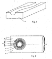
- Fig. 1 half-mold 20 consists of a good heat-conducting material, eg. As aluminum, in which the contour of a manifold to be manufactured hose is milled taking into account the outer surface of an additional support jacket 14. This shape extends over the entire length of the manifold tube to be manufactured.
- a good heat-conducting material eg. As aluminum, in which the contour of a manifold to be manufactured hose is milled taking into account the outer surface of an additional support jacket 14. This shape extends over the entire length of the manifold tube to be manufactured.
- the half-mold 20 is supplemented by a corresponding complementary, not shown in Fig. 1 half-mold 18 which is placed after inserting a hose blank 12 with the mandrel 10 located inside and the over-pulled support casing 14 on the illustrated half-mold 20 and thus the support shell 14th encloses on one side.
- Fig. 2 shows a cross section through the closed mold of two half-molds 18, 20, in which a hose blank 12 is inserted with a mandrel 10 arranged inside and an outer support jacket 14.
- the z. B. may consist of a temperature-resistant plastic, extruded in a continuous process, a film 22. This film 22 later forms the lining of the finished manifold tube.
- an inner layer 24 is extruded from rubber after application of a bonding agent. Subsequently, a bonding agent and a strength member 26 are applied. This can z. B. be a mesh of textile fibers. After applying a further adhesion promoter, an outer layer 28 is extruded from rubber and then cut the endless tube blank together with the plastic village located inside to the predetermined length.
- a support jacket 14 is pulled over the tube blank 12, which extends over the entire length of the cut portion of the tube blank 12. This happens because first the prefabricated support jacket 14 inflated by a pressure medium between the tube blank 12 and support shell 14 while the support shell 14 and the tube blank 12 are axially displaced against each other until the support shell 14 completely covers the tube blank 12. Then, the pressure medium is removed, whereupon the support jacket 14 applies pressure to the tube blank 12.
- tube blank 12 mandrel 10 and support shell 14 is preheated and placed in the half-mold 20.
- a vulcanization takes place in a conventional vulcanization boiler.
- the one Half mold 18 removed and removed the manifold tube in its now final shape of the axis course of the half-mold 20 and the mandrel 10 and the support shell 14 is removed, after which the production is completed.
Landscapes
- Engineering & Computer Science (AREA)
- Mechanical Engineering (AREA)
- General Engineering & Computer Science (AREA)
- Heating, Cooling, Or Curing Plastics Or The Like In General (AREA)
- Moulds For Moulding Plastics Or The Like (AREA)
- Shaping Of Tube Ends By Bending Or Straightening (AREA)
Description
- Die Erfindung betrifft ein Verfahren zur Herstellung von Krümmerschläuchen nach dem Oberbegriff des Anspruchs 1.
- Ein Verfahren zur Herstellung von Krümmerschläuchen ist aus der gattungsbildenden DE 195 27 182 A1 bekannt. Da die Negativform zum Einlegen und Herausnehmen des Schlauchrohlings aber teilbar sein muss, wurde festgestellt, dass sich die Teilungsfugen auf der Oberfläche des fertigen Krümmerschlauches abbilden, wodurch eine Qualitätsminderung eintritt. Weichen die Maßtoleranzen zwischen der Negativform und dem Schlauchrohling in dem Sinne voneinander ab, dass der Schlauchrohling ein Untermaß besitzt, ergibt sich einerseits eine zerklüftete Oberfläche, zum anderen wird der zum Vulkanisieren nötige Druck auf den Schlauchrohling nicht homogen über den gesamten Schlauchabschnitt erzeugt, so dass die Vulkanisation ungleichmäßig ist, wodurch die Reproduzierbarkeit und Qualität leidet. Ein Umwickeln des Schlauchrohlings bietet keinen Ausweg aus der Problematik, da sich einerseits enge Krümmungsradien nicht realisieren lassen und sich andererseits auch bei großen Krümmungsradien das Stützband auf der Oberfläche des Krümmerschlauches abbildet.
- Auch ein Vorvulkanisieren des noch geraden Schlauchrohlings hat sich als nachteilig erwiesen. Die durch die Negativform gewünschte Formgebung ist nach dem Endvulkanisieren nicht mehr beständig, da der Krümmerschlauch nach dem Herausnehmen aus der Negativform und Abkühlen dann eine andere Form seines Achsenverlaufs annimmt als durch die Negativform vorgegeben wurde.
- Bei einem aus der EP-A2-0161 509 bekannten Verfahren zur Herstellung von nicht gekrümmten Schläuchen geht man von einem quasi endlos extrudierten Rohling aus, der dann als Ganzes in einer Ummantelung vulkanisiert wird, die - wie beim bekannten sogenannnten Bleimantel-Verfahren - die Vulkanisationsform bildet, die jedoch nicht aus Blei, sondern aus einem speziellen recycelbaren thermoplastischen Kunststoff besteht. In ähnlicher Weise wird gemäß DE-A-1 965 670 eine Ummantelung des Schlauchrohlings aus einem im plastifizierten Zustand aufgebrachten Kunststoff verwendet.
- Dasselbe Verfahrensprintip ist in der US-A-3 883 384 - und ähnlich auch in der GB-A-1 358 273 - beschrieben, wobei die Ummantelung aus einem flexiblen, nicht vulkanisierbaren Werkstoff gebildet werden soll, der nach der Vulkanisation des Schlauches abgenommen und wiederverwendet werden kann.
- Ferner ist es aus der US-A-4 559 095 bekannt, endlose elastomere Schlauchrohlinge in einer aus einem thermoplastischen Kunststoff gebildeten Ummantelung zu vulkanisieren, wobei insbesondere die Möglichkeit vorgesehen ist, die Vulkanisationswärme durch Mikrowellen zu erzeugen.
- Nach einem Verfahren, das dem Dokument JP-03 199 034 entnehmbar ist, können Krümmerschläuche hergestellt werden, indem man auf einem thermoplastischen Kunststoffdorn einen elastomeren Schlauchrohling aufbaut, diesen mit thermoplastischem Kunststoff ummantelt, samt Dorn ablängt und in einer Negativform vulkanisiert. Um die Kunststoffummantelung anschließend von den vulkanisierten Schlauchabschnitten trennen zu könnten, werden sie gefroren und dann abgepellt, und schließlich werden die Domabschnitte entfernt.
- Die DE-A-1 937 945 beschreibt ein Verfahren zur Herstellung flexibler langer Schläuche, bei dem auf einem Dom, der beispielsweise aus Nylon bestehen und flexibel sein kann, in üblicher Weise ein Schlauchrohling aufgebaut wird. Dieser Schlauchrohling wird dann zur Abwehr schädlicher äußerer Einwirkungen mit einer - ausdrücklich dünnen - Schutzschicht aus dehnbarem Gummi umhüllt, und anschließend wird er vulkanisiert. Danach wird die Schutzschicht vom Schlauch abgezogen, und der Dorn wird entfernt. Wie sich gezeigt hat, ist es nicht möglich, mittels einer dünnen Schutzschicht der in diesem Dokument beschriebenen Art, von außen her einen ausreichend hohen, gleichmäßigen Vulkanisalionsdruck auf den Schlauchrohling zu auszuüben, um dadurch die Homogenität der Vulkanisation des Schlauches unter allen Umständen reproduzierbar zu gewährleistet.
- Der Erfindung liegt die Aufgabe zugrunde, das eingangs genannte Verfahren dahingehend zu verbessern, Krümmerschläuche mit einem reproduzierbaren definierten Achsenverlauf bei gleichzeitig homogener Vulkanisation und glatter Außen- und Innenfläche herzustellen.
- Diese Aufgabe wird bei einem Verfahren nach dem Oberbegriff des Anspruchs 1 durch die Merkmale dieses Anspruchs gelöst.
- Weiterbildungen und vorteilhafte Ausgestaltungen ergeben sich aus den Unteransprüchen.
- Durch Aufziehen eines Stützmantels auf den Schlauchrohling wird auch von außen her ein Druck auf den Schlauchrohling erzeugt. Der Stützmantel kann in an sich bekannter Weise mit glatter Innenoberfläche hergestellt werden, wodurch sich nach dem Vulkanisieren des Schlauchrohlings eine glatte Oberflächenkontur ergibt. Da der Stützmantel beim Vulkanisieren einen gleichmäßigen Außendruck auf den Schlauchrohling ausübt, wird eine homogene Vulkanisation erreicht. Der Stützmantel folgt der gewünschten Achsenkrümmung und beeinträchtigt somit nicht kleine Krümmungsradien. Dadurch kann bei jedem gewünschten Krümmungsradius der Krümmerschläuche eine homogene Vulkanisation und damit eine reproduzierbare Qualität erreicht werden. Gleichzeitig werden Toleranzen zwischen der Negativform und dem Schlauchrohling ausgeglichen, und es erfolgt keine Abbildung der Trennflächen der Negativform auf den Schlauchrohling und den endgültigen Krümmerschlauch. Da eine Vorvulkanisation entfällt und die Vulkanisation in einem Arbeitsgang erfolgen kann, wird einmal das Herstellungsverfahren vereinfacht und zum anderen die Formstabilität der Krümmerschläuche entsprechend der gewählten Kontur der Negativform gewahrt.
- Erfindungsgemäß wird als Stützmantel ein Elastomer verwendet, der Innendurchmesser des Stützmantels im entspannten Zustand ist kleiner als der Außendurchmesser des Schlauchrohlings, und der Stützmantel wird während des Aufziehens auf den Schlauchrohling aufgebläht und nach dem Aufziehen entspannt, worauf sich die Innenfläche des Stützmantels an die Außenfläche des Schlauchrohlings unter Druck anlegt.
- Durch diese Maßnahme wird das Aufziehen eines Stützmantels ermöglicht, der im entspannten Zustand einen kleineren Innendurchmesser im Vergleich zum Außendurchmesser des Schlauchrohlings aufweist. Durch das Aufblähen des Stützmantels wird das Aufziehen dabei ohne mechanische Belastung und Beeinträchtigung des Schlauchrohlings ermöglicht. Nach dem Aufziehen und Entspannen des Stützmantels wird bereits ein gleichmäßiger Druck auf den Schlauchrohling ausgeübt, der beim späteren Vulkanisieren genutzt werden kann, um einmal eine Zerklüftung der Oberfläche des Schlauchrohlings zu verhindern und andererseits die Dauer und/oder Temperatur beim Vulkanisiervorgang geringer zu halten.
- Ergänzend kann vorgesehen sein, dass auf den Dorn vor Aufbringen des Schlauchrohlings eine Folie extrudiert wird, die mit dem Schlauchrohling verbunden wird und nach Entfernen des Dorns im Krümmerschlauch verbleibt.
- Diese Folie gewährleistet eine faltenfreie Innenfläche des Krümmerschlauchs und reduziert so Strömungswiderstände bei Nutzung der Krümmerschläuche in pneumatischen oder hydraulischen Anlagen, aber auch Schädigungen des Krümmerschlauches in Folge sonst möglicher Falten, die zu Auswaschungen führen können.
- Darüber hinaus gelingt es, durch die Folie bereits eine Dichtigkeit gegen das zu führende Medium zu erreichen, ohne dabei Rücksicht auf eine eventuelle Unverträglichkeit der Medien gegenüber dem übrigen Material des Krümmerschlauchs nehmen zu müssen. Vielmehr kann das Material des Krümmerschlauchs, also insbesondere das Gummi, überwiegend nach anderen Parametern, wie z. B. Elastizität, Druckfestigkeit und Temperaturfestigkeit ausgelegt werden.
- Gemäß einer Weiterbildung wird als Dorn ein Hohldorn verwendet und der Schlauchrohling auch von der Innenseite des Dorns her mit dem zum Vulkanisieren eingesetzten Trägermedium temperatur- und druckbeaufschlagt.
- Dadurch wird die zeitgleiche und gleichmäßige Vulkanisation des gesamten Schlauchmaterials ermöglicht und zudem eine Verkürzung der Vulkanisationsdauer erreicht, da die Wärmeleitung nicht ausschließlich von außen her über die Negativform erfolgen muss.
- Weiterhin ist vorgesehen, dass der Schlauchrohling mit dem im Inneren befindlichen Dorn und dem Stützmantel vor Einlegen in die Negativform vorgewärmt wird. Bei Ausbildung des Dorns als Hohldorn kann dies durch eine in den Hohldorn eingeschobene Heizvorrichtung, z. B. einen Heizstab, oder durch ein den Hohldorn durchströmendes Wärmeträgermedium erfolgen.
- Diese Maßnahme, die noch zu keiner Vulkanisation führt, verringert zunächst die Steifigkeit aus der Anordnung von Schlauchrohling, dem im Inneren befindlichen Dorn und dem Stützmantel und erleichtert somit das Einlegen in die Negativform. Wird diese Maßnahme manuell durchgeführt, so stellt dies eine erhebliche Entlastung für das Produktionspersonal dar, das ja im Verlauf der Arbeitszeit eine Vielzahl von Schlauchrohlingen in die Negativform einsetzen muss.
- Vorzugsweise wird als Stützmantel ein Elastomer-Werkstoff verwendet. Besonders geeignet ist hierfür ein Acrylnitril-Butadien-Katschuck, der nach DIN ISO 1629 auch unter Kurzbezeichnung NBR bekannt ist.
- Dieser Werkstoff sorgt dafür, dass bei den Vulkanisationstemperaturen der notwendige Außendruck auf den Schlauchrohling aufrechterhalten wird.
- Nachfolgend wird die Erfindung anhand eines Ausführungsbeispiels erläutert, das in der Zeichnung dargestellt ist.
- In der Zeichnung zeigen:
- Fig. 1
- ein Beispiel für eine Halbform der Negativform und
- Fig. 2
- einen Querschnitt durch eine aus zwei Halbformen gebildete Nega-tivform, in der ein Schlauchrohling mit innen liegendem Dorn und außen liegendem Stützmantel eingelegt ist.
- Die in Fig. 1 dargestellte Halbform 20 besteht aus einem gut wärmeleitenden Material, z. B. Aluminium, in die die Kontur eines zu fertigenden Krümmerschlauches unter Berücksichtigung der Außenfläche eines zusätzlichen Stützmantels 14 eingefräst ist. Diese Form erstreckt sich über den gesamten Längenabschnitt des zu fertigenden Krümmerschlauches.
- Die Halbform 20 wird durch eine entsprechende komplementäre, in Fig. 1 nicht dargestellte Halbform 18 ergänzt, die nach Einlegen eines Schlauchrohlings 12 mit dem im Inneren befindlichen Dorn 10 und dem darüber gezogenen Stützmantel 14 auf die dargestellte Halbform 20 aufgelegt wird und damit den Stützmantel 14 einseitig umschließt.
- Fig. 2 zeigt einen Querschnitt durch die geschlossene Form aus zwei Halbformen 18, 20, in die ein Schlauchrohling 12 mit einem im Inneren angeordneten Dorn 10 und einem äußeren Stützmantel 14 eingelegt ist.
- Bei der Herstellung wird zunächst auf einen geraden Hohldorn, der z. B. aus einem temperaturbeständigen Kunststoff bestehen kann, in einem Endlosverfahren eine Folie 22 extrudiert. Diese Folie 22 bildet später die Auskleidung des fertigen Krümmerschlauches.
- Auf die Folie 22 wird nach Aufbringen eines Haftvermittlers eine Innenschicht 24 aus Gummi extrudiert. Anschließend werden ein Haftvermittler und ein Festigkeitsträger 26 aufgebracht. Dieser kann z. B. ein Geflecht aus Textilfasern sein. Nach Aufbringen eines weiteren Haftvermittlers wird eine Außenschicht 28 aus Gummi extrudiert und danach der Endlos-Schlauchrohling zusammen mit dem im Inneren befindlichen Kunststoffdorf auf die vorbestimmte Länge geschnitten.
- Anschließend wird ein Stützmantel 14 über den Schlauchrohling 12 gezogen, der sich über die gesamte Länge des geschnittenen Abschnitts des Schlauchrohlings 12 erstreckt. Dies geschieht dadurch, dass zunächst der vorgefertigte Stützmantel 14 durch ein Druckmedium zwischen Schlauchrohling 12 und Stützmantel 14 aufgebläht und dabei der Stützmantel 14 und der Schlauchrohling 12 axial gegeneinander verschoben werden, bis der Stützmantel 14 den Schlauchrohling 12 vollständig überdeckt. Daraufhin wird das Druckmedium entfernt, worauf sich der Stützmantel 14 unter Druck an den Schlauchrohling 12 anlegt.
- Danach wird die Kombination aus Schlauchrohling 12, Dorn 10 und Stützmantel 14 vorgewärmt und in die Halbform 20 gelegt. Nach Auflegen der weiteren komplementären Halbform 18, die sich dann beide zu einer Negativform 16 ergänzen, erfolgt eine Vulkanisation in einem üblichen Vulkanisationskessel. Nach Ende der Vulkanisation wird die eine Halbform 18 entfernt und der Krümmerschlauch in seiner jetzt endgültigen Form des Achsenverlaufs aus der Halbform 20 entnommen und der Dorn 10 sowie der Stützmantel 14 entfernt, wonach die Herstellung abgeschlossen ist.
-
- 10
- Dorn
- 12
- Schlauchrohling
- 14
- Stützmantel
- 16
- Negativform
- 18
- obere Halbform
- 20
- untere Halbform
- 22
- Folie
- 24
- Innenschicht
- 26
- Festigkeitsträger
- 28
- Außenschicht
Claims (6)
- Verfahren zur Herstellung von Krümmerschläuchen, wobei ein Schlauchrohling (12) auf einen flexiblen Dorn (10) aufgebracht wird, der Schlauchrohling (12) mit dem im Innern befindlichen Dorn (10) auf eine vorbestimmte Länge geschnitten wird, der Abschnitt des Schlauchrohlings (12) mit dem im Innern befindlichen Dorn (10) in eine Negativform (16) eingelegt, vulkanisiert und wieder aus der Negativform (16) entnommen wird und der Dorn (10) aus dem innern des fertigen Krümmerschlauchs entfernt wird,
dadurch gekennzeichnet,a.) dass vor Einlegen des auf die vorbestimmte Länge geschnittenen Schlauchrohlings (12) in die Negativform (16) ein Stützmantel (14) über den Schlauchrohling (12) aufgezogen und gemeinsam mit dem Schlauchrohling (12) und dem im Innern befindlichen Dorn (10) in eine dem Außendurchmesser des Stützmantels (14) angepasste Negativform (16) eingelegt wird,b.) dass als Stützmantel (14) ein Elastomer verwendet wird,c.) dass der Innendurchmesser des Stützmantels (14) im entspannten Zustand kleiner als der Außendurchmesser des Schlauchrohlings (12) ist und der Stützmantel (14) während des Aufziehens auf den Schlauchrohling (12) aufgebläht und nach dem Aufziehen entspannt wird, worauf sich die Innenfläche des Stützmantels (14) an die Außenfläche des Schlauchrohlings (12) unter Druck anlegt undd.) dass der Schlauchrohling (12) in der Negativform (16) ohne vorherige Vorvulkanisation in einem Arbeitsgang vulkanisiert wird und nach Entnahme aus der Negativform (16) zusätzlich der Stützmantel (14) entfernt wird. - Verfahren nach Anspruch 1, dadurch gekennzeichnet, dass auf den Dorn (10) vor Aufbringen des Schlauchrohlings (12) eine Folie extrudiert wird, die mit dem Schlauchrohling (12) verbunden wird und nach Entfernen des Dorns (10) im Krümmerschlauch verbleibt.
- Verfahren nach einem der Ansprüche 1 oder 2, dadurch gekennzeichnet, dass als Dorn (10) ein Hohldorn verwendet wird und der Schlauchrohling (12) auch von der Innenseite des Dorns (10) her mit dem zum Vulkanisieren eingesetzte Trägermedium temperatur- und druckbeaufschlagt wird.
- Verfahren nach einem der Ansprüche 1 bis 3, dadurch gekennzeichnet, dass der Schlauchrohling (12) mit dem im Inneren befindlichen Dorn (10) und dem Stützmantel (14) vor Einlegen in die Negativform (16) vorgewärmt wird.
- Verfahren nach einem der Ansprüche 1 bis 4, dadurch gekennzeichnet, dass bei Ausbildung des im Inneren befindlichen Dorns (10) als Hohldorn der Schlauchrohling (12) mit dem Dorn (10) und dem Stützmantel (14) vor Einlegen in die Negativform (16) durch eine in den Hohldorn eingeschobene Heizvorrichtung oder durch ein den Hohldorn durchströmendes Wärmeträgermedium vorgewärmt wird.
- Verfahren nach einem der Ansprüche 1 bis 5, dadurch gekennzeichnet, dass als Werkstoff des Stützmantels (14) ein Acrylnitril-Butadien-Kautschuk verwendet wird.
Applications Claiming Priority (2)
| Application Number | Priority Date | Filing Date | Title |
|---|---|---|---|
| DE10162294A DE10162294B4 (de) | 2001-12-19 | 2001-12-19 | Verfahren zur Herstellung von Krümmerschläuchen |
| DE10162294 | 2001-12-19 |
Publications (2)
| Publication Number | Publication Date |
|---|---|
| EP1321284A1 EP1321284A1 (de) | 2003-06-25 |
| EP1321284B1 true EP1321284B1 (de) | 2006-06-14 |
Family
ID=7709737
Family Applications (1)
| Application Number | Title | Priority Date | Filing Date |
|---|---|---|---|
| EP02022602A Expired - Lifetime EP1321284B1 (de) | 2001-12-19 | 2002-10-09 | Verfahren zur Herstellung eines vulkanisierten gekrümmten Schlauchs in einer Negativform unter Verwendung einer temporären Schlauchummantelung |
Country Status (3)
| Country | Link |
|---|---|
| EP (1) | EP1321284B1 (de) |
| AT (1) | ATE329746T1 (de) |
| DE (2) | DE10162294B4 (de) |
Families Citing this family (4)
| Publication number | Priority date | Publication date | Assignee | Title |
|---|---|---|---|---|
| DE10350184A1 (de) * | 2003-10-28 | 2005-07-07 | Aig Atlas Industriegummi Gmbh | Verfahren und Vorrichtung zur Herstellung von rohrförmigen Gummibezügen für Transportwalzen |
| DE10356440A1 (de) * | 2003-12-03 | 2005-06-30 | Contitech Schlauch Gmbh | Verfahren zur Herstellung von Krümmerschläuchen |
| DE102005051189B3 (de) * | 2005-10-26 | 2007-03-01 | Dirk Bodeutsch | Medienführendes Verbindungselement und ein Verfahren zu seiner Herstellung |
| CA3204786A1 (en) | 2020-09-11 | 2022-03-17 | Sahil GUPTA | Tube assembly and method of forming same |
Citations (2)
| Publication number | Priority date | Publication date | Assignee | Title |
|---|---|---|---|---|
| DE1937945A1 (de) * | 1968-07-29 | 1970-01-29 | Angus George Co Ltd | Verfahren zum Herstellen eines Schlauches |
| JPH03199034A (ja) * | 1989-12-28 | 1991-08-30 | Tokai Rubber Ind Ltd | 曲がりホースの製造方法 |
Family Cites Families (14)
| Publication number | Priority date | Publication date | Assignee | Title |
|---|---|---|---|---|
| US3255284A (en) * | 1965-01-15 | 1966-06-07 | American Biltrite Rubber Co | Process of curing garden hose |
| DE1965670A1 (de) * | 1969-12-31 | 1971-07-15 | Continental Gummi Werke Ag | Verfahren zum Herstellen von Schlaeuchen aus Gummi oder gummiaehnlichen Kunststoffen |
| US3883384A (en) * | 1970-10-22 | 1975-05-13 | Electric Hose Rubber Co | Hose manufacture |
| GB1358273A (en) * | 1972-02-17 | 1974-07-03 | Dunlop Ltd | Hose manufacture |
| DE2419256A1 (de) * | 1973-04-24 | 1974-11-07 | Charles Andre Antoine Bazan | Verfahren und vorrichtung zur herstellung von leitungsrohren aus gummi |
| DE3415028C2 (de) * | 1984-04-19 | 1987-01-15 | Veritas Gummiwerke AG, 6460 Gelnhausen | Verfahren zur Herstellung von vulkanisierten Gummischläuchen |
| US4559095A (en) * | 1984-06-07 | 1985-12-17 | The B. F. Goodrich Company | Vulcanization of hose composites protected with thermoplastic jackets |
| JPS6120731A (ja) * | 1984-07-10 | 1986-01-29 | Sakai Konpojitsuto Kk | 管状成形体 |
| JPS63297034A (ja) * | 1987-05-29 | 1988-12-05 | Tokai Rubber Ind Ltd | 樹脂マンドレルを用いた補強ゴムホ−スの製造方法 |
| DE19527182A1 (de) * | 1995-07-25 | 1997-01-30 | Veritas Gummiwerke Ag | Verfahren zur Herstellung von Krümmerschläuchen |
| JPH1190994A (ja) * | 1997-09-20 | 1999-04-06 | Tokai Rubber Ind Ltd | プロテクタ付曲形ホースの製造方法 |
| DE19912304C1 (de) * | 1998-12-22 | 2000-03-09 | Muendener Gummiwerk Gmbh | Verfahren zur Herstellung eines gekrümmten Schlauches |
| DE19909409C1 (de) * | 1998-12-23 | 2000-03-09 | Muendener Gummiwerk Gmbh | Verfahren zur Herstellung eines gekrümmten Schlauches |
| DE10036235C2 (de) * | 2000-07-26 | 2002-10-31 | Geiger Technik Gmbh | Medienleitung aus gummiartigem Kunststoff, insbesondere Kühlwasserschlauch |
-
2001
- 2001-12-19 DE DE10162294A patent/DE10162294B4/de not_active Expired - Fee Related
-
2002
- 2002-10-09 DE DE50207190T patent/DE50207190D1/de not_active Expired - Lifetime
- 2002-10-09 EP EP02022602A patent/EP1321284B1/de not_active Expired - Lifetime
- 2002-10-09 AT AT02022602T patent/ATE329746T1/de not_active IP Right Cessation
Patent Citations (2)
| Publication number | Priority date | Publication date | Assignee | Title |
|---|---|---|---|---|
| DE1937945A1 (de) * | 1968-07-29 | 1970-01-29 | Angus George Co Ltd | Verfahren zum Herstellen eines Schlauches |
| JPH03199034A (ja) * | 1989-12-28 | 1991-08-30 | Tokai Rubber Ind Ltd | 曲がりホースの製造方法 |
Also Published As
| Publication number | Publication date |
|---|---|
| EP1321284A1 (de) | 2003-06-25 |
| DE10162294B4 (de) | 2004-07-15 |
| DE10162294A1 (de) | 2003-07-10 |
| DE50207190D1 (de) | 2006-07-27 |
| ATE329746T1 (de) | 2006-07-15 |
Similar Documents
| Publication | Publication Date | Title |
|---|---|---|
| DE112008003059B4 (de) | Verfahren zur Herstellung eines verstärkten Gummischlauchs | |
| DE60031174T2 (de) | Verfahren zum herstellen von gebogenen thermoplastischen rohren | |
| EP0170178B1 (de) | Entfernbarer Kern zur Herstellung rohrförmiger Strukturen aus Faserverbundwerkstoffen | |
| DE2200874A1 (de) | Verfahren und vorrichtung zum anbringen von innenkalibrierten einsteckmuffen mit dichtungsmittelsicke an rohren aus thermoplastischem kunststoff | |
| EP2107963B1 (de) | Verfahren und Vorrichtung zum Herstellen eines Rohrs und nach dem Verfahren hergestelltes Rohr und Verwendung des Rohres | |
| DE19800289C2 (de) | Verfahren zur Herstellung von Luftreifen | |
| DE2737898C3 (de) | Verfahren zur Herstellung eines elastischen Drehgelenkes | |
| DE2643529B2 (de) | Vorrichtung zum pressen und vulkanisieren eines rohlings fuer einen treibriemen | |
| DE2620639C3 (de) | Kunststoffrohr mit Rohrmuffe | |
| DE112022006187T5 (de) | Kohlenstofffaser-fixier-einspannvorrichtung, verfahren zur herstellung eines kohlenstofffaserverstärkten harzrohrkörpers, und kraftübertragungswelle | |
| DE102012018788A1 (de) | Verfahren zur Herstellung eines Verbundbauteils | |
| DE4038077C2 (de) | ||
| DE10162294B4 (de) | Verfahren zur Herstellung von Krümmerschläuchen | |
| DE19814314B4 (de) | Verfahren zur Herstellung von Hohlkörpern aus thermoplastischem Kunststoff sowie nach diesem Verfahren hergestellter Hohlkörper | |
| DE19820498C2 (de) | Verfahren zum Herstellen einer Hülse, insbesondere für die Druckindustrie | |
| DE69000838T2 (de) | Verfahren zum formen von gummirohrendstuecken waehrend deren vulkanisierung auf einem dorn und verformbares werkzeug zum durchfuehren dieses verfahrens. | |
| EP1013979B1 (de) | Schlauch, z.B. ein Ladeluftschlauch | |
| EP0755773B1 (de) | Verfahren zur Herstellung von Krümmerschläuchen | |
| DE60107318T2 (de) | Verfahren zur Herstellung eines gekrümmten Schlauches | |
| DE102018209842A1 (de) | Verfahren zur Herstellung eines faserverstärkten Hohlbauteils | |
| DE69307056T2 (de) | Verfahren zur Herstellung eines laminierten Schlauches | |
| DE102016015239B4 (de) | Verfahren zur Herstellung eines mehrlagigen Kühlmittelschlauches mit thermischer Isolierung und Kraftfahrzeug-Kühlmittelschlauch | |
| DE2817099A1 (de) | Vorrichtung zum herstellen eines aus einem thermoplastischen kunststoff bestehenden rohrfoermigen koerpers | |
| EP0699861B1 (de) | Hohlkörper, insbesondere Rohr, mit integrierter Dichtung | |
| DE69511182T2 (de) | Durchflussrohre und ihre Herstellungsverfahren |
Legal Events
| Date | Code | Title | Description |
|---|---|---|---|
| PUAI | Public reference made under article 153(3) epc to a published international application that has entered the european phase |
Free format text: ORIGINAL CODE: 0009012 |
|
| AK | Designated contracting states |
Designated state(s): AT BE BG CH CY CZ DE DK EE ES FI FR GB GR IE IT LI LU MC NL PT SE SK TR |
|
| AX | Request for extension of the european patent |
Extension state: AL LT LV MK RO SI |
|
| 17P | Request for examination filed |
Effective date: 20031229 |
|
| AKX | Designation fees paid |
Designated state(s): AT BE BG CH CY CZ DE DK EE ES FI FR GB GR IE IT LI LU MC NL PT SE SK TR |
|
| 17Q | First examination report despatched |
Effective date: 20040225 |
|
| GRAP | Despatch of communication of intention to grant a patent |
Free format text: ORIGINAL CODE: EPIDOSNIGR1 |
|
| GRAS | Grant fee paid |
Free format text: ORIGINAL CODE: EPIDOSNIGR3 |
|
| GRAA | (expected) grant |
Free format text: ORIGINAL CODE: 0009210 |
|
| AK | Designated contracting states |
Kind code of ref document: B1 Designated state(s): AT BE BG CH CY CZ DE DK EE ES FI FR GB GR IE IT LI LU MC NL PT SE SK TR |
|
| PG25 | Lapsed in a contracting state [announced via postgrant information from national office to epo] |
Ref country code: IT Free format text: LAPSE BECAUSE OF FAILURE TO SUBMIT A TRANSLATION OF THE DESCRIPTION OR TO PAY THE FEE WITHIN THE PRESCRIBED TIME-LIMIT;WARNING: LAPSES OF ITALIAN PATENTS WITH EFFECTIVE DATE BEFORE 2007 MAY HAVE OCCURRED AT ANY TIME BEFORE 2007. THE CORRECT EFFECTIVE DATE MAY BE DIFFERENT FROM THE ONE RECORDED. Effective date: 20060614 Ref country code: SK Free format text: LAPSE BECAUSE OF FAILURE TO SUBMIT A TRANSLATION OF THE DESCRIPTION OR TO PAY THE FEE WITHIN THE PRESCRIBED TIME-LIMIT Effective date: 20060614 Ref country code: CZ Free format text: LAPSE BECAUSE OF FAILURE TO SUBMIT A TRANSLATION OF THE DESCRIPTION OR TO PAY THE FEE WITHIN THE PRESCRIBED TIME-LIMIT Effective date: 20060614 Ref country code: NL Free format text: LAPSE BECAUSE OF FAILURE TO SUBMIT A TRANSLATION OF THE DESCRIPTION OR TO PAY THE FEE WITHIN THE PRESCRIBED TIME-LIMIT Effective date: 20060614 Ref country code: FI Free format text: LAPSE BECAUSE OF FAILURE TO SUBMIT A TRANSLATION OF THE DESCRIPTION OR TO PAY THE FEE WITHIN THE PRESCRIBED TIME-LIMIT Effective date: 20060614 Ref country code: IE Free format text: LAPSE BECAUSE OF FAILURE TO SUBMIT A TRANSLATION OF THE DESCRIPTION OR TO PAY THE FEE WITHIN THE PRESCRIBED TIME-LIMIT Effective date: 20060614 Ref country code: GB Free format text: LAPSE BECAUSE OF FAILURE TO SUBMIT A TRANSLATION OF THE DESCRIPTION OR TO PAY THE FEE WITHIN THE PRESCRIBED TIME-LIMIT Effective date: 20060614 |
|
| REG | Reference to a national code |
Ref country code: GB Ref legal event code: FG4D Free format text: NOT ENGLISH |
|
| REG | Reference to a national code |
Ref country code: CH Ref legal event code: EP |
|
| REG | Reference to a national code |
Ref country code: IE Ref legal event code: FG4D Free format text: LANGUAGE OF EP DOCUMENT: GERMAN |
|
| REF | Corresponds to: |
Ref document number: 50207190 Country of ref document: DE Date of ref document: 20060727 Kind code of ref document: P |
|
| PG25 | Lapsed in a contracting state [announced via postgrant information from national office to epo] |
Ref country code: SE Free format text: LAPSE BECAUSE OF FAILURE TO SUBMIT A TRANSLATION OF THE DESCRIPTION OR TO PAY THE FEE WITHIN THE PRESCRIBED TIME-LIMIT Effective date: 20060914 Ref country code: DK Free format text: LAPSE BECAUSE OF FAILURE TO SUBMIT A TRANSLATION OF THE DESCRIPTION OR TO PAY THE FEE WITHIN THE PRESCRIBED TIME-LIMIT Effective date: 20060914 |
|
| PG25 | Lapsed in a contracting state [announced via postgrant information from national office to epo] |
Ref country code: ES Free format text: LAPSE BECAUSE OF FAILURE TO SUBMIT A TRANSLATION OF THE DESCRIPTION OR TO PAY THE FEE WITHIN THE PRESCRIBED TIME-LIMIT Effective date: 20060925 |
|
| PG25 | Lapsed in a contracting state [announced via postgrant information from national office to epo] |
Ref country code: MC Free format text: LAPSE BECAUSE OF NON-PAYMENT OF DUE FEES Effective date: 20061031 Ref country code: CH Free format text: LAPSE BECAUSE OF NON-PAYMENT OF DUE FEES Effective date: 20061031 Ref country code: LI Free format text: LAPSE BECAUSE OF NON-PAYMENT OF DUE FEES Effective date: 20061031 |
|
| PG25 | Lapsed in a contracting state [announced via postgrant information from national office to epo] |
Ref country code: PT Free format text: LAPSE BECAUSE OF FAILURE TO SUBMIT A TRANSLATION OF THE DESCRIPTION OR TO PAY THE FEE WITHIN THE PRESCRIBED TIME-LIMIT Effective date: 20061114 |
|
| NLV1 | Nl: lapsed or annulled due to failure to fulfill the requirements of art. 29p and 29m of the patents act | ||
| GBV | Gb: ep patent (uk) treated as always having been void in accordance with gb section 77(7)/1977 [no translation filed] |
Effective date: 20060614 |
|
| REG | Reference to a national code |
Ref country code: IE Ref legal event code: FD4D |
|
| PLBE | No opposition filed within time limit |
Free format text: ORIGINAL CODE: 0009261 |
|
| STAA | Information on the status of an ep patent application or granted ep patent |
Free format text: STATUS: NO OPPOSITION FILED WITHIN TIME LIMIT |
|
| EN | Fr: translation not filed | ||
| 26N | No opposition filed |
Effective date: 20070315 |
|
| REG | Reference to a national code |
Ref country code: CH Ref legal event code: PL |
|
| BERE | Be: lapsed |
Owner name: CONTITECH SCHLAUCH G.M.B.H. Effective date: 20061031 |
|
| PG25 | Lapsed in a contracting state [announced via postgrant information from national office to epo] |
Ref country code: AT Free format text: LAPSE BECAUSE OF NON-PAYMENT OF DUE FEES Effective date: 20061009 |
|
| PG25 | Lapsed in a contracting state [announced via postgrant information from national office to epo] |
Ref country code: FR Free format text: LAPSE BECAUSE OF FAILURE TO SUBMIT A TRANSLATION OF THE DESCRIPTION OR TO PAY THE FEE WITHIN THE PRESCRIBED TIME-LIMIT Effective date: 20070309 Ref country code: GR Free format text: LAPSE BECAUSE OF FAILURE TO SUBMIT A TRANSLATION OF THE DESCRIPTION OR TO PAY THE FEE WITHIN THE PRESCRIBED TIME-LIMIT Effective date: 20060915 |
|
| PG25 | Lapsed in a contracting state [announced via postgrant information from national office to epo] |
Ref country code: EE Free format text: LAPSE BECAUSE OF FAILURE TO SUBMIT A TRANSLATION OF THE DESCRIPTION OR TO PAY THE FEE WITHIN THE PRESCRIBED TIME-LIMIT Effective date: 20060614 Ref country code: BG Free format text: LAPSE BECAUSE OF FAILURE TO SUBMIT A TRANSLATION OF THE DESCRIPTION OR TO PAY THE FEE WITHIN THE PRESCRIBED TIME-LIMIT Effective date: 20060914 |
|
| PG25 | Lapsed in a contracting state [announced via postgrant information from national office to epo] |
Ref country code: LU Free format text: LAPSE BECAUSE OF NON-PAYMENT OF DUE FEES Effective date: 20061009 Ref country code: TR Free format text: LAPSE BECAUSE OF FAILURE TO SUBMIT A TRANSLATION OF THE DESCRIPTION OR TO PAY THE FEE WITHIN THE PRESCRIBED TIME-LIMIT Effective date: 20060614 |
|
| PG25 | Lapsed in a contracting state [announced via postgrant information from national office to epo] |
Ref country code: CY Free format text: LAPSE BECAUSE OF FAILURE TO SUBMIT A TRANSLATION OF THE DESCRIPTION OR TO PAY THE FEE WITHIN THE PRESCRIBED TIME-LIMIT Effective date: 20060614 Ref country code: FR Free format text: LAPSE BECAUSE OF FAILURE TO SUBMIT A TRANSLATION OF THE DESCRIPTION OR TO PAY THE FEE WITHIN THE PRESCRIBED TIME-LIMIT Effective date: 20060614 |
|
| PG25 | Lapsed in a contracting state [announced via postgrant information from national office to epo] |
Ref country code: BE Free format text: LAPSE BECAUSE OF FAILURE TO SUBMIT A TRANSLATION OF THE DESCRIPTION OR TO PAY THE FEE WITHIN THE PRESCRIBED TIME-LIMIT Effective date: 20061031 |
|
| PGFP | Annual fee paid to national office [announced via postgrant information from national office to epo] |
Ref country code: DE Payment date: 20151031 Year of fee payment: 14 |
|
| REG | Reference to a national code |
Ref country code: DE Ref legal event code: R231 Ref document number: 50207190 Country of ref document: DE |
|
| PG25 | Lapsed in a contracting state [announced via postgrant information from national office to epo] |
Ref country code: DE Free format text: LAPSE BECAUSE OF THE APPLICANT RENOUNCES Effective date: 20161001 |