EP1320106A1 - Steuerstabantrieb für einen Kernreaktor und Verfahren zum Einfahren eines Steuerestabs in einen Reaktorkern eines Kernreaktors - Google Patents
Steuerstabantrieb für einen Kernreaktor und Verfahren zum Einfahren eines Steuerestabs in einen Reaktorkern eines Kernreaktors Download PDFInfo
- Publication number
- EP1320106A1 EP1320106A1 EP02027449A EP02027449A EP1320106A1 EP 1320106 A1 EP1320106 A1 EP 1320106A1 EP 02027449 A EP02027449 A EP 02027449A EP 02027449 A EP02027449 A EP 02027449A EP 1320106 A1 EP1320106 A1 EP 1320106A1
- Authority
- EP
- European Patent Office
- Prior art keywords
- control rod
- support element
- rod support
- drive
- area
- Prior art date
- Legal status (The legal status is an assumption and is not a legal conclusion. Google has not performed a legal analysis and makes no representation as to the accuracy of the status listed.)
- Granted
Links
Images


Classifications
-
- G—PHYSICS
- G21—NUCLEAR PHYSICS; NUCLEAR ENGINEERING
- G21C—NUCLEAR REACTORS
- G21C7/00—Control of nuclear reaction
- G21C7/06—Control of nuclear reaction by application of neutron-absorbing material, i.e. material with absorption cross-section very much in excess of reflection cross-section
- G21C7/08—Control of nuclear reaction by application of neutron-absorbing material, i.e. material with absorption cross-section very much in excess of reflection cross-section by displacement of solid control elements, e.g. control rods
- G21C7/12—Means for moving control elements to desired position
- G21C7/16—Hydraulic or pneumatic drive
-
- G—PHYSICS
- G21—NUCLEAR PHYSICS; NUCLEAR ENGINEERING
- G21C—NUCLEAR REACTORS
- G21C7/00—Control of nuclear reaction
- G21C7/06—Control of nuclear reaction by application of neutron-absorbing material, i.e. material with absorption cross-section very much in excess of reflection cross-section
- G21C7/08—Control of nuclear reaction by application of neutron-absorbing material, i.e. material with absorption cross-section very much in excess of reflection cross-section by displacement of solid control elements, e.g. control rods
- G21C7/20—Disposition of shock-absorbing devices ; Braking arrangements
-
- G—PHYSICS
- G21—NUCLEAR PHYSICS; NUCLEAR ENGINEERING
- G21C—NUCLEAR REACTORS
- G21C9/00—Emergency protection arrangements structurally associated with the reactor, e.g. safety valves provided with pressure equalisation devices
- G21C9/02—Means for effecting very rapid reduction of the reactivity factor under fault conditions, e.g. reactor fuse; Control elements having arrangements activated in an emergency
- G21C9/027—Means for effecting very rapid reduction of the reactivity factor under fault conditions, e.g. reactor fuse; Control elements having arrangements activated in an emergency by fast movement of a solid, e.g. pebbles
-
- Y—GENERAL TAGGING OF NEW TECHNOLOGICAL DEVELOPMENTS; GENERAL TAGGING OF CROSS-SECTIONAL TECHNOLOGIES SPANNING OVER SEVERAL SECTIONS OF THE IPC; TECHNICAL SUBJECTS COVERED BY FORMER USPC CROSS-REFERENCE ART COLLECTIONS [XRACs] AND DIGESTS
- Y02—TECHNOLOGIES OR APPLICATIONS FOR MITIGATION OR ADAPTATION AGAINST CLIMATE CHANGE
- Y02E—REDUCTION OF GREENHOUSE GAS [GHG] EMISSIONS, RELATED TO ENERGY GENERATION, TRANSMISSION OR DISTRIBUTION
- Y02E30/00—Energy generation of nuclear origin
- Y02E30/30—Nuclear fission reactors
Definitions
- the invention relates to a control rod drive for a nuclear reactor, in particular for a boiling water reactor, and a method for retracting a control rod in a reactor core of a nuclear reactor, in particular for rapid shutdown of the nuclear reactor.
- control rods In a nuclear reactor, especially in a light water reactor, one finds Regulation of the nuclear chain reaction mainly through the so-called control rods instead of being retracted into or between individual fuel assemblies and absorb neutrons.
- the control rods are used both for power regulation the nuclear reactor, for example when starting up and during its normal operation, as well as for a rapid shutdown of the nuclear reactor used in the event of a malfunction.
- control rods In a boiling water reactor, the control rods are usually in from below introduced the reactor core arranged within a reactor pressure vessel.
- a control rod drive is arranged outside the reactor pressure vessel whose help the control rods are extended and retracted. in the In the event of a quick shutdown, the control rods become hydraulic in no time shot in the reactor core.
- the control rod drive is connected to a Pressure line, the so-called scram line, connected.
- DE 44 41 751 C1 describes a quick shutdown system and a method for Rapid shutdown of a nuclear reactor described, in which the individual control rods are divided into independently controllable groups.
- FIG. 4 shows the control rod drive 2 in a partially sectioned Representation and in its mounted on the reactor pressure vessel 4 position. Only a section of the reactor pressure vessel 4 can be seen.
- the control rod drive 2 is with a drive housing 8 on one in the interior 7 of the reactor pressure vessel 4 extending nozzle 6 attached.
- a drive unit at the end outside of the reactor pressure vessel 9 is provided, which includes a motor 10, which has a transmission 12 drives a drive shaft 14 with a spindle drive 16.
- the spindle drive 16 is formed from a spindle 18 formed on the drive shaft 14, which is guided by a nut 20.
- the nut 20 is inside a guide tube 22 out and carries a hollow piston 24, with its in the manner of a Flange 25 trained lower end sits loosely on the nut 20. Either the nut 20 and the hollow piston 24 are concentric via guide rollers 26 guided to the drive housing 8 arranged guide tube 22.
- the hollow piston 24 has a coupling 28 at its upper, closed end 27 to which the control rod 29 to be moved is attached, which is only partially and is indicated in a very simplified way.
- the clutch 28 thus extends into the interior of the reactor pressure vessel.
- a so-called throttle bushing 30 is arranged, which surrounds the hollow piston 24 with the formation of a tolerance margin.
- a pressure line connection 32 a very high pressure of, for example, 150 bar Compressed fluid flows in, which the hollow piston 24 regardless of the position the mother 20 shoots up. Since between the throttle bushing 30 and the hollow piston 24 only the tolerance margin forming a flow path (Leakage gap) is present, the pressure provided by the pressure fluid builds up completely and leads to an acceleration of the hollow piston 24. Reached this, with its flange 25, acts as a counterstop throttle bush 30, thus an almost abrupt braking of the hollow piston 24 takes place Forces are of a suitable storage and in particular received by a suitably dimensioned spring element 34, however the mechanical load is very high. There is also the problem that when Open the pressure line connected to the pressure line connection 32 Pressure surge occurs, which leads to excessive speed and increased stress can lead.
- the invention is based, an improved and gentle retraction the task to enable a control stick in the event of a quick shutdown.
- control rod drive the features of claim 1.
- This control rod drive provides that the free flow cross section of the over the throttle bushing leading flow path depending on the current position of the control rod support element changed.
- the flow path is in particular formed through the gap between the throttle bushing and a hollow piston in particular trained control rod support element.
- the invention is based on the idea of suitable influencing of the pressure drop across the throttle bushing onto the hollow piston (control rod support element) to vary and adjust the pressure acting on it that the speed of the hollow piston changes when shooting in.
- a suitable speed profile can be achieved over the length of travel of the hollow piston be trained to avoid critical stress peaks. This means that especially before reaching the retracted end position the speed of the hollow piston is reduced as much as possible to the impact forces when the hollow piston strikes against the throttle bushing hold. It is therefore between the appropriate choice of flow conditions the throttle bushing and the hollow piston depending on the position of the hollow piston a retraction enables that compared to a conventional Control rod drive brings significantly lower mechanical loads.
- the free flow cross section increases from the basic position in the extended state to the retracted end position to.
- the basic position is understood to mean the position in which the Control rod is fully extended from the reactor core.
- control rod support element has a changing outer diameter. That changes when passing through the control rod support element through the throttle bushing automatically the gap between these two elements due to the changing outer diameter.
- the control rod support element expediently points in a lower area facing the drive unit, reduced outer diameter to achieve the desired braking behavior of the hollow piston when reaching the retracted end position.
- control rod support element tapers with a view to a suitable flow guidance preferably in a tapered area steadily to the reduced Outside diameter, so that the flow resistance changes continuously.
- control rod support element has one seen in cross section conical area.
- Control rod support element preferably provided a bypass opening.
- the pressure fluid is therefore also via the bypass opening via the throttle bushing leading flow path is open, but is only effective, if the bypass opening is in the area of the throttle bush when retracting, and especially when the bypass opening has passed through the throttle bushing, is located inside the reactor pressure vessel.
- the change in flow resistance is essentially determined by the size of the bypass opening. It is also possible to have several bypass openings at different Length positions of the hollow body can be provided.
- the control rod support element expediently points in the area with the reduced one Outside diameter on an outer web, which is within the throttle bush when the control rod support element is in the retracted end position is positioned. This measure increases the flow velocity, when the hollow piston has reached the retracted position. In order to the penetration of dirt particles is avoided. Is convenient the outer web is designed as a circumferential ring web, the outer diameter corresponds approximately to the inner diameter of the throttle bush. The ring bridge therefore seals the between the reduced outer diameter and the throttle bush existing gap largely to a tolerance margin.
- the object is further achieved by a method for Retraction of a control rod in a reactor core of a nuclear reactor with the Features of claim 11. It is provided that at Retraction of the flow resistance for the throttle bushing the pressure fluid changed.
- control rod drive Embodiments are also to be applied analogously to the method.
- FIGS. 1 and 2 are the same for parts having the same effect Reference numerals are used as they are for the representation of the conventional Control rod drive according to Fig. 3 were used.
- a control rod support element designed as a hollow piston 40 passed through the throttle bushing 30.
- the throttle bush 30 and that Control rod support element 40 are shown here only in a highly simplified manner Drive housing 8 arranged.
- the throttle bushing 30 is only in the area of the nozzle 6 (Fig. 4) arranged, so extends only over a comparatively short length of the control rod support element 40. Laterally in the drive housing 8 opens the pressure line connection 32.
- control rod support element 40 is in an intermediate position between a lower basic position and the upper retracted position shown in FIG. 2 End position. In the basic position, the upper closed one End 27 of the control rod support member 40 approximately with the upper end of the Throttle bushing 30 from.
- the control rod support element 40 extends from the flange 25 at its lower, open area to its upper, closed end 27. During the of the control rod support element 40 enclosed cavity 46 a constant Has inner diameter, the outer diameter of the Control rod support member 40 along its length. This changes the gap width between the throttle bushing 30 and the control rod support member 40 gap as soon as the relative position between the throttle bush 30 and the control rod support element 40 changed. So it's from inside the Drive housing 8 in the interior 7 of the reactor pressure vessel 7 a flow path 42 formed, the free flow cross-section depending on the Position of the control rod support element varies. The control rod support element 40 in the area of its upper end 27 the maximum outer diameter that is maintained over part of its total length.
- control rod support element 40 steadily in a tapered area 48 to a reduced outer diameter that the control rod support element 40 to to the flange 25.
- the reduction in the outside diameter is achieved by a weakening of the wall of the control rod support element 40 is achieved.
- control rod support element 40 has a bypass opening in the exemplary embodiment 52, which are arranged in the region above the taper region 48 is and particularly connects to this. This is - with more suitable Position of the control rod support member 40 - another flow path for the pressurized fluid through the interior 46 through the wall of the control rod support member 40 formed in the interior 7 of the reactor pressure vessel 4. The order the bypass opening is not absolutely necessary.
- the outer diameter in the embodiment approximately the maximum outer diameter in the upper area of the Control rod support element 40 corresponds.
- the Ring web 50 arranged such that it is at the upper end of the throttle bushing 30 is located when the control rod support member 40 is retracted in the upper End position is positioned.
- the flange 25 acts as a counterstop which strikes the control rod support element 40 when retracting the throttle bushing 30.
- the flow resistance is then additionally reduced of the outer diameter in the course of the tapered region 48. by virtue of the steady and continuous rejuvenation also takes place a steady and smoothly reduce the speed of the control rod support member 40.
- the constant change in the outside diameter and thus the constant change The flow resistance is as smooth and jerk-free as possible retracting, which is gentle on the material, is an advantage.
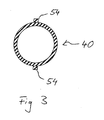
- longitudinal webs 54 in the area of the reduced outside diameter arranged, as can be seen from Fig. 3.
- two opposite longitudinal webs 54 are provided, which have an outer diameter define the particular the normal outer diameter of the control rod support element 40 in front of the tapered area 48.
- the longitudinal webs 54 can also if necessary be designed as rails.
- FIGS. 1 and 2 The principle shown in FIGS. 1 and 2 is preferably in a control rod drive 2 used for a boiling water reactor, such as in Fig. 4 is shown.
- the control rod drive 2 shown in FIG. 4 is thus concerned modified that the control rod support element shown schematically in FIGS. 1 to 3 40 instead of the hollow piston 24 shown in FIG. 4 with the constant outer diameter is used.
Abstract
Description
- Fig. 1
- ein ausschnittsweise und stark vereinfachte Darstellung eines Steuerstabantriebs im Bereich der Drosselbuchse, bei dem sich ein Steuerstabtragelement in einer Zwischenstellung zwischen einer unteren ausgefahrenen Grundstellung und einer oberen eingefahrenen Endstellung befindet,
- Fig. 2
- den ausschnittsweise dargestellten Steuerstabantrieb der Fig. 1 in der eingefahrenen oberen Endstellung und
- Fig. 3
- eine Querschnittsansicht des Steuerstabtragelements im Bereich des reduzierten Außendurchmessers mit Längsstegen,
- Fig. 4
- eine Darstellung eines Steuerstabantriebs in herkömmlicher Bauart.
- 2
- Steuerstabantrieb
- 4.
- Reaktordruckbehälter
- 6
- Stutzen
- 7
- Innenraum
- 8
- Antriebsgehäuse
- 9
- Antriebseinheit
- 10
- Motor
- 12
- Getriebe
- 14
- Antriebswelle
- 16
- Spindelantrieb
- 18
- Spindel
- 20
- Mutter
- 22
- Führungsrohr
- 24
- Hohlkolben
- 25
- Flansch
- 26
- Führungsrolle
- 27
- oberes Ende
- 28
- Kupplung
- 29
- Steuerstab
- 30
- Drosselbuchse
- 32
- Druckleitungsanschluss
- 34
- Federelement
- 40
- Steuerstabtragelement
- 42
- Strömungsweg
- 46
- Hohlraum
- 48
- Verjüngungsbereich
- 50
- Ringsteg
- 52
- Bypassöffnung
- 54
- Längsstege
Claims (12)
- Steuerstabantrieb (2) für einen Kernreaktor, insbesondere für einen Siedewasserreaktor, mit einem Antriebsgehäuse (8), in dem ein Steuerstabtragelement (40) zwischen einer Grundstellung und einer eingefahrenen Endstellung verfahrbar ist, das mit einem Teilabschnitt in einer Drosselbuchse (30) geführt ist und dessen unteres Ende (25) mit einer Antriebseinheit (9) zusammenwirkt,
dadurch gekennzeichnet, dass ein über die Drosselbuchse (30) hinweg führender Strömungsweg (42) für ein Druckfluid mit einem in Abhängigkeit der aktuellen Stellung des Steuerstabtragelements (40) variierenden freien Strömungsquerschnitt vorgesehen ist. - Steuerstabantrieb (2) nach Anspruch 1,
dadurch gekennzeichnet, dass der freie Strömungsquerschnitt von der Grundstellung zu der eingefahrenen Endstellung zunimmt. - Steuerstabantrieb (2) nach Anspruch 1 oder 2,
dadurch gekennzeichnet, dass das Steuerstabtragelement (40) einen sich verändernden Außendurchmesser aufweist. - Steuerstabantrieb (2) nach Anspruch 3,
dadurch gekennzeichnet, dass das Steuerstabtragelement (40) in einem unteren, der Antriebseinheit (9) zugewandten Bereich, einen reduzierten Außendurchmesser aufweist. - Steuerstabantrieb (2) nach Anspruch 3 oder 4,
dadurch gekennzeichnet, dass sich das Steuerstabtragelement (40) in einem Verjüngungsbereich (48) stetig auf den reduzierten Außendurchmesser verjüngt. - Steuerstabantrieb (2) nach Anspruch 4 oder 5,
dadurch gekennzeichnet, dass das Steuerstabtragelement (40) nur über einen Teil seiner Länge den reduzierten Durchmesser gleichbleibend aufweist. - Steuerstabantrieb (2) nach einem der vorhergehenden Ansprüche,
dadurch gekennzeichnet, dass das Steuerstabtragelement (40) als Hohlkolben ausgeführt ist, der in seiner Wand zumindest eine Bypassöffnung (52) aufweist. - Steuerstabantrieb (2) nach Anspruch 7 und Anspruch 4,
dadurch gekennzeichnet, dass die Bypassöffnung (52) im Bereich vor oder im Bereich der Verjüngung (48) des Steuerstabtragelements (40) auf den reduzierten Außendurchmesser angeordnet ist. - Steuerstabantrieb (2) nach einem der Ansprüche 4 bis 6 oder 8,
dadurch gekennzeichnet, dass das Steuerstabtragelement (40) im Bereich mit dem reduzierten Außendurchmesser einen Außensteg (50) aufweist, der sich innerhalb der Drosselbuchse (30) befindet, wenn das Steuerstabtragelement (40) in der eingefahrenen Endstellung positioniert ist. - Steuerstabantrieb (2) nach Anspruch 9,
dadurch gekennzeichnet, dass der Außensteg als umlaufender Ringsteg (50) ausgebildet ist, dessen Außendurchmesser in etwa dem Innendurchmesser der Drosselbuchse (30) entspricht. - Steuerstabantrieb nach einem der Ansprüche 4 bis 10,
dadurch gekennzeichnet, dass im Bereich des reduzierten Außendurchmessers Längsstege (54) angeordnet sind. - Verfahren zum Einfahren eines Steuerstabs (29) in einen Reaktorkern eines Kernreaktors, insbesondere zur Schnellabschaltung des Kernreaktors, bei dem ein Steuerstabtragelement (40), das den Steuerstab (29) trägt und in einem Teilbereich in einer Drosselbuchse (30) geführt ist, hydraulisch über ein Druckfluid verfahren wird,
dadurch gekennzeichnet, dass sich ein über der Drosselbuchse (30) ausbildender Strömungswiderstand für das Druckfluid verändert.
Applications Claiming Priority (2)
| Application Number | Priority Date | Filing Date | Title |
|---|---|---|---|
| DE10161219 | 2001-12-13 | ||
| DE10161219A DE10161219C1 (de) | 2001-12-13 | 2001-12-13 | Steuerstabantrieb für einen Kernreaktor und Verfahren zum Einfahren eines Steuerstabs in einen Reaktorkern eines Kernreaktors |
Publications (2)
| Publication Number | Publication Date |
|---|---|
| EP1320106A1 true EP1320106A1 (de) | 2003-06-18 |
| EP1320106B1 EP1320106B1 (de) | 2013-02-13 |
Family
ID=7709055
Family Applications (1)
| Application Number | Title | Priority Date | Filing Date |
|---|---|---|---|
| EP02027449A Expired - Lifetime EP1320106B1 (de) | 2001-12-13 | 2002-12-10 | Steuerstabantrieb für einen Kernreaktor und Verfahren zum Einfahren eines Steuerestabs in einen Reaktorkern eines Kernreaktors |
Country Status (5)
| Country | Link |
|---|---|
| US (1) | US7197103B2 (de) |
| EP (1) | EP1320106B1 (de) |
| JP (1) | JP4210108B2 (de) |
| DE (1) | DE10161219C1 (de) |
| TW (1) | TW574713B (de) |
Families Citing this family (7)
| Publication number | Priority date | Publication date | Assignee | Title |
|---|---|---|---|---|
| US9336910B2 (en) * | 2010-10-07 | 2016-05-10 | Bwxt Nuclear Energy, Inc. | Control rod/control rod drive mechanism couplings |
| US8953732B2 (en) * | 2010-12-09 | 2015-02-10 | Westinghouse Electric Company Llc | Nuclear reactor internal hydraulic control rod drive mechanism assembly |
| DE102011008202B3 (de) * | 2011-01-11 | 2012-06-14 | Areva Np Gmbh | Sicherungsvorrichtung für einen Steuerstab in einer kerntechnischen Anlage |
| KR101540181B1 (ko) * | 2014-05-19 | 2015-07-29 | 한국원자력연구원 | 연구용 원자로 하부설치 이차정지구동장치 |
| KR101669494B1 (ko) * | 2015-07-09 | 2016-10-26 | 한국원자력연구원 | 원자로의 제어봉 연결장치 |
| CN105973319A (zh) * | 2016-07-15 | 2016-09-28 | 中国核动力研究设计院 | 一种控制棒驱动机构排污系统水力特性计算方法 |
| CN107403648B (zh) * | 2017-07-25 | 2019-06-14 | 中国原子能科学研究院 | 一种用于非能动组件内部节流的装置 |
Citations (2)
| Publication number | Priority date | Publication date | Assignee | Title |
|---|---|---|---|---|
| DE1230140B (de) | 1960-06-15 | 1966-12-08 | Licentia Gmbh | Absorberstabantrieb fuer Kernreaktoren |
| DE3342838A1 (de) * | 1982-12-03 | 1984-06-07 | Heinz Dipl.-Ing. 6360 Friedberg Acher | Absorberstabantrieb fuer kernreaktoren |
Family Cites Families (9)
| Publication number | Priority date | Publication date | Assignee | Title |
|---|---|---|---|---|
| GB987880A (en) | 1960-06-15 | 1965-03-31 | Licentia Gmbh | A control rod drive for nuclear reactors |
| DE1614098A1 (de) * | 1967-11-24 | 1970-10-29 | Licentia Gmbh | Hydraulischer Antrieb zur Notabschaltung von Kernreaktoren |
| SE334686B (de) * | 1970-06-18 | 1971-05-03 | Asea Atom Ab | |
| US3752736A (en) * | 1970-09-30 | 1973-08-14 | Licentia Gmbh | Control rod arrangement particularly for boiling water reactors |
| US5276719A (en) * | 1991-08-14 | 1994-01-04 | Siemens Aktiengesellschaft | Hydraulic control rod drive for a nuclear reactor |
| US5581587A (en) * | 1993-05-10 | 1996-12-03 | Kabushiki Kaisha Toshiba | Control rod driving apparatus |
| DE4441751C1 (de) | 1994-11-23 | 1996-04-25 | Siemens Ag | Schnellabschaltsystem und Verfahren zur Schnellabschaltung eines Kernreaktors |
| US5661771A (en) | 1995-12-04 | 1997-08-26 | General Electric Company | Inner filter for a control rod drive |
| DE19827443A1 (de) | 1998-06-19 | 1999-12-30 | Siemens Ag | Verfahren zum Anfahren und zur Überwachung sowie Einrichtung zur Steuerung eines Siedewasser-Kernreaktors |
-
2001
- 2001-12-13 DE DE10161219A patent/DE10161219C1/de not_active Expired - Fee Related
-
2002
- 2002-12-10 EP EP02027449A patent/EP1320106B1/de not_active Expired - Lifetime
- 2002-12-11 TW TW91135868A patent/TW574713B/zh not_active IP Right Cessation
- 2002-12-12 JP JP2002361214A patent/JP4210108B2/ja not_active Expired - Fee Related
- 2002-12-13 US US10/319,345 patent/US7197103B2/en not_active Expired - Fee Related
Patent Citations (2)
| Publication number | Priority date | Publication date | Assignee | Title |
|---|---|---|---|---|
| DE1230140B (de) | 1960-06-15 | 1966-12-08 | Licentia Gmbh | Absorberstabantrieb fuer Kernreaktoren |
| DE3342838A1 (de) * | 1982-12-03 | 1984-06-07 | Heinz Dipl.-Ing. 6360 Friedberg Acher | Absorberstabantrieb fuer kernreaktoren |
Also Published As
| Publication number | Publication date |
|---|---|
| DE10161219C1 (de) | 2003-08-28 |
| JP4210108B2 (ja) | 2009-01-14 |
| US20070030941A1 (en) | 2007-02-08 |
| TW200301489A (en) | 2003-07-01 |
| US7197103B2 (en) | 2007-03-27 |
| EP1320106B1 (de) | 2013-02-13 |
| JP2003194981A (ja) | 2003-07-09 |
| TW574713B (en) | 2004-02-01 |
Similar Documents
| Publication | Publication Date | Title |
|---|---|---|
| DE60006002T2 (de) | Füllkopf mit durch eine einzige vorrichtung regelbarem durchfluss | |
| DE2646411A1 (de) | Rueckschlag-hubventil mit stossdaempfer | |
| DE602005006386T2 (de) | Mehrstufiger Teleskopausleger. | |
| EP1320106B1 (de) | Steuerstabantrieb für einen Kernreaktor und Verfahren zum Einfahren eines Steuerestabs in einen Reaktorkern eines Kernreaktors | |
| EP1106841A2 (de) | Linearverstellantrieb | |
| DE102004030045B3 (de) | Ventilanordnung in einem Hydraulikkreis, Verwendung derselben und Anordnung zum Steuern eines hydraulischen Fahrzeugantriebs | |
| DE1184865B (de) | Vorrichtung zur Erzeugung geradliniger gesteuerter Bewegungen | |
| DE2856057A1 (de) | Stossdaempfer fuer kernreaktorregelstaebe | |
| DE3711695A1 (de) | Verteilerkappe fuer eine einrichtung zur extrakorporalen behandlung von blut oder blutbestandteilen | |
| DE19711451C2 (de) | Absturzsicherung und Haltevorrichtung für eine Hubeinrichtung | |
| DE2914438A1 (de) | Einrichtung zur automatischen abschaltung der beschaedigten abzweigungen von pneumatik- und hydrauliksystemen | |
| DE3911426C2 (de) | Druckventil | |
| DE3010761A1 (de) | Zentrierzapfen zur zentrierung eines werkzeuges in einer bohrung eines werkstueckes | |
| EP0634248B1 (de) | Werkzeugmaschine, insbesondere Langbett-Werkzeugmaschine | |
| DE3101060C2 (de) | Verfahren und Vorrichtungen zur Steuerung eines Bohrgestänges | |
| DE2726759C3 (de) | Einrichtung zum Greifen und Anheben vertikal angeordneter, länglicher Bauelemente aus der aktiven Zone eines Kernreaktors | |
| EP3440340B1 (de) | Ringgatter für eine hydraulische maschine und verfahren zum schliessen | |
| DE3023704C2 (de) | Umlaufender Getränkefüller mit höhenbeweglichen Füllorganen | |
| DE2847951C2 (de) | Hydraulisch betätigter Hohlspannzylinder für Spanneinrichtungen an einer rotierenden Spindel, insbesondere Drehmaschinenspindel | |
| DE2856246C2 (de) | Absorberstab für einen Kugelhaufenreaktor | |
| DE3033591C2 (de) | Puffereinrichtung zum Bremsen eines in einem Kernreaktor vertikal angeordneten Linear-Bewegungsantriebs | |
| DE1162006B (de) | Vorrichtung zur Schnellabschaltung von Atomkernreaktoren | |
| EP0276361B1 (de) | Anlage mit einem nuklearen Reaktor, insbesondere Heizreaktor | |
| DE60216903T2 (de) | Kraftstoffeinspritzventil und verfahren zum einspritzen von kraftstoff | |
| DE1116487B (de) | Absperrventil mit stromlinienfoermigem Ventil-Verschlussstueck |
Legal Events
| Date | Code | Title | Description |
|---|---|---|---|
| PUAI | Public reference made under article 153(3) epc to a published international application that has entered the european phase |
Free format text: ORIGINAL CODE: 0009012 |
|
| AK | Designated contracting states |
Designated state(s): AT BE BG CH CY CZ DE DK EE ES FI FR GB GR IE IT LI LU MC NL PT SE SI SK TR |
|
| AX | Request for extension of the european patent |
Extension state: AL LT LV MK RO SI |
|
| 17P | Request for examination filed |
Effective date: 20031204 |
|
| AKX | Designation fees paid |
Designated state(s): CH DE DK ES FI LI SE |
|
| 17Q | First examination report despatched |
Effective date: 20040906 |
|
| RAP1 | Party data changed (applicant data changed or rights of an application transferred) |
Owner name: AREVA NP GMBH |
|
| RAP1 | Party data changed (applicant data changed or rights of an application transferred) |
Owner name: AREVA NP GMBH |
|
| GRAP | Despatch of communication of intention to grant a patent |
Free format text: ORIGINAL CODE: EPIDOSNIGR1 |
|
| GRAJ | Information related to disapproval of communication of intention to grant by the applicant or resumption of examination proceedings by the epo deleted |
Free format text: ORIGINAL CODE: EPIDOSDIGR1 |
|
| GRAP | Despatch of communication of intention to grant a patent |
Free format text: ORIGINAL CODE: EPIDOSNIGR1 |
|
| GRAS | Grant fee paid |
Free format text: ORIGINAL CODE: EPIDOSNIGR3 |
|
| GRAA | (expected) grant |
Free format text: ORIGINAL CODE: 0009210 |
|
| AK | Designated contracting states |
Kind code of ref document: B1 Designated state(s): CH DE DK ES FI LI SE |
|
| REG | Reference to a national code |
Ref country code: DE Ref legal event code: R096 Ref document number: 50215703 Country of ref document: DE Effective date: 20130411 |
|
| PG25 | Lapsed in a contracting state [announced via postgrant information from national office to epo] |
Ref country code: SE Free format text: LAPSE BECAUSE OF FAILURE TO SUBMIT A TRANSLATION OF THE DESCRIPTION OR TO PAY THE FEE WITHIN THE PRESCRIBED TIME-LIMIT Effective date: 20130213 Ref country code: ES Free format text: LAPSE BECAUSE OF FAILURE TO SUBMIT A TRANSLATION OF THE DESCRIPTION OR TO PAY THE FEE WITHIN THE PRESCRIBED TIME-LIMIT Effective date: 20130524 |
|
| PG25 | Lapsed in a contracting state [announced via postgrant information from national office to epo] |
Ref country code: FI Free format text: LAPSE BECAUSE OF FAILURE TO SUBMIT A TRANSLATION OF THE DESCRIPTION OR TO PAY THE FEE WITHIN THE PRESCRIBED TIME-LIMIT Effective date: 20130213 |
|
| PG25 | Lapsed in a contracting state [announced via postgrant information from national office to epo] |
Ref country code: DK Free format text: LAPSE BECAUSE OF FAILURE TO SUBMIT A TRANSLATION OF THE DESCRIPTION OR TO PAY THE FEE WITHIN THE PRESCRIBED TIME-LIMIT Effective date: 20130213 |
|
| PLBE | No opposition filed within time limit |
Free format text: ORIGINAL CODE: 0009261 |
|
| STAA | Information on the status of an ep patent application or granted ep patent |
Free format text: STATUS: NO OPPOSITION FILED WITHIN TIME LIMIT |
|
| 26N | No opposition filed |
Effective date: 20131114 |
|
| REG | Reference to a national code |
Ref country code: DE Ref legal event code: R097 Ref document number: 50215703 Country of ref document: DE Effective date: 20131114 |
|
| REG | Reference to a national code |
Ref country code: DE Ref legal event code: R119 Ref document number: 50215703 Country of ref document: DE |
|
| REG | Reference to a national code |
Ref country code: CH Ref legal event code: PL |
|
| REG | Reference to a national code |
Ref country code: DE Ref legal event code: R119 Ref document number: 50215703 Country of ref document: DE Effective date: 20140701 |
|
| PG25 | Lapsed in a contracting state [announced via postgrant information from national office to epo] |
Ref country code: DE Free format text: LAPSE BECAUSE OF NON-PAYMENT OF DUE FEES Effective date: 20140701 Ref country code: CH Free format text: LAPSE BECAUSE OF NON-PAYMENT OF DUE FEES Effective date: 20131231 Ref country code: LI Free format text: LAPSE BECAUSE OF NON-PAYMENT OF DUE FEES Effective date: 20131231 |