EP1319589B1 - Mehrfachschraubeinrichtung zum Befestigen eines Kfz-Rades an einer Radnabe oder dergleichen - Google Patents
Mehrfachschraubeinrichtung zum Befestigen eines Kfz-Rades an einer Radnabe oder dergleichen Download PDFInfo
- Publication number
- EP1319589B1 EP1319589B1 EP02025166A EP02025166A EP1319589B1 EP 1319589 B1 EP1319589 B1 EP 1319589B1 EP 02025166 A EP02025166 A EP 02025166A EP 02025166 A EP02025166 A EP 02025166A EP 1319589 B1 EP1319589 B1 EP 1319589B1
- Authority
- EP
- European Patent Office
- Prior art keywords
- base plate
- wheel
- axle
- vehicle wheel
- screwing
- Prior art date
- Legal status (The legal status is an assumption and is not a legal conclusion. Google has not performed a legal analysis and makes no representation as to the accuracy of the status listed.)
- Expired - Lifetime
Links
- 239000012528 membrane Substances 0.000 claims description 4
- 238000006073 displacement reaction Methods 0.000 claims description 2
- 230000007246 mechanism Effects 0.000 description 2
Images




Classifications
-
- B—PERFORMING OPERATIONS; TRANSPORTING
- B23—MACHINE TOOLS; METAL-WORKING NOT OTHERWISE PROVIDED FOR
- B23P—METAL-WORKING NOT OTHERWISE PROVIDED FOR; COMBINED OPERATIONS; UNIVERSAL MACHINE TOOLS
- B23P19/00—Machines for simply fitting together or separating metal parts or objects, or metal and non-metal parts, whether or not involving some deformation; Tools or devices therefor so far as not provided for in other classes
- B23P19/04—Machines for simply fitting together or separating metal parts or objects, or metal and non-metal parts, whether or not involving some deformation; Tools or devices therefor so far as not provided for in other classes for assembling or disassembling parts
- B23P19/06—Screw or nut setting or loosening machines
- B23P19/069—Multi-spindle machines
-
- B—PERFORMING OPERATIONS; TRANSPORTING
- B62—LAND VEHICLES FOR TRAVELLING OTHERWISE THAN ON RAILS
- B62D—MOTOR VEHICLES; TRAILERS
- B62D65/00—Designing, manufacturing, e.g. assembling, facilitating disassembly, or structurally modifying motor vehicles or trailers, not otherwise provided for
-
- B—PERFORMING OPERATIONS; TRANSPORTING
- B62—LAND VEHICLES FOR TRAVELLING OTHERWISE THAN ON RAILS
- B62D—MOTOR VEHICLES; TRAILERS
- B62D65/00—Designing, manufacturing, e.g. assembling, facilitating disassembly, or structurally modifying motor vehicles or trailers, not otherwise provided for
- B62D65/02—Joining sub-units or components to, or positioning sub-units or components with respect to, body shell or other sub-units or components
- B62D65/12—Joining sub-units or components to, or positioning sub-units or components with respect to, body shell or other sub-units or components the sub-units or components being suspensions, brakes or wheel units
Definitions
- the invention relates to a Mehrfachschraub adopted for attaching a vehicle wheel to a wheel hub or the like, in particular in the course of an assembly line for the chassis assembly of motor vehicles, wherein a plurality of angle screwdriver between a base plate and a top plate are arranged, the angled, provided with sockets inserts ends through holes extend the base plate, wherein the base plate has a holding device for the motor vehicle wheel.
- the Mehrfachschraub In known embodiments, the Mehrfachschraub worn is designed in each case for a given pitch circle diameter of the vehicle wheel. If vehicle wheels are to be mounted with a different pitch circle diameter, the multiple screw device must be replaced as a whole. Accordingly, a corresponding number of Mehrfachschraub discomforten must be kept available.
- the object of the invention is to improve a Mehrfachschraub worn of the type described above so that so that vehicle wheels can be mounted with different pitch circle diameters.
- each angle screws is mounted on a relative to the wheel axis radially adjustable guide carriage and that the holes of the base plate have a radial displacement of the angle screwdriver permitting dimensions.
- the actuator receiving ends of the angle screwdriver are usually arranged in two planes between the base plate and the top plate and extend in substantially the same directions.
- each guide carriage can be assigned at least one actuating drive fastened to the base plate or to the top plate.
- the actuators consist of Kurzhubzylindern that work against a prestressed membrane.
- each guide carriage to limit its adjustment between two short stroke cylinders actuators is arranged such that its end faces abut the membranes of Kurzhubzylinder, the one Kurzhubzylinder in the extended position and the other Kurzhubzylinder in the retracted position located. The adjustment is then carried out by pressing one or the other Kurzhubzylinders.
- the holding device for the vehicle wheel should consist of pivotally mounted on the base plate and provided with an associated drive Radgreiferarmen.
- a centering pin can be arranged on the base plate.
- the Mehrfachschraub worn in the drawing is used for mounting and attaching a motor vehicle wheel, not shown, to a wheel hub.
- the Mehrschraub worn is arranged with several similar in the course of an assembly line for the chassis assembly of motor vehicles. It is moved by means of a robot, not shown.
- the base plate 1 has several angeodnete on a pitch circle around the centering mandrel 7 holes 8, extending through the angled ends 9 of angle wrenches 10.
- the diameter of the holes 8 is greater than the diameter of the angled ends 9.
- the holes 8 may also be formed as longitudinal holes to allow a linear movement of the ends 9 in the radial direction.
- fastening screws 12 are already used, with which the vehicle wheel is bolted to the wheel hub, not shown.
- the angle wrenches 10 are arranged one above the other between the base plate 1 and the top plate 2 in two planes. In the base plate 1 adjacent level three angle wrenches 10 are arranged in the head plate 2 adjacent plane two angle screwdriver 10 are arranged. All angle wrenches 10 extend substantially in the same direction (see Figures 1 and 2).
- Each angle wrench 10 is mounted on a guide carriage 13 which is adjustable in the radial direction in relation to the wheel axle 16 defined by the centering pin 7 and the hole 8 associated with the respective angle screws 10 in the base plate 1.
- Fig. 5 it follows that the three arranged in the base plate 1 adjacent plane angle wrenches 10 guide carriages 13 are assigned, which are guided on the underside of the base plate 1. From Fig. 5 it also removes that the guide carriage 13 are guided for the two in the head plate 2 adjacent plane arranged angle wrench 10 at the top of the top plate 1.
- the guide carriages 13 are each guided in guide rails 14, which are fastened to the underside of the base plate 1 or to the upper side of the top plate 2.
- Each guide carriage 13 is arranged between two fixed to the base plate 1 and on the top plate 2 actuators 15.
- the actuators 15 consist of Kurzhubzylindern against a preloaded diaphragm work.
- the arrangement is such that each guide carriage 13 is arranged to limit its adjustment between the two associated actuators 15 such that its end faces abut the diaphragm of Kurzhubzylinder, the one Kurzhubzylinder is in the extended position and the other Kurzhubzylinder in the retracted position ,
- the actuator of the guide carriage in question is moved into one or the other position, and accordingly the angled ends 9 with the socket wrench inserts 11 of the angle screwdriver 10 in their associated holes 8 of the base plate 1 radially with respect to the through Centering pin 7 defined axle 16 are adjusted. This makes it easy to adapt the Mehrfachschraub worn to different pitch circle diameter of the vehicle wheel possible.
- the illustrated multiple screw device works as follows:
- An unillustrated robot brings the Mehrfachschraub worn in a position to take over the vehicle wheel, not shown. Either the fastening screws of the vehicle wheel are already inserted into the associated holes of the rim or they are inserted into the socket wrench inserts 11.
- the vehicle wheel is in any case set with a different device or another robot on the Mehrfachschraub observed that the socket wrench inserts 11 are aligned with the holes for the mounting screws 12.
- the vehicle wheel is held by operating the drive unit 5 of the Radgreiferarmen. Then we move the Mehrfachschraub worn together with the recorded vehicle wheel to the wheel hub and the vehicle wheel is bolted to the hub.
Landscapes
- Engineering & Computer Science (AREA)
- Mechanical Engineering (AREA)
- Manufacturing & Machinery (AREA)
- Chemical & Material Sciences (AREA)
- Combustion & Propulsion (AREA)
- Transportation (AREA)
- Automatic Assembly (AREA)
- Automobile Manufacture Line, Endless Track Vehicle, Trailer (AREA)
- Turbine Rotor Nozzle Sealing (AREA)
- Tires In General (AREA)
Description
- Die Erfindung betrifft eine Mehrfachschraubeinrichtung zum Befestigen eines Kfz-Rades an einer Radnabe oder dergleichen, insbesondere im Zuge einer Montagelinie für die Fahrwerksmontage von Kraftfahrzeugen, wobei mehrere Winkelschrauber zwischen einer Grundplatte und einer Kopfplatte angeordnet sind, deren abgewinkelte, mit Steckschlüsseleinsätzen versehene Enden sich durch Löcher der Grundplatte erstrecken, wobei die Grundplatte eine Halteeinrichtung für das Kfz-Rad aufweist.
- Die
US 6196089 A zeigt eine gattungsgemäße Mehrfachschraubeinrichtung. - Andere Mehrfachschraubeinrichtungen sind aus der
EP 0 640 521 B1 und aus der Praxis bekannt. In der Praxis werden an sich bekannte Winkelschrauber eingesetzt (DE 198 43 151 C2 ,DE 39 22 049 A1 ,DE 39 19 648 C2 ). - Im Zuge der Montagelinie wird ein zu montierendes Kfz-Rad von der Halteeinrichtung der Grundplatte aufgenommen und ausgerichtet. Danach werden fünf Befestigungsschrauben in zugeordnete Bohrungen des Kfz-Rades eingelegt. Anschließend wird das Kfz-Rad an die Radnabe herangeführt und dort passgerecht positioniert, sodass die Winkelschrauber die Befestigungsschrauben in die zugeordneten Gewindebohrungen eindrehen können.
- Bei bekannten Ausführungen ist die Mehrfachschraubeinrichtung jeweils für einen bestimmten Lochkreisdurchmesser des Kfz-Rades ausgelegt. Sollen Kfz-Räder mit einem anderen Lochkreisdurchmesser montiert werden, muss die Mehrfachschraubeinrichtung insgesamt ausgetauscht werden. Dementsprechend muss eine entsprechende Anzahl von Mehrfachschraubeinrichtungen zur Verfügung gehalten werden.
- Aufgabe der Erfindung ist es, eine Mehrfachschraubeinrichtung der eingangs beschriebenen Art so zu verbessern, dass damit Kfz-Räder mit unterschiedlichen Lochkreisdurchmessern montiert werden können.
- Diese Aufgabe wird dadurch gelöst, dass jeder Winkelschrauben auf einem in Bezug auf die Radachse radial verstellbaren Führungsschlitten befestigt ist und dass die Löcher der Grundplatte eine radiale Verschiebung der Winkelschrauber zulassende Abmessungen besitzen. Durch Verstellen der Führungsschlitten in radiale Richtung werden auch die sich durch die Löcher der Grundplatte erstreckende Enden der Winkelschrauber in radialer Richtung verstellt und können damit an unterschiedliche Lochkreisdurchmesser verschiedener Kfz-Räder angepasst werden.
- Aus Platzgründen sind die die Antriebe aufnehmenden Enden der Winkelschrauber in der Regel in zwei Ebenen zwischen der Grundplatte und der Kopfplatte angeordnet und erstrecken sich im Wesentlichen in gleiche Richtungen. Für derartige Fälle ist es zweckmäßig, wenn wenigstens einige Führungsschlitten an der Grundplatte und die anderen Führungsschlitten an der Kopfplatte geführt sind.
- Im Übrigen kann jedem Führungsschlitten wenigstens ein an der Grundplatte bzw. an der Kopfplatte befestigter Stelltrieb zugenordnet sein. Vorzugsweise bestehen die Stelltriebe aus Kurzhubzylindern, die gegen eine vorgespannte Membran arbeiten.
- In den meisten Fällen reicht es aus, wenn die sich durch die Löcher der Grundplatte erstreckenden Enden der Winkelschrauber auf zwei unterschiedliche Lochkreisdurchmesser einstellbar sind, z.B. auf die Lochkreisdurchmesser von 15" - und 16" - Kfz-Räder. Dann ist eine Ausführung vorteilhaft, bei der jeder Führungsschlitten zur Begrenzung seines Verstellweges zwischen zwei aus Kurzhubzylindern bestehenden Stelltrieben derart angeordnet ist, dass seine Stirnseiten an den Membranen der Kurzhubzylinder anliegen, wobei der eine Kurzhubzylinder sich in ausgefahrener Stellung und der andere Kurzhubzylinder sich in eingefahrener Stellung befindet. Die Verstellung erfolgt dann durch Betätigen des einen oder des anderen Kurzhubzylinders.
- Damit das mit Befestigungsschrauben versehene Kfz-Rad unter Aufrechterhaltung der exakten Ausrichtung der Befestigungsschrauben relativ zu den Steckschlüsseleinsätzen zusammen mit der Mehrfachschraubeinrichtung an die Radnabe herangeführt werden kann, sollte die Halteeinrichtung für das Kfz-Rad aus an der Grundplatte schwenkbar gelagerten und einem zugeordneten Antrieb versehenen Radgreiferarmen bestehen. Zum Zentrieren des Kfz-Rades an der Radnabe kann auf der Grundplatte ein Zentrierdorn angeordnet sein.
- Im Folgenden wird ein in der Zeichnung dargestelltes Ausführungsbeispiel erläutert; es zeigen:
- Fig. 1
- in perspektivischer Darstellung eine Mehrfachschraubeinrichtung zum Befestigen eines Kfz-Rades an einer Radnabe o.dgl.,
- Fig. 2
- eine Draufsicht auf die Oberseite des Gegenstandes nach Fig. 1,
- Fig. 3
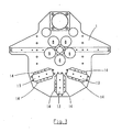
- eine Draufsicht auf die Unterseite der Grundplatte,
- Fig. 4
- eine Draufsicht auf die Oberseite der Kopfplatte,
- Fig. 5
- einen Vertikalschnitt durch den Gegenstand nach Fig. 1.
- Die in der Zeichnung dargestellte Mehrfachschraubeinrichtung dient zum Montieren und Befestigen eines nicht dargestellten Kfz-Rades an einer Radnabe. Die Mehrschraubeinrichtung ist mit mehreren gleichartigen im Zuge einer Montagelinie für die Fahrwerksmontage von Kraftfahrzeugen angeordnet. Sie wird mit Hilfe eines nicht dargestellten Roboters bewegt.
- Zu der Mehrfachschraubeinrichtung gehören eine Grundplatte 1 und eine im Abstand davon angeordnete Kopfplatte 2, die mit der Grundplatte 1 fest verbunden ist. Auf der Oberseite der Grundplatte 1 sind zwei einander gegenüberliegende Radgreiferarme 3 angeordnet, die in Führungen 4 mit Hilfe einer Antriebseinheit 5 und davon ausgehenden Hebelgetrieben 6 gegeneinander bzw. voneinander wegbewegbar sind. Mittig zwischen den beiden Radgreiferarmen 3 befindet sich ein Zentrierdorn 7, mit dem ein zwischen den beiden Radgreiferarmen 3 gehaltenes Kfz-Rad bei der Montage im Hinblick auf eine nicht dargestellten Radnabe zentriert wird.
- Die Grundplatte 1 weist mehrere auf einem Teilkreis um den Zentrierdorn 7 angeodnete Löcher 8 auf, durch die sich abgewinkelte Enden 9 von Winkelschraubern 10 erstrecken. Der Durchmesser der Löcher 8 ist größer als der Durchmesser der abgewinkelten Enden 9. Alternativ können die Löcher 8 auch als Längslöcher ausgebildet sein, um eine lineare Bewegung der Enden 9 in radialer Richtung zu ermöglichen. Die abgewinkelten Enden 9 tragen endseitig jeweils einen Steckschlüsseleinsatz 11. In einigen dieser Steckschlüsseleinsätze 11 sind bereits Befestigungsschrauben 12 eingesetzt, mit denen das Kfz-Rad mit der nicht dargestellten Radnabe verschraubt wird.
- Die Winkelschrauber 10 sind zwischen der Grundplatte 1 und der Kopfplatte 2 in zwei Ebenen übereinander angeordnet. In der der Grundplatte 1 benachbarten Ebene sind drei Winkelschrauber 10 angeordnet, in der der Kopfplatte 2 benachbarten Ebene sind zwei Winkelschrauber 10 angeordnet. Alle Winkelschrauber 10 erstrecken sich im Wesentlichen in die gleiche Richtung (siehe Figuren 1 und 2).
- Jeder Winkelschrauber 10 ist auf einem Führungsschlitten 13 befestigt, der in Bezug auf die durch den Zentrierdorn 7 definierte Radachse 16 und das den betreffenden Winkelschrauben 10 zugeordnete Loch 8 in der Grundplatte 1 in radialer Richtung verstellbar ist.
- Aus Fig. 5 entnimmt man, dass den drei in der der Grundplatte 1 benachbarten Ebene angeordneten Winkelschraubern 10 Führungsschlitten 13 zugeordnet sind, die an der Unterseite der Grundplatte 1 geführt sind. Aus Fig. 5 entnimmt man auch, dass die Führungsschlitten 13 für die beiden in der der Kopfplatte 2 benachbarten Ebene angeordneten Winkelschrauber 10 an der Oberseite der Kopfplatte 1 geführt sind. Die Führungsschlitten 13 werden jeweils in Führungsschienen 14 geführt, die an der Unterseite der Grundplatte 1 bzw. an der Oberseite der Kopfplatte 2 befestigt sind.
- Jeder Führungsschlitten 13 ist zwischen zwei an der Grundplatte 1 bzw. an der Kopfplatte 2 befestigten Stelltrieben 15 angeordnet. Bei der dargestellten Ausführung bestehen die Stelltriebe 15 aus Kurzhubzylindern, die gegen eine vorgespannte Membran arbeiten. Die Anordnung ist derart, dass jeder Führungschlitten 13 zur Begrenzung seines Verstellweges zwischen den beiden zugeordneten Stelltrieben 15 derart angeordnet ist, dass seine Stirnseiten an der Membran der Kurzhubzylinder anliegen, wobei der eine Kurzhubzylinder sich in ausgefahrener Stellung und der andere Kurzhubzylinder sich in eingefahrener Stellung befindet. Durch Betätigen des einen oder des anderen Stelltriebes wird der betreffende Führungsschlitten in die eine oder in die andere Position bewegt, wobei dementsprechend die abgewinkelten Enden 9 mit den Steckschlüsseleinsätzen 11 der Winkelschrauber 10 in ihren zugeordneten Löchern 8 der Grundplatte 1 radial in Bezug auf die durch den Zentrierdorn 7 definierte Radachse 16 verstellt werden. Dadurch ist auf einfache Weise eine Anpassung der Mehrfachschraubeinrichtung an unterschiedliche Lochkreisdurchmesser des Kfz-Rades möglich.
- Die dargestellte Mehrfachschraubeinrichtung arbeitet wie folgt:
- Ein nicht dargestellter Roboter bringt die Mehrfachschraubeinrichtung in eine Position zur Übernahme des nicht dargestellten Kfz-Rades. Entweder sind die Befestigungsschrauben des Kfz-Rades bereits in die zugeordneten Löcher der Felge eingesetzt oder sie sind in die Steckschlüsseleinsätze 11 eingesetzt. Das Kfz-Rad wird jedenfalls mit einer anderen Vorrichtung oder einem anderen Roboter so auf die Mehrfachschraubeinrichtung gesetzt, dass die Steckschlüsseleinsätze 11 mit den Löchern für die Befestigungsschrauben 12 fluchten. In dieser Position wird das Kfz-Rad nach Betätigen der Antriebseinheit 5 von den Radgreiferarmen gehalten. Anschließend wir die Mehrfachschraubeinrichtung zusammen mit dem aufgenommenen Kfz-Rad zur Radnabe bewegt und das Kfz-Rad wird mit der Radnabe verschraubt.
- Sollen Kfz-Räder mit einem anderen Lochkreisdurchmesser montiert werden, genügt es, die Stelltriebe 15 der Führungsschlitten 13 entsprechend zu betätigen.
-
- 1
- Grundplatte
- 2
- Kopfplatte
- 3
- Radgreiferarme
- 4
- Führungen
- 5
- Antriebseinheit
- 6
- Hebelgetriebe
- 7
- Zentrierdorn
- 8
- Löcher
- 9
- abgewinkelte Enden
- 10
- Winkelschrauber
- 11
- Steckschlüsseleinsatz
- 12
- Befestigungsschrauben
- 13
- Führungsschlitten
- 14
- Führungsschienen
- 15
- Stelltrieb
- 16
- Radachse
Claims (7)
- Mehrfachschraubeinrichtung zum Befestigen eines Kfz-Rades an einer Radnabe oder dergleichen, insbesondere im Zuge einer Montagelinie für die Fahrwerksmontage von Kraftfahrzeugen, wobei mehrere Winkelschrauber (10) zwischen einer Grundplatte (1) und einer Kopfplatte (2) angeordnet sind, deren abgewinkelte, mit Steckschlüsseleinsätzen (11) versehene Enden (9) sich durch Löcher (8) der Grundplatte (1) erstrecken, wobei die Grundplatte (1) eine Halteeinrichtung für das Kfz-Rad aufweist, dadurch gekennzeichnet, dass jeder Winkelschrauber (10) auf einem in Bezug auf die Radachse (16) radial verstellbaren Führungschlitten (13) befestigt ist, und dass die Löcher (8) der Grundplatte (1) eine radiale Verschiebung der Winkelschrauber (10) zulassende Abmessungen besitzen.
- Mehrfachschraubeinrichtung nach Anspruch 1, dadurch gekennzeichnet, dass wenigstens einige Führungsschlitten (13) an der Grundplatte (1) und die anderen Führungsschlitten (13) an der Kopfplatte (2) geführt sind.
- Mehrfachschraubeinrichtung nach Anspruch 1 oder 2, dadurch gekennzeichnet, dass jedem Führungsschlitten (13) wenigstens ein an der Grundplatte (1) bzw. an der Kopfplatte (2) befestigter Stelltrieb (15) zugeordnet ist.
- Mehrfachschraubeinrichtung nach einem der Ansprüche 1 bis 3, dadurch gekennzeichnet, dass die Stelltriebe (15) aus Kurzhubzylindern bestehen, die gegen eine vorgespant Membran arbeiten.
- Mehrfachschraubeinrichtung nach Anspruch 4, dadurch gekennzeichnet, dass jeder Führungsschlitten (13) zur Begrenzung seines Verstellweges zwischen zwei Stelltrieben (15) derart angeordnet ist, dass seine Stirnseiten an den Membranen der Kurzhubzylinder anliegen, wobei der eine Kurzhubzylinder sich in ausgefahrener Stellung und der andere Kurzhubzylinder sich in eingefahrener Stellung befindet.
- Mehrfachschraubeinrichtung nach Anspruch 1, dadurch gekennzeichnet, dass die Halteeinrichtung für das Kfz-Rad aus an der Grundplatte (1) schwenkbar oder verschiebbar gelagerten und mit einem zugeordneten Antrieb (5) versehenen Radgreiferarmen (3) besteht.
- Mehrfachschraubeinrichtung nach einem der Ansprüche 1 bis 6, dadurch gekennzeichnet, dass auf der Grundplatte (1) ein Zentrierdorn (7) zum Zentrieren des Kfz-Rades an der Radnabe oder dergleichen angeordnet ist.
Applications Claiming Priority (2)
| Application Number | Priority Date | Filing Date | Title |
|---|---|---|---|
| DE10161236 | 2001-12-13 | ||
| DE10161236A DE10161236C1 (de) | 2001-12-13 | 2001-12-13 | Mehrfachschraubeneinrichtung zum Befestigen eines Kfz-Rades an einer Radnabe oder dergleichen |
Publications (2)
| Publication Number | Publication Date |
|---|---|
| EP1319589A1 EP1319589A1 (de) | 2003-06-18 |
| EP1319589B1 true EP1319589B1 (de) | 2007-08-29 |
Family
ID=7709068
Family Applications (1)
| Application Number | Title | Priority Date | Filing Date |
|---|---|---|---|
| EP02025166A Expired - Lifetime EP1319589B1 (de) | 2001-12-13 | 2002-11-11 | Mehrfachschraubeinrichtung zum Befestigen eines Kfz-Rades an einer Radnabe oder dergleichen |
Country Status (4)
| Country | Link |
|---|---|
| EP (1) | EP1319589B1 (de) |
| AT (1) | ATE371572T1 (de) |
| DE (2) | DE10161236C1 (de) |
| ES (1) | ES2291410T3 (de) |
Families Citing this family (8)
| Publication number | Priority date | Publication date | Assignee | Title |
|---|---|---|---|---|
| DE102008007146B4 (de) * | 2008-01-31 | 2019-02-07 | Robert Bosch Gmbh | Montagewerkzeug |
| CN104999264A (zh) * | 2015-07-15 | 2015-10-28 | 苏州金牛精密机械有限公司 | 自动打螺丝机 |
| CN105197524B (zh) * | 2015-10-26 | 2017-12-26 | 天津新玛特科技发展有限公司 | 柔性焊装线台车定位销自动切换设备 |
| CN106181352B (zh) * | 2016-08-30 | 2018-03-16 | 博众精工科技股份有限公司 | 一种密封圈的组装装置 |
| CN107042404A (zh) * | 2017-05-25 | 2017-08-15 | 山西建筑工程有限公司 | 一种扣件维修装置 |
| CN111113317A (zh) * | 2020-01-13 | 2020-05-08 | 山东京普太阳能科技股份有限公司 | 一种太阳能搪瓷内胆法兰盘固定用组合气动扳手 |
| CN113146221B (zh) * | 2021-04-30 | 2024-10-15 | 深圳市合力士机电设备有限公司 | 马达胶螺丝自动化组装设备及其方法 |
| CN115971872B (zh) * | 2023-03-20 | 2023-05-23 | 招远市蚁龙矿山设备制造有限公司 | 一种矿用铲运机轮毂螺栓压紧锁紧装置 |
Family Cites Families (9)
| Publication number | Priority date | Publication date | Assignee | Title |
|---|---|---|---|---|
| US3491427A (en) * | 1967-05-01 | 1970-01-27 | Zimmerman D W Mfg | Apparatus for handling and assembling objects |
| JPS59145671A (ja) * | 1983-02-10 | 1984-08-21 | Nissan Motor Co Ltd | タイヤ自動取付装置におけるハンドの開閉駆動方法 |
| US5125298A (en) * | 1983-11-14 | 1992-06-30 | Smith Chalmers O | Automatic wheel assembly mounting system |
| SE8802566L (sv) * | 1988-07-08 | 1990-01-09 | Atlas Copco Tools Ab | Motordrivet verktyg och drivsystem foer detta |
| DE3919648C2 (de) * | 1989-06-16 | 1998-01-29 | Bosch Gmbh Robert | Winkelschrauber |
| JP3316086B2 (ja) * | 1993-07-02 | 2002-08-19 | マツダ株式会社 | 車輪の取付装置及び取付方法 |
| JP3042270B2 (ja) * | 1993-08-30 | 2000-05-15 | トヨタ自動車株式会社 | 車輪の組付け装置 |
| DE19843151C2 (de) * | 1998-09-21 | 2001-03-08 | Alfing Montagetechnik Gmbh | Bearbeitungsvorrichtung mit mindestens einem Bearbeitungswerkzeug |
| US6196089B1 (en) * | 1999-01-27 | 2001-03-06 | Hyundai Motor Company | Hub nut fastener for mounting wheel |
-
2001
- 2001-12-13 DE DE10161236A patent/DE10161236C1/de not_active Expired - Fee Related
-
2002
- 2002-11-11 DE DE50210803T patent/DE50210803D1/de not_active Expired - Lifetime
- 2002-11-11 EP EP02025166A patent/EP1319589B1/de not_active Expired - Lifetime
- 2002-11-11 ES ES02025166T patent/ES2291410T3/es not_active Expired - Lifetime
- 2002-11-11 AT AT02025166T patent/ATE371572T1/de not_active IP Right Cessation
Also Published As
| Publication number | Publication date |
|---|---|
| ATE371572T1 (de) | 2007-09-15 |
| EP1319589A1 (de) | 2003-06-18 |
| ES2291410T3 (es) | 2008-03-01 |
| DE10161236C1 (de) | 2003-06-18 |
| DE50210803D1 (de) | 2007-10-11 |
Similar Documents
| Publication | Publication Date | Title |
|---|---|---|
| DE10010709C1 (de) | Einstellvorrichtung für einen Cockpitquerträger | |
| DE102006025844B3 (de) | Handlingsystem für formverwandte Bauteile, insbesondere Karosseriebauteile für Kraftfahrzeuge | |
| DE4236670A1 (de) | Klemmspannvorrichtung | |
| DE102009037215A1 (de) | Verfahren zur Dichtungsapplikation an Bauteilen und Anlage zur Durchführung des Verfahrens | |
| WO2004050393A1 (de) | Spannvorrichtung für felgen, insbesondere zur reifenmontage | |
| DE102005049494B3 (de) | Handlingsystem für formverwandte Bauteile, insbesondere Karosseriebauteile für Kraftfahrzeuge | |
| DE102006035025A1 (de) | Federbeinpositionierungsvorrichtung | |
| DE10161236C1 (de) | Mehrfachschraubeneinrichtung zum Befestigen eines Kfz-Rades an einer Radnabe oder dergleichen | |
| EP1815939B1 (de) | Halterung für eine Spanneinheit mit über Führungsnuten und Nutensteine verschiebbaren Stellplatten und Konsole ; Spannvorrichtung mit einer solchen Halterung | |
| EP0737601B1 (de) | Vorrichtung zum rutschfreien Transport von Gegenständen auf Ladeflächen von Kraftfahrzeugen | |
| DE20319159U1 (de) | Bearbeitungstisch zum Halten von Werkstücken | |
| DE1966669B2 (de) | Vorrichtung zum Parallelverschieben eines plattenförmigen Bauteils, insbesondere eines Werkstückes. Ausscheidung aus: 1931840 | |
| DE4412085C2 (de) | Vorrichtung zum lösbaren Festsetzen von Wechselbehältern | |
| DE19802918A1 (de) | Vorrichtung zum Montieren von Scheiben an einer kfz-Karosserie | |
| DE4331976A1 (de) | Federbein | |
| DE19533573A1 (de) | Richtvorrichtung für Autokarosserien und Verfahren zum Richten der Karosserie | |
| DE102004044017A1 (de) | Kraftfahrzeugrahmenmodul eines modular aufgebauten Kraftfahrzeugrahmens | |
| DE2303102B2 (de) | Vorrichtung zum einstellen des sturzes und des nachlaufs fuer ein einzeln aufgehaengtes kraftfahrzeugvorderrad | |
| DE102009048186A1 (de) | Vorrichtung zur Montage eines Lenkerelements sowie Verfahren zur Montage eines Lenkerelements | |
| EP1901953B1 (de) | Klemmvorrichtung für eine lenksäule | |
| EP0236379A1 (de) | Vorrichtung zum wechseln von werkzeugen bei schleifoperationen. | |
| DE29703680U1 (de) | Vorrichtung zum Haltern und Führen von Energie- oder Steuer-Leitungen bei Robotern | |
| DE19920521C2 (de) | Ausrichtvorrichtung zum Einpassen eines Kraftfahrzeugschweinwerfers in einen Karosserieausschnitt | |
| DE19730966A1 (de) | Auflage-, Schweiß- und Montagevorrichtung für Großbaugruppen im Fahrzeugbau, insbesondere Schienenfahrzeugbau | |
| EP0847818B1 (de) | Transferpresse |
Legal Events
| Date | Code | Title | Description |
|---|---|---|---|
| PUAI | Public reference made under article 153(3) epc to a published international application that has entered the european phase |
Free format text: ORIGINAL CODE: 0009012 |
|
| AK | Designated contracting states |
Designated state(s): AT BE BG CH CY CZ DE DK EE ES FI FR GB GR IE IT LI LU MC NL PT SE SK TR |
|
| AX | Request for extension of the european patent |
Extension state: AL LT LV MK RO SI |
|
| 17P | Request for examination filed |
Effective date: 20031111 |
|
| AKX | Designation fees paid |
Designated state(s): AT BE BG CH CY CZ DE DK EE ES FI FR GB GR IE IT LI LU MC NL PT SE SK TR |
|
| RAP1 | Party data changed (applicant data changed or rights of an application transferred) |
Owner name: THYSSENKRUPP DRAUZ NOTHELFER GMBH |
|
| GRAP | Despatch of communication of intention to grant a patent |
Free format text: ORIGINAL CODE: EPIDOSNIGR1 |
|
| GRAS | Grant fee paid |
Free format text: ORIGINAL CODE: EPIDOSNIGR3 |
|
| GRAA | (expected) grant |
Free format text: ORIGINAL CODE: 0009210 |
|
| AK | Designated contracting states |
Kind code of ref document: B1 Designated state(s): AT BE BG CH CY CZ DE DK EE ES FI FR GB GR IE IT LI LU MC NL PT SE SK TR |
|
| REG | Reference to a national code |
Ref country code: GB Ref legal event code: FG4D Free format text: NOT ENGLISH |
|
| REG | Reference to a national code |
Ref country code: CH Ref legal event code: EP |
|
| REG | Reference to a national code |
Ref country code: IE Ref legal event code: FG4D Free format text: LANGUAGE OF EP DOCUMENT: GERMAN |
|
| REF | Corresponds to: |
Ref document number: 50210803 Country of ref document: DE Date of ref document: 20071011 Kind code of ref document: P |
|
| REG | Reference to a national code |
Ref country code: SE Ref legal event code: TRGR |
|
| PG25 | Lapsed in a contracting state [announced via postgrant information from national office to epo] |
Ref country code: NL Free format text: LAPSE BECAUSE OF FAILURE TO SUBMIT A TRANSLATION OF THE DESCRIPTION OR TO PAY THE FEE WITHIN THE PRESCRIBED TIME-LIMIT Effective date: 20070829 Ref country code: FI Free format text: LAPSE BECAUSE OF FAILURE TO SUBMIT A TRANSLATION OF THE DESCRIPTION OR TO PAY THE FEE WITHIN THE PRESCRIBED TIME-LIMIT Effective date: 20070829 |
|
| NLV1 | Nl: lapsed or annulled due to failure to fulfill the requirements of art. 29p and 29m of the patents act | ||
| GBT | Gb: translation of ep patent filed (gb section 77(6)(a)/1977) |
Effective date: 20080206 |
|
| REG | Reference to a national code |
Ref country code: ES Ref legal event code: FG2A Ref document number: 2291410 Country of ref document: ES Kind code of ref document: T3 |
|
| REG | Reference to a national code |
Ref country code: IE Ref legal event code: FD4D |
|
| EN | Fr: translation not filed | ||
| PG25 | Lapsed in a contracting state [announced via postgrant information from national office to epo] |
Ref country code: DK Free format text: LAPSE BECAUSE OF FAILURE TO SUBMIT A TRANSLATION OF THE DESCRIPTION OR TO PAY THE FEE WITHIN THE PRESCRIBED TIME-LIMIT Effective date: 20070829 Ref country code: GR Free format text: LAPSE BECAUSE OF FAILURE TO SUBMIT A TRANSLATION OF THE DESCRIPTION OR TO PAY THE FEE WITHIN THE PRESCRIBED TIME-LIMIT Effective date: 20071130 |
|
| PG25 | Lapsed in a contracting state [announced via postgrant information from national office to epo] |
Ref country code: PT Free format text: LAPSE BECAUSE OF FAILURE TO SUBMIT A TRANSLATION OF THE DESCRIPTION OR TO PAY THE FEE WITHIN THE PRESCRIBED TIME-LIMIT Effective date: 20080129 Ref country code: CZ Free format text: LAPSE BECAUSE OF FAILURE TO SUBMIT A TRANSLATION OF THE DESCRIPTION OR TO PAY THE FEE WITHIN THE PRESCRIBED TIME-LIMIT Effective date: 20070829 Ref country code: IE Free format text: LAPSE BECAUSE OF FAILURE TO SUBMIT A TRANSLATION OF THE DESCRIPTION OR TO PAY THE FEE WITHIN THE PRESCRIBED TIME-LIMIT Effective date: 20070829 Ref country code: SK Free format text: LAPSE BECAUSE OF FAILURE TO SUBMIT A TRANSLATION OF THE DESCRIPTION OR TO PAY THE FEE WITHIN THE PRESCRIBED TIME-LIMIT Effective date: 20070829 |
|
| BERE | Be: lapsed |
Owner name: THYSSENKRUPP DRAUZ NOTHELFER G.M.B.H. Effective date: 20071130 |
|
| ET | Fr: translation filed | ||
| REG | Reference to a national code |
Ref country code: FR Ref legal event code: EERR Free format text: CORRECTION DE BOPI 08/17 - BREVETS EUROPEENS DONT LA TRADUCTION N A PAS ETE REMISE A L INPI. IL Y A LIEU DE SUPPRIMER : LA MENTION DE LA NON-REMISE. LA REMISE DE LA TRADUCTION EST PUBLIEE DANS LE PRESENT BOPI. |
|
| PG25 | Lapsed in a contracting state [announced via postgrant information from national office to epo] |
Ref country code: MC Free format text: LAPSE BECAUSE OF NON-PAYMENT OF DUE FEES Effective date: 20071130 |
|
| PLBE | No opposition filed within time limit |
Free format text: ORIGINAL CODE: 0009261 |
|
| STAA | Information on the status of an ep patent application or granted ep patent |
Free format text: STATUS: NO OPPOSITION FILED WITHIN TIME LIMIT |
|
| PG25 | Lapsed in a contracting state [announced via postgrant information from national office to epo] |
Ref country code: LI Free format text: LAPSE BECAUSE OF NON-PAYMENT OF DUE FEES Effective date: 20071130 Ref country code: CH Free format text: LAPSE BECAUSE OF NON-PAYMENT OF DUE FEES Effective date: 20071130 |
|
| REG | Reference to a national code |
Ref country code: CH Ref legal event code: PL |
|
| 26N | No opposition filed |
Effective date: 20080530 |
|
| PG25 | Lapsed in a contracting state [announced via postgrant information from national office to epo] |
Ref country code: BE Free format text: LAPSE BECAUSE OF NON-PAYMENT OF DUE FEES Effective date: 20071130 |
|
| PG25 | Lapsed in a contracting state [announced via postgrant information from national office to epo] |
Ref country code: EE Free format text: LAPSE BECAUSE OF FAILURE TO SUBMIT A TRANSLATION OF THE DESCRIPTION OR TO PAY THE FEE WITHIN THE PRESCRIBED TIME-LIMIT Effective date: 20070829 |
|
| PG25 | Lapsed in a contracting state [announced via postgrant information from national office to epo] |
Ref country code: AT Free format text: LAPSE BECAUSE OF NON-PAYMENT OF DUE FEES Effective date: 20071111 |
|
| PG25 | Lapsed in a contracting state [announced via postgrant information from national office to epo] |
Ref country code: CY Free format text: LAPSE BECAUSE OF FAILURE TO SUBMIT A TRANSLATION OF THE DESCRIPTION OR TO PAY THE FEE WITHIN THE PRESCRIBED TIME-LIMIT Effective date: 20070829 |
|
| PG25 | Lapsed in a contracting state [announced via postgrant information from national office to epo] |
Ref country code: BG Free format text: LAPSE BECAUSE OF FAILURE TO SUBMIT A TRANSLATION OF THE DESCRIPTION OR TO PAY THE FEE WITHIN THE PRESCRIBED TIME-LIMIT Effective date: 20071129 Ref country code: LU Free format text: LAPSE BECAUSE OF NON-PAYMENT OF DUE FEES Effective date: 20071111 |
|
| PG25 | Lapsed in a contracting state [announced via postgrant information from national office to epo] |
Ref country code: TR Free format text: LAPSE BECAUSE OF FAILURE TO SUBMIT A TRANSLATION OF THE DESCRIPTION OR TO PAY THE FEE WITHIN THE PRESCRIBED TIME-LIMIT Effective date: 20070829 |
|
| PGFP | Annual fee paid to national office [announced via postgrant information from national office to epo] |
Ref country code: FR Payment date: 20101130 Year of fee payment: 9 |
|
| PGFP | Annual fee paid to national office [announced via postgrant information from national office to epo] |
Ref country code: DE Payment date: 20101119 Year of fee payment: 9 |
|
| PGFP | Annual fee paid to national office [announced via postgrant information from national office to epo] |
Ref country code: IT Payment date: 20101124 Year of fee payment: 9 Ref country code: SE Payment date: 20101112 Year of fee payment: 9 Ref country code: GB Payment date: 20101118 Year of fee payment: 9 |
|
| PGFP | Annual fee paid to national office [announced via postgrant information from national office to epo] |
Ref country code: ES Payment date: 20101124 Year of fee payment: 9 |
|
| REG | Reference to a national code |
Ref country code: SE Ref legal event code: EUG |
|
| GBPC | Gb: european patent ceased through non-payment of renewal fee |
Effective date: 20111111 |
|
| REG | Reference to a national code |
Ref country code: FR Ref legal event code: ST Effective date: 20120731 |
|
| PG25 | Lapsed in a contracting state [announced via postgrant information from national office to epo] |
Ref country code: IT Free format text: LAPSE BECAUSE OF NON-PAYMENT OF DUE FEES Effective date: 20111111 |
|
| REG | Reference to a national code |
Ref country code: DE Ref legal event code: R119 Ref document number: 50210803 Country of ref document: DE Effective date: 20120601 |
|
| PG25 | Lapsed in a contracting state [announced via postgrant information from national office to epo] |
Ref country code: GB Free format text: LAPSE BECAUSE OF NON-PAYMENT OF DUE FEES Effective date: 20111111 Ref country code: SE Free format text: LAPSE BECAUSE OF NON-PAYMENT OF DUE FEES Effective date: 20111112 |
|
| PG25 | Lapsed in a contracting state [announced via postgrant information from national office to epo] |
Ref country code: FR Free format text: LAPSE BECAUSE OF NON-PAYMENT OF DUE FEES Effective date: 20111130 |
|
| REG | Reference to a national code |
Ref country code: ES Ref legal event code: FD2A Effective date: 20130605 |
|
| PG25 | Lapsed in a contracting state [announced via postgrant information from national office to epo] |
Ref country code: DE Free format text: LAPSE BECAUSE OF NON-PAYMENT OF DUE FEES Effective date: 20120601 |
|
| PG25 | Lapsed in a contracting state [announced via postgrant information from national office to epo] |
Ref country code: ES Free format text: LAPSE BECAUSE OF NON-PAYMENT OF DUE FEES Effective date: 20111112 |