EP1319306B1 - Systeme de communication telephonique et procede applique a un cablage de reseau local - Google Patents
Systeme de communication telephonique et procede applique a un cablage de reseau local Download PDFInfo
- Publication number
- EP1319306B1 EP1319306B1 EP01928176A EP01928176A EP1319306B1 EP 1319306 B1 EP1319306 B1 EP 1319306B1 EP 01928176 A EP01928176 A EP 01928176A EP 01928176 A EP01928176 A EP 01928176A EP 1319306 B1 EP1319306 B1 EP 1319306B1
- Authority
- EP
- European Patent Office
- Prior art keywords
- transformers
- connector
- connection
- signals
- casing
- Prior art date
- Legal status (The legal status is an assumption and is not a legal conclusion. Google has not performed a legal analysis and makes no representation as to the accuracy of the status listed.)
- Expired - Lifetime
Links
Images


Classifications
-
- H—ELECTRICITY
- H04—ELECTRIC COMMUNICATION TECHNIQUE
- H04L—TRANSMISSION OF DIGITAL INFORMATION, e.g. TELEGRAPHIC COMMUNICATION
- H04L5/00—Arrangements affording multiple use of the transmission path
- H04L5/20—Arrangements affording multiple use of the transmission path using different combinations of lines, e.g. phantom working
-
- H—ELECTRICITY
- H04—ELECTRIC COMMUNICATION TECHNIQUE
- H04M—TELEPHONIC COMMUNICATION
- H04M11/00—Telephonic communication systems specially adapted for combination with other electrical systems
- H04M11/06—Simultaneous speech and data transmission, e.g. telegraphic transmission over the same conductors
- H04M11/062—Simultaneous speech and data transmission, e.g. telegraphic transmission over the same conductors using different frequency bands for speech and other data
-
- H—ELECTRICITY
- H04—ELECTRIC COMMUNICATION TECHNIQUE
- H04M—TELEPHONIC COMMUNICATION
- H04M11/00—Telephonic communication systems specially adapted for combination with other electrical systems
- H04M11/06—Simultaneous speech and data transmission, e.g. telegraphic transmission over the same conductors
- H04M11/066—Telephone sets adapted for data transmision
-
- H—ELECTRICITY
- H04—ELECTRIC COMMUNICATION TECHNIQUE
- H04B—TRANSMISSION
- H04B3/00—Line transmission systems
- H04B3/54—Systems for transmission via power distribution lines
- H04B3/542—Systems for transmission via power distribution lines the information being in digital form
-
- H—ELECTRICITY
- H04—ELECTRIC COMMUNICATION TECHNIQUE
- H04L—TRANSMISSION OF DIGITAL INFORMATION, e.g. TELEGRAPHIC COMMUNICATION
- H04L12/00—Data switching networks
- H04L12/66—Arrangements for connecting between networks having differing types of switching systems, e.g. gateways
-
- H—ELECTRICITY
- H04—ELECTRIC COMMUNICATION TECHNIQUE
- H04L—TRANSMISSION OF DIGITAL INFORMATION, e.g. TELEGRAPHIC COMMUNICATION
- H04L12/00—Data switching networks
- H04L12/64—Hybrid switching systems
- H04L12/6418—Hybrid transport
- H04L2012/6421—Medium of transmission, e.g. fibre, cable, radio, satellite
-
- H—ELECTRICITY
- H04—ELECTRIC COMMUNICATION TECHNIQUE
- H04L—TRANSMISSION OF DIGITAL INFORMATION, e.g. TELEGRAPHIC COMMUNICATION
- H04L12/00—Data switching networks
- H04L12/64—Hybrid switching systems
- H04L12/6418—Hybrid transport
- H04L2012/6424—Access arrangements
-
- H—ELECTRICITY
- H04—ELECTRIC COMMUNICATION TECHNIQUE
- H04L—TRANSMISSION OF DIGITAL INFORMATION, e.g. TELEGRAPHIC COMMUNICATION
- H04L12/00—Data switching networks
- H04L12/64—Hybrid switching systems
- H04L12/6418—Hybrid transport
- H04L2012/6432—Topology
- H04L2012/644—Star
-
- Y—GENERAL TAGGING OF NEW TECHNOLOGICAL DEVELOPMENTS; GENERAL TAGGING OF CROSS-SECTIONAL TECHNOLOGIES SPANNING OVER SEVERAL SECTIONS OF THE IPC; TECHNICAL SUBJECTS COVERED BY FORMER USPC CROSS-REFERENCE ART COLLECTIONS [XRACs] AND DIGESTS
- Y10—TECHNICAL SUBJECTS COVERED BY FORMER USPC
- Y10S—TECHNICAL SUBJECTS COVERED BY FORMER USPC CROSS-REFERENCE ART COLLECTIONS [XRACs] AND DIGESTS
- Y10S439/00—Electrical connectors
- Y10S439/95—Electrical connector adapted to transmit electricity to mating connector without physical contact, e.g. by induction, magnetism, or electrostatic field
Definitions
- the present invention relates to the field of common networks for data communication and telephony, and, more specifically, to the networking of telephone sets within a building over digitally oriented local area network wiring, simultaneously with the data transmission.
- Small office and business environments commonly employ a multiplicity of work cells, each equipped with a telephone set and a computer.
- Two separate networks are usually employed for communication among the cells and between them and the outside world - a telephone network, connecting between the telephone sets and outside telephone lines, and a so-called local area network (LAN), connecting the computers among themselves and to outside network lines.
- LAN local area network
- the term computer or personal computer will be understood to include a workstation or other data terminal equipment (DTE) or at least one digital device capable of inputting and outputting data, whereby each computer includes an interface for connection to a local area network (LAN), used for digital data transmission; any such device will also be referred to as a remote digital device.
- DTE data terminal equipment
- LAN local area network
- telephone set will be understood to include any device which can connect to a PSTN ( Public Switched Telephone Network), using telephony band signals, such as fax machine, automatic answering machine or dial-up modem; any such device will also be referred to as a remote- or local telephone device.
- PSTN Public Switched Telephone Network
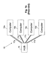
- FIG. 1a shows a telephony network 10 comprising a PABX (Private Automatic Branch Exchange) 11 , connected via lines 12a, 12b, 12c and 12d to telephone devices 13a, 13b, 13c and 13d respectively.
- the telephone are of the POTS (Plain Old Telephone Service) type, requiring each of the connecting lines 12 to consist of a single pair of wires.
- Fig. 1b shows a local area network (LAN) 15 for allowing communication between computers.
- LAN local area network
- Such a network comprises a hub (or switching hub) 16, connected via lines 17a, 17b, 17c and 17d to computers 18a, 18b, 18c and 18d respectively.
- Popular types of LANs are based on the IEEE802.3 Ethernet standard, using 10BaseT or 100BaseTX interfaces and employing, for each connecting line 17, two twisted pairs of wires - one pair for transmitting and one pair for receiving.
- VoIP Voice-Over-Internet-Protocol
- Another, opposite approach is to utilize an existing telephone infrastructure for simultaneously serving as both telephone and data networking. In this way, the task of establishing a new local area network in a home or other building is simplified, because there are no additional wires to install.
- FDM frequency division multiplexing
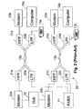
- FIG. 2 shows schematically a combined telephony/data network 20, providing in this case connections to two work cells by means of corresponding two cables 12a and 12b, each comprising a single twisted pair of wires.
- the lower part of the spectrum of cable 12a is isolated by Low Pass Filters (LPF) 22a and 22b, each connected to a respective end of the cable.
- LPF Low Pass Filters
- HPF High Pass Filters
- the telephony network uses the lower spectrum part by connecting the telephone 13a and the PABX 11 to the respective LPFs.
- telephone-line modems 23a and 23b are respectively connected to the HPFs 21a and 21b at both cable ends.
- Hub 16 connects to modem 23a, while, on the user side, modem 23b connects to computer 18a, thus offering connectivity between the computer and the hub.
- the spectrum of the other cable 12b is similarly split and cable 12b connects telephone set 13b to PABX 11 via LPFs 22c and 22d, while computer 18b connects to hub 16 via modem 23d, coupled to HPF 21d, and modem 23c, coupled to HPF 21c. Additional telephones 13 and computers 18 can be added in the same manner. This prior-art concept is disclosed in U.S.
- U.S. Patent 5,610,922 to Balatoni discloses a method and apparatus for transferring analog voice telephone signals and digital data service signals simultaneously from a telephone company location to a customer premises over a single twisted pair telephone line.
- the apparatus includes an easily installed voice plus digital data service remote terminal and voice plus digital data service central office terminal.
- the apparatus can provide a 3-to-1 pair gain by multiplexing signals representing the analog voice telephone signals and 4-wire digital data service signals.
- Network 20 typically requires two modems (such as 23a and 23b in Fig. 2 ) for each connected cell. Such modems are complex and expensive. In addition, the low communication quality of a typical telephone line, which was designed to carry low-frequency (telephony) signals only, limits both the data-rate and the distance of the data communication.
- US-A-3 975 594 describes a subscriber line circuit for telecommunication systems in which additional message signals, e.g., video signals, can be transmitted.
- the line circuit is constituted by two balanced line pairs which, if necessary, can have line amplifiers interposed therein.
- a remote supply circuit for the amplifiers, constructed in the form of a phantom circuit, is used, and this phantom circuit is used, as well, as the transmission circuit for the additional message signals.
- a subscriber set for the additional message signals is connected to the phantom circuit. A feed to the latter subscriber set, as well as two way communication take place over the phantom circuit.
- circuit for use with a bundle containing at least two pairs of conductors, the circuit comprising:
- Conventional data networks use a four-conductor circuit arrangement providing two communication channels between two units.
- a local area network based on Ethernet 10BaseT or 100BaseTX
- two pairs of conductors are employed between a hub and DTE such as a computer.
- POTS connection such as between exchange and telephone apparatus, is accomplished simultaneously over the same four conductors used for the two communication channels without interference.
- the POTS service communication is accomplished via a phantom circuit arrangement over the four conductors.
- Such configuration can be employed within small once or small business, wherein single wiring infrastructure is used for distributing both data and telephone signals from a central location, including a hub and an exchange to a remote station, each such station comprising a telephone unit and a data unit (e.g. desktop computer).
- a central location including a hub and an exchange to a remote station, each such station comprising a telephone unit and a data unit (e.g. desktop computer).
- the present invention provides a circuit arrangement wherein a cable that includes two twisted-conductor pairs provides both a two-way data communication channel for a connected computer and, simultaneously, a path for POTS signal to and from a connected telephone set, using the phantom channel method.
- the data communication channel consists of an Ethernet IEE802.3 LAN channel and 10BaseT, or 100BaseTX, interfaces.
- each two-conductor pair is terminated at each of its ends with a center tapped primary transformer winding (hereinafter cable-side winding), whereby each conductor of the pair is connected to a respective end of the cable side winding.
- cable-side winding a center tapped primary transformer winding
- Each winding is inductively coupled to a secondary winding (hereinafter referred to as equipment side winding), whose ends are connected to another pair of conductors that form the continuation channel for the data carrying signals, wherein the equipment side winding is connected to the data communication equipment.
- the center taps of each of the two primary winding at any end of the cable are connectable to the respective conductors of a telephone circuit, to carry the POTS signals.
- the invention can be implemented by means of two modules each containing a respective circuit - one at each end of the two-conductor-pairs cable.
- Each circuit comprises two transformers, with a center-tap in the primary (cable side) winding.
- the module retains the two-pair data communication capability, while simultaneously including a phantom channel via the center-tap connections, for telephone service.
- the phantom channel can be accessed via a connector in the module.
- the module can be a staad-alone unit, or integrated within any unit in the network, such as a digital network hub, a telephone exchange, a server computer or telephone set. Alternatively, the module can be integrated within a wall outlet connected to one or both ends of the cable.
- the modules form a kit, which is used to upgrade an existing local area network to support telephone networking also.
- the invention can be used in a small office or small business environment, which has a central location that comprises a telephone exchange and a digital network concentration unit (such as a hub, a switch or a router), connected to multiple remote work stations via LAN wiring.
- a digital network concentration unit such as a hub, a switch or a router
- Fig. 3 illustrates a preferred embodiment of the present invention.
- the network 30 is a part of an IEEE802.3 local area network, using 10BaseT interfaces.
- a hub 16 defining a central location is connected to a typical computer 18a via a cable that includes two wire pairs 17a1 and 17a2. Each pair is operative to carry data in one direction only, one pair, say 17a1, carrying data from the hub 16 to the computer 18a, while the other pair, 17a2, carries data in the other direction.
- Fig. 3 also shows a telephone set 13a, associated with computer 18a and preferably near it, and a telephone private automatic branch exchange (PABX) 11, which is preferably also at the central location.
- PABX telephone private automatic branch exchange
- hub is used herein to represent any digital network concentrating unit : and may equally refer to a switching hub, a router, a server computer or to any digital device having multiple data ports; any of these being also referred to herein as a central digital device.
- PABX is used herein to represent any type of central telephone switching unit and will also be referred to as a central telephone device.
- a signal transformer is inserted at each end of each wire pair, whereby, for example, transformer 31a1 is inserted at the end of wire pair 17a1 that is near hub 16 and transformer 31b1 is inserted at the end of wire pair 17a1 that is near computer 18a. Similarly, transformers 31a2 and 31b2 are inserted at the ends of wire pair 17a2 that are near hub 16 and computer 18a, respectively.
- the signal transformers bearing the prefix 31 are designed so that the signal attenuation via these transformers is negligible. Hence, the performance of the data communication network is fully retained, and the bub 16 continues to communicate fully with the computer 18a in the usual manner.
- each signal transformer bearing the prefix 31, say 31a2 has a primary winding 35, whose ends are connected to the respective wires of the cable, and a secondary winding 36, whose ends are connected to the respective system components (hub 16 or computer 18a).
- each primary winding 35 has a center-tap shown as 37a1 and 37a2, for the two signal transformers 31a1 and 31a2, respectively.
- the ends of the primary windings 35 constitute first connections of a circuit comprising the two the two signal transformers 31a1 and 31a2 and serve for coupling to respective pairs of conductors in the bundle.
- the ends of the secondary windings 36 constitute second connections for coupling to at least one digital device such as 16 or 18; and the center-taps 37a1 and 37a2 serve as third connections for coupling to at least one telephone device such as 11 or 13.
- PABX 11 is connected, via two respective wires 38a , to the center-taps 37a1 and 37a2 of transformers 31a1 and 31a2.
- the telephone set 13a is connected, via two respective wires 38b, to the center-taps 37b1 and 37b2 of transformers 31b1 and 31b2, respectively.
- the telephony signals are carried in a 'phantom" way together with the data communication signals, without any interference between the two.
- the hub side transformers 31a1 and 31a2 may be integrated to form a module 32a
- the computer side transformers 31b1 and 3lab2 may be integrated to form a module 32b.
- network 30 has so far been described as supporting a single computer and a single telephone, additional work cells, each comprising a telephone and a computer can be supported, whereby each computer is connected with hub 16 through a corresponding two wire pairs cable, by inserting an additional set of modules 32a and 32b in each such cable.
- the invention can be equally applied to 100BaseTX (100Mb/s) interfaces.
- the invention can be equally applied in any wired networking system using at least two wire pairs.
- Transformers can be used in all wired communication systems whose signals do not include direct current (DC) components.
- DC direct current
- each two pairs can be used to form a single phantom channel.
- four pairs can form two phantom channels, each carrying one POTS circuit, by terminating each pair with a transformer as described above.
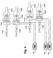
- each telephone circuit 13a, 13b and 13c has one of its two wires connected to the center-tap 37b1, 37b2 and 37b3 of the respective transformer 31b1, 31b2 and 31b3 at the corresponding end of the respective pair and the other wire - to the center-tap 37b4 of the transformer 31b4 at the corresponding end of the common pair.
- N pairs of conductors each pair serving as a data channel, it is possible to similarly provide N-1 phantom channels for telephone service.
- the modules 32a and 32b are stand-alone modules, mechanically separate from other components in the network.
- the hub side module 32a can be integrated, fully or in part, within the hub 16.
- the hub's existing data connection-unit (such as a distribution frame - for connecting thereto all line pairs) is preferably substituted by one that includes module 32a; in addition, a telephone connector is provided, for connecting all telephone lines (whose other ends are connected to their respective center taps in module 32a) to the PABX.
- module 32a can be similarly integrated within PABX 11, whereby an appropriate connection with the hub is provided.
- Fig. 5a shows schematically an arrangement where the computer side module 32b is integrated, fully or in part, within the computer 18a.
- the secondary windings 36 of the transformers 31a1 and 31a2 are connected to receiver and transmitter circuitry 39a and 39b within the computer 18a.
- the ends of the primary windings 35 of the transformers 31a1 and 31a2 are connected to a standard socket outlet 40 for connecting to the network.
- the center-taps 37a1 and 37a2 are connected to a standard telephone outlet 41, enabling connection thereto of a telephone set such as designated 13a in Fig. 3 .
- Fig. 5b shows schematically the complementary arrangement where the module 32b is integrated the telephone set 13a.
- the secondary windings 36 of the transformers 31a1 and 31a2 are connected to a standard outlet 42 for connecting thereto a computer such as designated 18a in Fig. 3 .
- the ends of the primary windings 35 of the transformers 31a1 and 31a2 are connected to a standard socket outlet 43 for connecting to the network.
- the center-taps 37a1 and 37a2 are connected to telephone circuitry 44, within the telephone set 13a.
- the computer side module 32b can be integrated within a wall connector allowing direct or indirect connection to an existing wall socket outlet.
- a wall connector can be constituted by a substitute wall socket having integrated therein a pair of signal transformers and two female outlets for connecting a computer and telephone thereto, respectively.
- the wall connector can be constituted by a plug connector having integrated therein a pair of signal transformers and two female outlets for connecting a computer and telephone thereto, respectively.
- a plug connector allows a computer and telephone to be connected to an existing wall socket outlet without requiring any modification thereto.
- Fig. 6 shows the faceplate of a modified socket outlet 45 according to the invention.
- Two conductor pairs are connected to the outlet at the rear (not shown in the Figure), connected to the primary windings of two signals transformers housed in it (not shown in the Figure).
- the secondary windings of the transformers are connected to RJ-45 data connector 46, while the center taps are connected to the RJ-11 telephony connector 47.
- Such an outlet is physically similar in size, shape, and overall appearance to a standard outlet, so that such an outlet can be substituted for a standard outlet in the building wall. No changes are required in the overall LAN line layout or configuration.
- Such an outlet can easily substitute an existing standard data outlet to thus additionally provide telephony support.
- a conventional outlet has a single female connector having two pairs of wiper contacts connected to the respective twisted-wire pairs for data transmission and reception.
- a computer is plugged into such a conventional outlet via a single male connector (plug) having four pins: two for handling data transmission and two for handling data reception.
- the pins brush against the wiper contacts in the socket outlet, thus establishing electrical connection between the two.
- the invention allows for the conventional outlet to be replaced by a modified outlet having therein a pair of signal transformers, the ends of whose respective primary windings are adapted to be connected to the ends of a respective conductor pair in the network.
- the secondary winding of each signal transformer is connected internally to a respective pair of wiper contacts of a first female connector.
- the ends of both secondary windings are connected to first female connector by means of four wiper contacts in total.
- the respective center-taps of each of the two primary windings are connected to a pair of wiper contacts in a second female connector proximate the first female connector.
- a computer can be connected, via four pins of a suitable jack plug, to the first female connector, while a telephone can be connected, via two pins of a suitable jack plug to the second female connector.
- the two wire pairs 17a1 and 17a2 are routed and connected to such an outlet, which will now comprise two faceplate connectors - a data connector (e.g. RJ-45 for 10baseT) and a telephone connector (e.g. RJ-11).
- FIGs. 7a to 7d show various views of a plug assembly 50 according to the invention for operation in 10BaseT or 100BaseTX environment that allows the invention to be implemented without requiring any modification to the data network or to the existing socket outlet.
- the plug assembly 50 is plugged into a standard socket outlet and is retained therein by means of a latch 51.
- the plug assembly 50 contains the module 32b connected to separate data- and telephony socket outlets 52 and 53 in a similar manner to the modified socket outlet 45 described above with reference to Fig. 6 .
- a standard RJ45 jack plug 54 is connected to the module 32b for mating with the wall outlet when plugged into its socket.
- the jack plug 54 thus includes two pairs of pins each connected to the primary winding of a respective signal transformer within the module 32b.
- the secondary windings of the two signal transformers are connected to respective wiper contacts in the data-telephony socket outlet 52.
- the respective center-taps of each of the primary windings are connected to a pair of wiper contacts in the telephony socket outlet 53 proximate the data-telephony socket outlet 52. Cables from the computer and the telephone set terminate in standard jack plugs that are plugged into the respective data- and telephony socket outlets 52 and 53 within the plug assembly 50.
- the plug assembly 50 obviates the need for any changes to be made to the existing infrastructure.
- 10BaseT and 100BaseTX interfaces often include signal transformers in the line connection circuitry, in order to meet isolation and common-mode rejection requirements.
- additional transformers are not required and the method of the present invention can be implemented by adding center-tap connections to the respective windings of the existing transformers and using them to form a phantom channel, to serve for telephone connection in the manner described above.
- the existing transformers can be substituted by ones with center-taps as specified above.
- the present invention also embraces a method for upgrading an existing local area network (LAN) installation that includes a two-conductor pair cable between two digital devices, to also and simultaneously convey signals between two telephone devices, the method comprising:
Claims (21)
- Circuit (32a) devant être utilisé avec un câblage comprenant une première paire de conducteurs (17a1) portant un premier signal et une seconde paire de conducteurs (17a2) portant un second signal, les première et seconde paires portant en outre en coopération un signal téléphonique analogique sur un canal fantôme, le circuit comprenant :une première connexion pour connexion audit câblage ;une deuxième connexion pour connexion à un premier dispositif (16, 18) ;une troisième connexion (38a, 38b) pour couplage à un dispositif téléphonique (11, 13) ;un premier transformateur (31a1) ayant un enroulement principal (35) et un enroulement secondaire (36), l'enroulement principal ayant une première connexion de prise médiane (37a1), l'enroulement principal étant connecté à ladite première connexion pour connexion à ladite première paire de conducteurs, l'enroulement secondaire étant connecté à ladite deuxième connexion pour connexion audit premier dispositif ;un second transformateur (31a2) ayant un enroulement principal (35) et un enroulement secondaire (36), l'enroulement principal ayant une seconde connexion de prise médiane (37a2), l'enroulement principal étant connecté à ladite première connexion pour connexion à ladite secondaire paire de conducteurs, l'enroulement secondaire étant connecté à ladite seconde connexion pour connexion audit premier dispositif ; etdans lequel les première et seconde connexions de prise médiane sont connectées à ladite troisième connexion pour connexion audit dispositif téléphonique ;
dans lequel :lesdits premier et second signaux sont des signaux de données numériques en série, et dans lequel : ladite première connexion est un connecteur pour transmission de données (54) conçu pour assurer la connexion à un réseau local ; etlesdits premier et second transformateurs sont conçus pour assurer le passage de signaux de données numériques de réseau local. - Module (32) comprenant :un logement (45, 54) logeant le circuit selon la revendication 1,un deuxième connecteur (52, 46) connecté à la deuxième connexion, etun troisième connecteur (53, 47) connecté à la troisième connexion.
- Module selon la revendication 2, dans lequel au moins un desdits connecteurs est choisi dans le groupe RJ-11, RJ-45.
- Module selon la revendication 2 ou 3, dans lequel le connecteur de réseau local (54) est constitué d'un ensemble fiche faisant saillie du logement.
- Module selon l'une quelconque des revendications 2 à 4, étant une embase de sortie combinée.
- Module selon la revendication 5, dimensionné pour se conformer à un connecteur mural existant d'un réseau de communication de données.
- Module selon la revendication 5, dans lequel le connecteur pour transmission de données (54) est constitué d'un ensemble fiche faisant saillie du logement destiné à assurer le couplage avec une sortie de prise d'un réseau de données.
- Module selon l'une quelconque des revendications 2 à 7, dans lequel lesdits premier et second signaux se conforment sensiblement au standard Ethernet IEEE802.3, et lesdits premier et second transformateurs sont opérationnels pour assurer sensiblement le passage desdits signaux basés sur le standard Ethernet IEEE802.3.
- Module selon l'une quelconque des revendications 2 à 8, dans lequel ledit logement peut être fixé directement ou indirectement à une surface d'un bâtiment.
- Module selon l'une quelconque des revendications 2 à 9, pouvant en outre être monté dans une ouverture de paroi ou une cavité de sortie.
- Procédé d'activation d'un câblage comprenant des première et seconde paires de conducteurs (17a1, 17a2) ayant des première et seconde extrémités pour porter respectivement des premier et second signaux entre des première et seconde unités (16, 18a) situées respectivement dans des premier et second emplacements, et pour porter en outre en coopération un signal téléphonique analogique sur un canal fantôme entre deux dispositifs téléphoniques analogiques (11, 13a), le procédé comprenant les étapes consistant à :a) prévoir des premier et deuxième transformateurs (31a1, 31a2) ayant chacun un enroulement principal (35) et un enroulement secondaire (36), chaque enroulement principal ayant une connexion de prise médiane (37a1, 37a2),b) connecter les enroulements principaux desdits premier et deuxième transformateurs respectivement à la première extrémité de chacune desdites première et seconde paires ;c) connecter les enroulements secondaires desdits premier et second transformateurs à une première unité (16) ;d) connecter les connexions de prise médiane desdits premier et second transformateurs à un premier dispositif téléphonique analogique (11) ;e) prévoir des troisième et quatrième transformateurs (31b1, 31b2), ayant chacun un enroulement principal (35) et un enroulement secondaire (36), chaque enroulement principal ayant une connexion de prise médiane ;f) connecter les enroulements principaux desdits troisième et quatrième transformateurs respectivement à la seconde extrémité de chacune desdits première et secondaire paires ;g) connecter les enroulements secondaires desdits troisième et quatrième transformateurs à une seconde unité (18a) ; eth) connecter les connexions de prise médiane desdits troisième et quatrième transformateurs à un second dispositif téléphonique analogique (13a) ;
dans lequel
ledit câblage est un câblage de réseau local dans unbâtiment, et dans lequel lesdits premier et second signaux portés respectivement sur lesdites première et seconde paires sont des signaux de données numériques en série, et dans lequel lesdits première et seconde unités sont des unités de données numériques ; et
lesdits premier, deuxième, troisième et quatrième transformateurs sont conçus pour assurer le passage des signaux de données numériques du réseau local. - Procédé selon la revendication 11, comprenant en outre les étapes consistant à :i) mettre en place un logement ;j) loger au moins un desdits transformateurs dans ledit logement ; etk) prévoir au moins un connecteur (54) pour connexion d'au moins un desdits transformateurs au câblage.
- Procédé selon la revendication 12, dans lequel au moins un desdits connecteurs est un connecteur du commerce.
- Procédé selon la revendication 13, dans lequel le connecteur du commerce est choisi dans le groupe RJ-11, RJ-45.
- Procédé selon l'une quelconque des revendications 12 à 14, dans lequel ledit au moins un connecteur (54) est constitué d'un ensemble fiche faisant saillie du logement.
- Procédé selon l'une quelconque des revendications 12 à 14, dans lequel le logement est sous la forme d'une embase de sortie combinée.
- Procédé selon la revendication 16, dans lequel l'embase de sortie combinée est conçue pour être montée sur paroi et l'au moins un connecteur (54) inclut des connecteurs femelles destinés à loger les conducteurs respectifs du câblage.
- Procédé selon la revendication 16 ou 17, dans lequel l'embase de sortie combinée est dimensionnée pour se conformer à un connecteur de paroi existant du réseau de communication de données.
- Procédé selon l'une quelconque des revendications 11 à 18, dans lequel chacun desdits signaux de données numériques se conforme sensiblement au standard Ethernet IEEE802.3, et lesdits transformateurs sont opérationnels pour assurer sensiblement le passage desdits signaux basés sur le standard Ethernet IEEE802.3.
- Procédé selon l'une quelconque des revendications 11 à 19, dans lequel au moins un desdits transformateurs est inclus dans un logement qui peut être fixé directement ou indirectement à une surface d'un bâtiment.
- Procédé selon l'une quelconque des revendications 11 à 20, dans lequel au moins un desdits transformateurs est inclus dans un logement qui peut être monté dans une ouverture de paroi ou une cavité de sortie.
Priority Applications (1)
| Application Number | Priority Date | Filing Date | Title |
|---|---|---|---|
| EP10154822.0A EP2209293B1 (fr) | 2000-09-21 | 2001-05-01 | Circuit de couplage d'un dispositif d'information et d'un dispositif numérique à un câble de réseau local |
Applications Claiming Priority (3)
| Application Number | Priority Date | Filing Date | Title |
|---|---|---|---|
| US09/666,856 US6961303B1 (en) | 2000-09-21 | 2000-09-21 | Telephone communication system and method over local area network wiring |
| US666856 | 2000-09-21 | ||
| PCT/IL2001/000388 WO2002025920A1 (fr) | 2000-09-21 | 2001-05-01 | Systeme de communication telephonique et procede applique a un cablage de reseau local |
Related Child Applications (1)
| Application Number | Title | Priority Date | Filing Date |
|---|---|---|---|
| EP10154822.0 Division-Into | 2010-02-26 |
Publications (2)
| Publication Number | Publication Date |
|---|---|
| EP1319306A1 EP1319306A1 (fr) | 2003-06-18 |
| EP1319306B1 true EP1319306B1 (fr) | 2010-05-05 |
Family
ID=24675775
Family Applications (2)
| Application Number | Title | Priority Date | Filing Date |
|---|---|---|---|
| EP10154822.0A Expired - Lifetime EP2209293B1 (fr) | 2000-09-21 | 2001-05-01 | Circuit de couplage d'un dispositif d'information et d'un dispositif numérique à un câble de réseau local |
| EP01928176A Expired - Lifetime EP1319306B1 (fr) | 2000-09-21 | 2001-05-01 | Systeme de communication telephonique et procede applique a un cablage de reseau local |
Family Applications Before (1)
| Application Number | Title | Priority Date | Filing Date |
|---|---|---|---|
| EP10154822.0A Expired - Lifetime EP2209293B1 (fr) | 2000-09-21 | 2001-05-01 | Circuit de couplage d'un dispositif d'information et d'un dispositif numérique à un câble de réseau local |
Country Status (12)
| Country | Link |
|---|---|
| US (7) | US6961303B1 (fr) |
| EP (2) | EP2209293B1 (fr) |
| JP (4) | JP4813753B2 (fr) |
| KR (4) | KR100927496B1 (fr) |
| CN (2) | CN1322733C (fr) |
| AT (1) | ATE467310T1 (fr) |
| AU (1) | AU2001255038A1 (fr) |
| CA (2) | CA2423326C (fr) |
| DE (1) | DE60142059D1 (fr) |
| ES (2) | ES2444585T3 (fr) |
| IL (1) | IL154967A0 (fr) |
| WO (1) | WO2002025920A1 (fr) |
Families Citing this family (57)
| Publication number | Priority date | Publication date | Assignee | Title |
|---|---|---|---|---|
| US6480510B1 (en) | 1998-07-28 | 2002-11-12 | Serconet Ltd. | Local area network of serial intelligent cells |
| US6956826B1 (en) | 1999-07-07 | 2005-10-18 | Serconet Ltd. | Local area network for distributing data communication, sensing and control signals |
| US6690677B1 (en) | 1999-07-20 | 2004-02-10 | Serconet Ltd. | Network for telephony and data communication |
| US6549616B1 (en) | 2000-03-20 | 2003-04-15 | Serconet Ltd. | Telephone outlet for implementing a local area network over telephone lines and a local area network using such outlets |
| IL135744A (en) | 2000-04-18 | 2008-08-07 | Mosaid Technologies Inc | Telephone communication system through a single line |
| US6842459B1 (en) | 2000-04-19 | 2005-01-11 | Serconet Ltd. | Network combining wired and non-wired segments |
| IL138517A (en) | 2000-09-17 | 2005-07-25 | Serconet Ltd | System and method for transmission-line termination by signal cancellation, and applications thereof |
| US6961303B1 (en) | 2000-09-21 | 2005-11-01 | Serconet Ltd. | Telephone communication system and method over local area network wiring |
| US7123893B1 (en) * | 2001-04-24 | 2006-10-17 | Bellsouth Intellectual Property Corp. | Wireless frequency re-use determination systems and methods |
| IL144158A (en) | 2001-07-05 | 2011-06-30 | Mosaid Technologies Inc | Socket for connecting an analog telephone to a digital communications network that carries digital voice signals |
| WO2003028181A1 (fr) | 2001-09-25 | 2003-04-03 | Serconet Ltd. | Adaptateur pour le montage d'un premier modele de couvercle sur un second modele de cavite de prise de courant |
| IL161190A0 (en) | 2001-10-11 | 2004-08-31 | Serconet Ltd | Outlet with analog signal adapter, method for use thereof and a network using said outlet |
| GB2384407A (en) * | 2002-01-22 | 2003-07-23 | Mitel Knowledge Corp | Power supply for phantom-feed lan connected device using spare-pair powering |
| DE10221425A1 (de) * | 2002-05-14 | 2003-12-04 | Siemens Ag | Datennetzschnittstelle und Kommunikationseinrichtungen mit Datennetzschnittstelle |
| IL152824A (en) | 2002-11-13 | 2012-05-31 | Mosaid Technologies Inc | A socket that can be connected to and the network that uses it |
| US8098681B2 (en) * | 2003-01-29 | 2012-01-17 | Avaya Inc. | Method and apparatus for dynamic termination of unused wired connection |
| IL154234A (en) | 2003-01-30 | 2010-12-30 | Mosaid Technologies Inc | Method and system for providing dc power on local telephone lines |
| IL154921A (en) | 2003-03-13 | 2011-02-28 | Mosaid Technologies Inc | A telephone system that includes many separate sources and accessories for it |
| IL157787A (en) * | 2003-09-07 | 2010-12-30 | Mosaid Technologies Inc | Modular outlet for data communications network |
| IL159838A0 (en) | 2004-01-13 | 2004-06-20 | Yehuda Binder | Information device |
| IL160417A (en) | 2004-02-16 | 2011-04-28 | Mosaid Technologies Inc | Unit added to the outlet |
| IL161869A (en) | 2004-05-06 | 2014-05-28 | Serconet Ltd | A system and method for carrying a signal originating is wired using wires |
| US20060013246A1 (en) * | 2004-07-13 | 2006-01-19 | International Business Machines Corporation | System, apparatus and method for gigabit ethernet communications over an IBM cabling system |
| US7873058B2 (en) | 2004-11-08 | 2011-01-18 | Mosaid Technologies Incorporated | Outlet with analog signal adapter, a method for use thereof and a network using said outlet |
| IL166445A (en) | 2005-01-23 | 2011-07-31 | Mosaid Technologies Inc | A standard and method for evaluating the termination of a transmission line based on the determination of a typical impedance |
| US7856032B2 (en) | 2005-04-04 | 2010-12-21 | Current Technologies, Llc | Multi-function modem device |
| US7813501B2 (en) * | 2005-10-05 | 2010-10-12 | Mitel Networks Corporation | Midspan power delivery system for reduced emissions |
| US7813451B2 (en) | 2006-01-11 | 2010-10-12 | Mobileaccess Networks Ltd. | Apparatus and method for frequency shifting of a wireless signal and systems using frequency shifting |
| US7852207B2 (en) | 2006-02-14 | 2010-12-14 | Current Technologies, Llc | Method for establishing power line communication link |
| US7596079B2 (en) * | 2006-05-31 | 2009-09-29 | Current Technologies, Llc | System and method for communicating in a multi-unit structure |
| US7602695B2 (en) * | 2006-05-31 | 2009-10-13 | Current Technologies, Llc | System and method for communicating in a multi-unit structure |
| JP2008154033A (ja) * | 2006-12-19 | 2008-07-03 | Nec Infrontia Corp | システム間接続方式およびその無線制御チャネル同期信号共有方法 |
| EP3103791B1 (fr) | 2007-06-27 | 2018-01-31 | Merck Sharp & Dohme Corp. | Dérivés de 4-carboxybenzylamino utilisés comme inhibiteurs de l'histone désacétylase |
| US8594133B2 (en) | 2007-10-22 | 2013-11-26 | Corning Mobileaccess Ltd. | Communication system using low bandwidth wires |
| US20090153487A1 (en) * | 2007-12-12 | 2009-06-18 | Gunther Adam M | Data input device having a plurality of key stick devices for fast typing and method thereof |
| US8175649B2 (en) | 2008-06-20 | 2012-05-08 | Corning Mobileaccess Ltd | Method and system for real time control of an active antenna over a distributed antenna system |
| US20090310520A1 (en) * | 2008-06-13 | 2009-12-17 | Jun Yang | Wideband telephone conference system interface |
| US20100186234A1 (en) | 2009-01-28 | 2010-07-29 | Yehuda Binder | Electric shaver with imaging capability |
| EP2399141A4 (fr) | 2009-02-08 | 2012-08-01 | Corning Mobileaccess Ltd | Système de communication utilisant des câbles transportant des signaux ethernet |
| US20100295782A1 (en) | 2009-05-21 | 2010-11-25 | Yehuda Binder | System and method for control based on face ore hand gesture detection |
| PL2589051T3 (pl) * | 2010-06-29 | 2018-10-31 | Orange | Gniazdo telefoniczne i adapter do szybkiej sieci lokalnej |
| DE112010005806T5 (de) | 2010-09-22 | 2013-05-16 | Hewlett-Packard Development Company, L.P. | Modulare Schnittstellensysteme und Verfahren |
| EP2509250B1 (fr) * | 2011-04-08 | 2013-12-11 | Alcatel Lucent | Dispositif de combinaison pour signaux de mode fantôme DSL dans un système de télécommunication |
| EP2829152A2 (fr) | 2012-03-23 | 2015-01-28 | Corning Optical Communications Wireless Ltd. | Puce(s) de circuit intégré à radiofréquence (rfic) servant à fournir des fonctionnalités de système d'antenne à répartition, et composants, systèmes, et procédés connexes |
| US9274992B2 (en) * | 2013-07-19 | 2016-03-01 | Lattice Semiconductor Corporation | Cable with circuitry for communicating performance information |
| US9184960B1 (en) | 2014-09-25 | 2015-11-10 | Corning Optical Communications Wireless Ltd | Frequency shifting a communications signal(s) in a multi-frequency distributed antenna system (DAS) to avoid or reduce frequency interference |
| EP3266108B1 (fr) * | 2015-03-02 | 2019-08-14 | British Telecommunications public limited company | Procédé et appareil pour transmettre des données dans un mode différentiel et fantôme dans un dsl vectorisé |
| CN109075813B (zh) | 2016-03-31 | 2021-08-20 | 英国电讯有限公司 | 经多个线对发送数据的方法、发送器、接收器和收发系统 |
| US10574292B2 (en) | 2016-08-29 | 2020-02-25 | British Telecommunications Public Limited Company | Method and apparatus for transmitting data over metallic wire pairs |
| GB2557893B (en) * | 2016-09-29 | 2020-03-11 | British Telecomm | Method and apparatus for transmitting data from a transmitter device to one or more receiver devices |
| EP3301898A1 (fr) * | 2016-09-29 | 2018-04-04 | British Telecommunications public limited company | Procédé et appareil pour transmettre des données depuis un dispositif émetteur à un ou plusieurs dispositifs de réception |
| WO2018178400A1 (fr) | 2017-03-31 | 2018-10-04 | British Telecommunications Public Limited Company | Procédé et appareil de transmission de signaux sur des liaisons filaires |
| EP3577890A1 (fr) | 2017-03-31 | 2019-12-11 | British Telecommunications Public Limited Company | Procédé et appareil d'émission de signaux sur des connexions filaires |
| WO2018178209A1 (fr) | 2017-03-31 | 2018-10-04 | British Telecommunications Public Limited Company | Procédé et appareil d'émission de signaux sur des connexions filaires |
| EP3577775B1 (fr) | 2017-03-31 | 2020-11-18 | British Telecommunications Public Limited Company | Procédé et appareil de transmission de signaux sur des connexions filaires |
| BR102018014515A2 (pt) * | 2018-07-16 | 2019-01-22 | Elsys Equipamentos Eletrônicos Ltda | dispositivo injetor e extrator e método de transmissão de sinal telefônico analógico, simultaneamente a sinais de dados e alimentação em mesmo cabo de rede |
| KR101988918B1 (ko) * | 2018-11-16 | 2019-06-13 | (주)자람테크놀로지 | 광대역 통신을 위한 단자대 배선 연결 장치 |
Family Cites Families (262)
| Publication number | Priority date | Publication date | Assignee | Title |
|---|---|---|---|---|
| FR2041544A5 (fr) | 1969-04-29 | 1971-01-29 | Schlumberger Cie N | |
| US3717858A (en) | 1970-08-12 | 1973-02-20 | D Hadden | Two conductor telemetering system |
| BE793053A (fr) * | 1971-12-20 | 1973-06-20 | Siemens Ag | Montage pour des lignes d'abonnes comportant deux lignes bifilaires symetriques pour la transmission supplementaire de signaux, en particulierpour des video-telephones |
| US3806814A (en) | 1972-04-26 | 1974-04-23 | Hughes Aircraft Co | Phantom subscriber |
| GB1488304A (en) | 1974-06-20 | 1977-10-12 | Yukogawa Electric Works Ltd | Signal transmission system |
| US4173714A (en) | 1977-06-03 | 1979-11-06 | Tie/Communications, Inc. | Communication circuit with combined power feed and data transmission over a phantom channel |
| US4272759A (en) | 1978-06-23 | 1981-06-09 | Xerox Corporation | 16 Bit analog to digital converter |
| US4303993A (en) | 1979-10-10 | 1981-12-01 | Honeywell Information Systems Inc. | Memory present apparatus |
| US4389694A (en) | 1980-10-08 | 1983-06-21 | Pemco Corporation | Cable continuity monitoring system |
| KR870000486B1 (ko) | 1981-02-20 | 1987-03-11 | 금성통신 주식회사 | 선로의 사용을 최소로 한 전력전달 및 평형 방식의 데이타 송수신 회로 |
| US4463341A (en) | 1981-06-01 | 1984-07-31 | Aisin Seiki Kabushiki Kaisha | Single conductor multi-frequency electric wiring system for vehicles |
| US4477896A (en) | 1981-10-02 | 1984-10-16 | Aker Eric M | Single-wire data transmission system having bidirectional data synchronization, and D.C. power for remote units |
| EP0082889B1 (fr) * | 1981-12-29 | 1985-06-05 | International Business Machines Corporation | Méthode et dispositif pour l'acquisition d'une adresse locale par une station dans un système de communication |
| US4467314A (en) | 1982-03-29 | 1984-08-21 | Westinghouse Electric Corp. | Electric utility communication system with field installation terminal and load management terminal with remotely assignable unique address |
| US4535401A (en) | 1982-06-30 | 1985-08-13 | Texas Instruments Incorporated | Apparatus and method for providing power from master controller to subcontrollers and data communication therebetween |
| US5894661A (en) * | 1995-03-15 | 1999-04-20 | Sumitomo Wiring Systems, Ltd. | Connector manufacturing method |
| US4551721A (en) | 1983-10-07 | 1985-11-05 | Honeywell Inc. | Method for initializing a token-passing local-area network |
| US4672605A (en) | 1984-03-20 | 1987-06-09 | Applied Spectrum Technologies, Inc. | Data and voice communications system |
| US4633217A (en) | 1984-06-04 | 1986-12-30 | Yamatake Honeywell | Communication apparatus |
| US4639714A (en) | 1984-12-21 | 1987-01-27 | Ferranti Subsea Systems, Ltd. | Combined power and control signal transmission system |
| JPS61187846A (ja) * | 1985-02-15 | 1986-08-21 | 横河メディカルシステム株式会社 | マトリツクススイツチ回路 |
| US5021779A (en) | 1985-08-14 | 1991-06-04 | Michael Bisak | Security device |
| US4815106A (en) | 1986-04-16 | 1989-03-21 | Adaptive Networks, Inc. | Power line communication apparatus |
| US4761646A (en) | 1986-05-20 | 1988-08-02 | International Business Machines Corporation | Method and system for addressing and controlling a network of modems |
| US4733389A (en) | 1986-07-28 | 1988-03-22 | Xerox Corporation | Drop cable for a local area network |
| US4795448A (en) | 1986-08-08 | 1989-01-03 | Haemonetics Corporation | Suction collection system |
| US4806905A (en) | 1986-10-01 | 1989-02-21 | Honeywell Inc. | Transmitter for transmitting on a two-wire transmitting line |
| US5457629A (en) | 1989-01-31 | 1995-10-10 | Norand Corporation | Vehicle data system with common supply of data and power to vehicle devices |
| US4736367A (en) | 1986-12-22 | 1988-04-05 | Chrysler Motors Corporation | Smart control and sensor devices single wire bus multiplex system |
| US4807225A (en) | 1987-02-02 | 1989-02-21 | American Telephone And Telegraph Company, At&T Technologies, Inc. | Telephone line carrier system |
| US4785448A (en) | 1987-02-25 | 1988-11-15 | Reichert Andrew R | System for communicating digital data on a standard office telephone system |
| US4803485A (en) | 1987-03-23 | 1989-02-07 | Amp Incorporated | Lan communication system and medium adapter for use therewith |
| US4890102A (en) | 1987-05-26 | 1989-12-26 | Cabletron, Inc. | Visual display for communication network monitoring and troubleshooting |
| CA1297157C (fr) | 1987-07-13 | 1992-03-10 | Geoffrey Nelson Bowling | Systeme d'alimentation electrique et de communication programmable a boucle fermee |
| US4799211A (en) | 1987-07-23 | 1989-01-17 | Digital Equipment Corporation | Apparatus and method for storing performance parameters of local area network system members |
| US4766402A (en) | 1987-08-06 | 1988-08-23 | 3Com Corporation | Apparatus for matching unbalanced R. F. baseband signals to balanced signals on a twisted two-wire line |
| US4901218A (en) | 1987-08-12 | 1990-02-13 | Renishaw Controls Limited | Communications adaptor for automated factory system |
| FR2620291B1 (fr) | 1987-09-09 | 1989-11-24 | Telephonie Ind Commerciale | Systeme et dispositif de protection et de telealimentation pour equipement connecte par deux transformateurs a une liaison de transmission a quatre fils |
| US4918690A (en) | 1987-11-10 | 1990-04-17 | Echelon Systems Corp. | Network and intelligent cell for providing sensing, bidirectional communications and control |
| US5025443A (en) | 1988-02-24 | 1991-06-18 | Integrated Network Corporation | Digital data over voice communication |
| US4924492A (en) | 1988-03-22 | 1990-05-08 | American Telephone And Telegraph Company | Method and apparatus for wideband transmission of digital signals between, for example, a telephone central office and customer premises |
| DE3828272A1 (de) | 1988-08-19 | 1990-03-01 | Siemens Ag | Anordnung zum uebertragen von daten und einer versorgungsspannung ueber eine busleitung |
| US5032819A (en) | 1988-10-24 | 1991-07-16 | Murata Mfg. Co., Ltd. | Data communications system |
| NO303200B1 (no) | 1988-11-04 | 1998-06-08 | Merlin Gerin | Bygningsteknisk styringsenhet med totrÕds data- og kraftforsyningslinje |
| US5034531A (en) | 1988-12-23 | 1991-07-23 | Schering Corporation | Fused polycyclic pyranyl compounds as antiviral agents |
| US4992774A (en) | 1989-01-27 | 1991-02-12 | Mccullough Robert K | Method for powering remote visual displays and allowing for data exchange over the same wire pair |
| US4926158A (en) | 1989-02-01 | 1990-05-15 | Zeigler John R | Powered communication link |
| US4937811A (en) | 1989-02-24 | 1990-06-26 | General Instrument Corporation | Communication network |
| US5033062A (en) | 1989-05-30 | 1991-07-16 | Morrow Stephen E | Digital modem |
| US5065133A (en) * | 1989-08-25 | 1991-11-12 | The Siemon Company | Method and apparatus converting digital signals to analog signals and simultaneous transmission of ac power and signals over wire conductors |
| FR2651398B1 (fr) | 1989-08-31 | 1995-08-25 | Alcatel Business Systems | Agencement d'alimentation pour terminal telephonique et/ou telematique. |
| US5121482A (en) | 1989-09-11 | 1992-06-09 | Hewlett-Packard Company | Circuit and method for automatic input-output configuration through local area network detection |
| US5089927A (en) | 1989-10-12 | 1992-02-18 | Northern Telecom Limited | Power feed circuit for digital communications terminal equipment |
| US5164960A (en) * | 1990-02-15 | 1992-11-17 | Advanced Micro Devices Inc. | Medium attachment unit for use with twisted pair local area network |
| JPH03296359A (ja) | 1990-04-16 | 1991-12-27 | Fujitsu Ltd | Isdnインタフェース回路 |
| GB9011970D0 (en) | 1990-05-29 | 1990-07-18 | Leigh Stewart Prod | Electrical control system for,for example,an air spa bath |
| GB2249460B (en) | 1990-09-19 | 1994-06-29 | Intel Corp | Network providing common access to dissimilar hardware interfaces |
| US5274631A (en) | 1991-03-11 | 1993-12-28 | Kalpana, Inc. | Computer network switching system |
| US5148144A (en) | 1991-03-28 | 1992-09-15 | Echelon Systems Corporation | Data communication network providing power and message information |
| FR2684250B1 (fr) | 1991-11-27 | 1994-04-01 | Merlin Gerin | Systeme de distribution d'energie electrique de haute qualite. |
| CN2106457U (zh) * | 1991-11-28 | 1992-06-03 | 深圳华强电脑厂 | 动态信息自动电话计费机 |
| US5285477A (en) | 1991-12-18 | 1994-02-08 | At&T Bell Laboratories | Balanced line driver for local area networks or the like |
| US5301208A (en) * | 1992-02-25 | 1994-04-05 | The United States Of America As Represented By The Secretary Of The Air Force | Transformer bus coupler |
| JPH05240137A (ja) | 1992-03-02 | 1993-09-17 | Mitsubishi Electric Corp | 内燃機関用気筒識別装置 |
| DE4210023A1 (de) * | 1992-03-27 | 1993-09-30 | Sel Alcatel Ag | Digitales Nachrichtenübertragungssystem mit elektrischen symmetrischen Zweidraht-Leitungen unter Verwendung von Phantomkreisen |
| IT1255289B (it) * | 1992-05-26 | 1995-10-26 | Ansaldo Spa | Metodo e circuito per il comando della commutazione di un invertitore in "sliding-mode" e in pwm con tensione di uscita a tre livelli |
| DE69333764T2 (de) | 1992-09-22 | 2006-03-23 | The Furukawa Electric Co., Ltd. | Multiplexübertragungseinrichtung |
| MX9306152A (es) | 1992-10-05 | 1994-05-31 | Fisher Controls Int | Sistema de comunicacion y metodo. |
| US5368041A (en) | 1992-10-15 | 1994-11-29 | Aspect Medical Systems, Inc. | Monitor and method for acquiring and processing electrical signals relating to bodily functions |
| GB9222205D0 (en) * | 1992-10-22 | 1992-12-02 | Norweb Plc | Low voltage filter |
| US5414708A (en) | 1992-12-01 | 1995-05-09 | Farallon Computing, Inc. | Method and apparatus for connecting nodes for a computer network |
| US5406260A (en) | 1992-12-18 | 1995-04-11 | Chrimar Systems, Inc. | Network security system for detecting removal of electronic equipment |
| US5295869A (en) | 1992-12-18 | 1994-03-22 | The Siemon Company | Electrically balanced connector assembly |
| US5469150A (en) | 1992-12-18 | 1995-11-21 | Honeywell Inc. | Sensor actuator bus system |
| FR2700085B1 (fr) | 1992-12-30 | 1995-02-24 | Cit Alcatel | Dispositif de téléalimentation pour équipement électronique. |
| US5579486A (en) | 1993-01-14 | 1996-11-26 | Apple Computer, Inc. | Communication node with a first bus configuration for arbitration and a second bus configuration for data transfer |
| US5483656A (en) | 1993-01-14 | 1996-01-09 | Apple Computer, Inc. | System for managing power consumption of devices coupled to a common bus |
| BR9300603A (pt) | 1993-02-17 | 1994-10-04 | Petroleo Brasileiro Sa | Sistema integrado para transmissão de força e sinal |
| SG44916A1 (en) * | 1993-03-15 | 1997-12-19 | Koninkl Philips Electronics Nv | A telecommunication system and a linecard |
| US5438678A (en) | 1993-03-23 | 1995-08-01 | Smith; Peter L. | Self-powered computer accessory device for power extraction from attached data signals and method of operating thereof |
| US5347549A (en) | 1993-04-20 | 1994-09-13 | Echelon Corporation | Method and apparatus for interfacing between a twisted pair and an intelligent cell |
| US5491402A (en) | 1993-07-20 | 1996-02-13 | Echelon Corporation | Apparatus and method for providing AC isolation while supplying DC power |
| US5391932A (en) | 1993-07-20 | 1995-02-21 | Echelon Corporation | Source power coupler |
| JPH07154389A (ja) * | 1993-07-28 | 1995-06-16 | Internatl Business Mach Corp <Ibm> | データ・ポート・エクスパンダ |
| US5644286A (en) | 1993-10-04 | 1997-07-01 | Lockheed Martin Corporation | Power bus digital communication system |
| US5661634A (en) | 1993-11-09 | 1997-08-26 | Fujitsu Limited | Information processing system using portable terminal unit and data communication adapter therefor |
| JPH07147588A (ja) * | 1993-11-25 | 1995-06-06 | Matsushita Electric Works Ltd | ハブ間の簡易管理情報伝送システム |
| US5635896A (en) | 1993-12-27 | 1997-06-03 | Honeywell Inc. | Locally powered control system having a remote sensing unit with a two wire connection |
| JPH07212506A (ja) | 1994-01-14 | 1995-08-11 | Fujitsu Ltd | 端末給電方式 |
| US6175556B1 (en) * | 1994-06-06 | 2001-01-16 | International Business Machines Corporation | Remote powered ethernet repeater |
| US5525962A (en) | 1994-06-23 | 1996-06-11 | Pittway Corporation | Communication system and method |
| US6377874B1 (en) * | 1994-09-07 | 2002-04-23 | Spd Technologies Inc. | Power distribution system including integrated power node control center |
| US5517172A (en) | 1994-09-19 | 1996-05-14 | Chiu; Manfred F. | Method and apparatus for powering and signaling over a single wire pair |
| JPH08148359A (ja) * | 1994-11-18 | 1996-06-07 | Tdk Corp | Lan用コネクタ |
| US6033101A (en) * | 1994-12-07 | 2000-03-07 | Antec Corporation | Cable television radio frequency and AC Power multitap |
| US5652893A (en) | 1994-12-13 | 1997-07-29 | 3Com Corporation | Switching hub intelligent power management |
| US5546385A (en) | 1995-01-19 | 1996-08-13 | Intel Corporation | Flexible switching hub for a communication network |
| WO1996023377A1 (fr) | 1995-01-27 | 1996-08-01 | Intecom, Incorporated | Systeme multimedia ayant une source d'alimentation centrale et un sous-systeme de distribution |
| US5680397A (en) * | 1995-03-13 | 1997-10-21 | International Business Machines Corporation | Multi-port LAN switch for a token-ring network |
| EP0815682B1 (fr) | 1995-03-16 | 2002-01-23 | Telecommunications Research laboratories | Mise en reseau d'ordinateurs avec utilisation partagee de lignes telephoniques vocales |
| US5610922A (en) | 1995-03-20 | 1997-03-11 | Raychem Corporation | Voice plus 4-wire DDS multiplexer |
| JP2962223B2 (ja) * | 1995-03-27 | 1999-10-12 | 日本電気株式会社 | 統合伝送装置 |
| SG75787A1 (en) * | 1995-03-27 | 2000-10-24 | Nec Corp | Compound transmission system for compounding lan and other communication channels |
| DE19514043A1 (de) | 1995-04-13 | 1996-10-17 | Sel Alcatel Ag | Lokales Netz für den Einsatz in der Bürokommunikation und Schaltungsanordnung dafür |
| JP3264827B2 (ja) | 1995-07-26 | 2002-03-11 | 株式会社エヌ・ティ・ティ・データ | Lanテスタ |
| US5610552A (en) | 1995-07-28 | 1997-03-11 | Rosemount, Inc. | Isolation circuitry for transmitter electronics in process control system |
| US5748634A (en) | 1995-09-14 | 1998-05-05 | Level One Communications, Inc. | Method and apparatus for implementing a two-port ethernet bridge using a semaphoring technique |
| AUPN547695A0 (en) | 1995-09-15 | 1995-10-12 | H.P.M. Industries Pty Limited | Electrical control system |
| US5689230A (en) | 1995-11-09 | 1997-11-18 | Motoral, Inc. | Energy monitoring and control system using reverse transmission on AC line |
| GB9524948D0 (en) | 1995-12-06 | 1996-02-07 | Int Computers Ltd | Combined data and power transmission |
| US5777769A (en) | 1995-12-28 | 1998-07-07 | Lucent Technologies Inc. | Device and method for providing high speed data transfer through a drop line of a power line carrier communication system |
| JPH09274972A (ja) * | 1996-02-05 | 1997-10-21 | Cable Tec Japan:Kk | ビデオ信号伝送用接続器、並びに該接続器を備えたビデオ信号伝送装置及びビデオ信号伝送システム |
| US5684826A (en) | 1996-02-08 | 1997-11-04 | Acex Technologies, Inc. | RS-485 multipoint power line modem |
| US6301527B1 (en) | 1996-04-03 | 2001-10-09 | General Electric Company | Utilities communications architecture compliant power management control system |
| US5815681A (en) | 1996-05-21 | 1998-09-29 | Elonex Plc Ltd. | Integrated network switching hub and bus structure |
| US5805597A (en) | 1996-06-04 | 1998-09-08 | National Semiconductor Corporation | Method and apparatus for providing low power basic telephony type service over a twisted pair ethernet physical layer |
| US5796965A (en) | 1996-06-14 | 1998-08-18 | Texas Instruments Incorporated | Intelligent power circuit for external data drive |
| US5799196A (en) | 1996-07-02 | 1998-08-25 | Gateway 2000, Inc. | Method and apparatus of providing power management using a self-powered universal serial bus (USB) device |
| JP2836592B2 (ja) * | 1996-07-19 | 1998-12-14 | 日本電気株式会社 | 光送受信器およびその光送受信器を用いたネットワーク |
| FR2752126B1 (fr) | 1996-07-31 | 1999-04-09 | Gandar Marc | Systeme de telealimentation d'elements connectes a un reseau |
| US5859596A (en) | 1996-08-30 | 1999-01-12 | Csi Technology, Inc. | Switchyard equipment monitoring system and communications network therefor |
| IL119454A (en) | 1996-10-21 | 2002-07-25 | Serconet Ltd | Distributed serial control system |
| US5990577A (en) | 1996-11-01 | 1999-11-23 | Allied Telesis K. K. | Hub for local area network with backup power supply system |
| US5960066A (en) | 1996-11-07 | 1999-09-28 | Lucent Technologies, Inc. | Method and apparatus for using telephone house wiring for voice/data network |
| JPH10164668A (ja) * | 1996-11-29 | 1998-06-19 | Canon Inc | データ通信システム及びデータ通信装置並びにデータ通信制御プログラムを記録した記録媒体 |
| US5896443A (en) | 1997-01-10 | 1999-04-20 | Intel Corporation | Phone line computer networking |
| US6026078A (en) | 1997-02-05 | 2000-02-15 | Nortel Networks Corporation | Apparatus and method for providing multiple network port configurations |
| EP0858174A3 (fr) | 1997-02-11 | 2002-09-04 | Philips Patentverwaltung GmbH | Procédé et système pour transmèttre des données et de l'énergie |
| SE9700633L (sv) * | 1997-02-21 | 1998-03-16 | Mecel Ab | Metod och arrangemang för kombinerad data och kraftöverföring på kommunikationsbussar |
| EP0863640A3 (fr) * | 1997-03-04 | 2005-09-21 | Texas Instruments Incorporated | Dispositif d'interface perfectionné pour la couche physique |
| US5884086A (en) | 1997-04-15 | 1999-03-16 | International Business Machines Corporation | System and method for voltage switching to supply various voltages and power levels to a peripheral device |
| US6125448A (en) | 1997-05-02 | 2000-09-26 | 3Com Corporation | Power subsystem for a communication network containing a power bus |
| US5939801A (en) | 1997-05-05 | 1999-08-17 | Bouffard; Donald M. | Remote d.c. power supply with automatic backup power feature |
| US6449348B1 (en) | 1997-05-29 | 2002-09-10 | 3Com Corporation | Power transfer apparatus for use by network devices including telephone equipment |
| US6587454B1 (en) | 1997-05-29 | 2003-07-01 | 3Com Corporation | Network adaptor for telephone and data traffic |
| US5994998A (en) | 1997-05-29 | 1999-11-30 | 3Com Corporation | Power transfer apparatus for concurrently transmitting data and power over data wires |
| CN1258412A (zh) * | 1997-05-30 | 2000-06-28 | 凯斯公司 | 双绞线通信系统 |
| US5828293A (en) | 1997-06-10 | 1998-10-27 | Northern Telecom Limited | Data transmission over a power line communications system |
| US5991885A (en) | 1997-06-11 | 1999-11-23 | Clarinet Systems, Inc. | Method and apparatus for detecting the presence of a remote device and providing power thereto |
| US5944831A (en) | 1997-06-13 | 1999-08-31 | Dell Usa, L.P. | Power management apparatus and method for managing power application to individual circuit cards |
| US5930340A (en) | 1997-07-07 | 1999-07-27 | Advanced Micro Devices | Device and method for isolating voice and data signals on a common carrier |
| KR100262518B1 (ko) | 1997-07-09 | 2000-08-01 | 윤종용 | 시스템상태를감지할수있는전원분배유닛 |
| JPH1169392A (ja) * | 1997-08-15 | 1999-03-09 | Nec Corp | 交換機加入者線路を利用した局給電方式 |
| US6016038A (en) | 1997-08-26 | 2000-01-18 | Color Kinetics, Inc. | Multicolored LED lighting method and apparatus |
| US6086390A (en) | 1997-10-24 | 2000-07-11 | Haut; David | Flush/recessable junction device |
| US5934917A (en) * | 1997-10-24 | 1999-08-10 | Haut; David | Flush/recessable junction device |
| US6055633A (en) * | 1997-10-28 | 2000-04-25 | Honeywell Inc. | Method of reprogramming memories in field devices over a multidrop network |
| WO1999026330A2 (fr) | 1997-11-17 | 1999-05-27 | Lifestyle Technologies | Systeme d'alimentation polyvalent |
| US6389139B1 (en) * | 1997-11-18 | 2002-05-14 | Dana Innovations | Powered volume control for distributed audio system |
| US6038457A (en) * | 1997-12-05 | 2000-03-14 | Motorola, Inc. | Apparatus and method for detecting and powering an accessory |
| WO1999036984A1 (fr) * | 1998-01-14 | 1999-07-22 | Int Labs, Inc. | Procede et appareil permettant de transmettre de multiples signaux electriques a largeurs de bande importantes |
| US6049471A (en) * | 1998-02-11 | 2000-04-11 | Powerdsine Ltd. | Controller for pulse width modulation circuit using AC sine wave from DC input signal |
| US5828558A (en) | 1998-02-11 | 1998-10-27 | Powerdsine, Ltd. | PWN controller use with open loop flyback type DC to AC converter |
| US6114632A (en) | 1998-03-05 | 2000-09-05 | Planas, Sr.; Alberto E. | Integrated power and data communication hybrid cable assembly for local area computer network |
| US6134666A (en) | 1998-03-12 | 2000-10-17 | Cisco Technology, Inc. | Power supervisor for electronic modular system |
| US6115468A (en) | 1998-03-26 | 2000-09-05 | Cisco Technology, Inc. | Power feed for Ethernet telephones via Ethernet link |
| DE19813955A1 (de) | 1998-03-28 | 1999-09-30 | Telefunken Microelectron | Verfahren zur Energie- und Datenübertragung in einem Bussystem für Insassenschutzeinrichtungen |
| US6115755A (en) * | 1998-04-09 | 2000-09-05 | Novaweb Technologies, Inc. | Integrated apparatus for interfacing several computers to the internet through a single connection |
| WO1999053627A1 (fr) | 1998-04-10 | 1999-10-21 | Chrimar Systems, Inc. Doing Business As Cms Technologies | Systeme de communication avec un equipement electronique sur un reseau |
| US6366143B1 (en) * | 1998-05-01 | 2002-04-02 | Kye Systems Corp. | Power shut-off and recovery circuit for data communication devices |
| US6049881A (en) * | 1998-05-08 | 2000-04-11 | International Business Machines Corporation | Power adapter for powering a remote device through a computer data port |
| US5973942A (en) | 1998-07-10 | 1999-10-26 | Rosemount Inc. | Start up circuit for DC powered field instrument |
| US6480510B1 (en) * | 1998-07-28 | 2002-11-12 | Serconet Ltd. | Local area network of serial intelligent cells |
| JP3383590B2 (ja) * | 1998-08-19 | 2003-03-04 | 沖電気工業株式会社 | Lan対応電話端末への給電システム |
| US6396391B1 (en) * | 1998-08-27 | 2002-05-28 | Serconet Ltd. | Communications and control network having multiple power supplies |
| US6141763A (en) | 1998-09-01 | 2000-10-31 | Hewlett-Packard Company | Self-powered network access point |
| US6095867A (en) | 1998-09-21 | 2000-08-01 | Rockwell Technologies, Llc | Method and apparatus for transmitting power and data signals via a network connector system including integral power capacitors |
| JP3277901B2 (ja) * | 1998-10-13 | 2002-04-22 | ヤマハ株式会社 | 通信装置 |
| US6348874B1 (en) * | 1998-10-14 | 2002-02-19 | Agilent Technologies, Inc. | Power distribution to nodes in a distributed system |
| US6522515B1 (en) * | 1999-01-08 | 2003-02-18 | Littelfuse, Inc. | Data and power connector port |
| US6643566B1 (en) | 1999-01-12 | 2003-11-04 | Powerdsine Ltd. | System for power delivery over data communication cabling infrastructure |
| US7046983B2 (en) * | 1999-08-02 | 2006-05-16 | Powerdsine, Ltd. | Integral board and module for power over LAN |
| US6473608B1 (en) | 1999-01-12 | 2002-10-29 | Powerdsine Ltd. | Structure cabling system |
| US6393607B1 (en) * | 1999-01-27 | 2002-05-21 | Scientific-Atlanta, Inc. | AC port device for cable television tap |
| US6188314B1 (en) * | 1999-02-03 | 2001-02-13 | Trw Inc. | Energy distribution and communication system and method utilizing a communication message frame for a multi-device vehicle occupant protection system |
| JP2000253102A (ja) * | 1999-02-25 | 2000-09-14 | Kaga Inc | 通信コンセント及び情報通信用宅内配線 |
| US6218930B1 (en) * | 1999-03-10 | 2001-04-17 | Merlot Communications | Apparatus and method for remotely powering access equipment over a 10/100 switched ethernet network |
| US6553076B1 (en) * | 1999-03-15 | 2003-04-22 | Actpro International Limited | Mixed mode transceiver digital control network and collision-free communication method |
| US6470401B1 (en) | 1999-03-18 | 2002-10-22 | C4Si, Inc. | School computer system having simplified computer devices for classroom distribution |
| US6310781B1 (en) | 1999-03-31 | 2001-10-30 | Cisco Technology, Inc. | Connection pin layout for connecting integrated magnetics modules to a printed circuit board |
| US6640308B1 (en) | 1999-04-16 | 2003-10-28 | Invensys Systems, Inc. | System and method of powering and communicating field ethernet device for an instrumentation and control using a single pair of powered ethernet wire |
| US6658109B1 (en) | 1999-06-22 | 2003-12-02 | Charles Industries, Inc. | Method and apparatus for supplying power to a twisted pair wire on a telecommunications modem transmission link |
| US6956826B1 (en) * | 1999-07-07 | 2005-10-18 | Serconet Ltd. | Local area network for distributing data communication, sensing and control signals |
| US6690677B1 (en) * | 1999-07-20 | 2004-02-10 | Serconet Ltd. | Network for telephony and data communication |
| US6571181B1 (en) * | 1999-08-11 | 2003-05-27 | Broadcom Corporation | System and method for detecting a device requiring power |
| US6762675B1 (en) | 1999-09-27 | 2004-07-13 | Cisco Technology, Inc. | Method and apparatus for remote powering of device connected to network |
| US6546494B1 (en) * | 1999-10-06 | 2003-04-08 | Nortel Networks Corporation | Providing power to a device over a network transmission medium |
| DE19950655C2 (de) * | 1999-10-21 | 2001-08-16 | Telefunken Microelectron | Verfahren zur auf eine Versorgungsgleichspannung aufgelagerten Signalübertragung in einem Bussystem |
| EP1100226B1 (fr) * | 1999-11-04 | 2010-02-17 | Alcatel Lucent | Procédé de téléalimentation d'un terminal dans un réseau local |
| US6535983B1 (en) * | 1999-11-08 | 2003-03-18 | 3Com Corporation | System and method for signaling and detecting request for power over ethernet |
| GB2356326B (en) | 1999-11-12 | 2003-12-24 | Mitel Corp | Power supply for ethernet lan connected telephone |
| ATE293256T1 (de) * | 2000-01-11 | 2005-04-15 | Input Output Inc | Digitale zweileiter-zweirichtungs-schnittstelle für seismische telemetrie |
| US6496103B1 (en) | 2000-02-04 | 2002-12-17 | Congruency Inc. | Device, system and method for secure |
| WO2001060029A1 (fr) * | 2000-02-08 | 2001-08-16 | Cetacean Networks, Inc. | Accessoire de haut-parleur destine a un telephone |
| US6549616B1 (en) * | 2000-03-20 | 2003-04-15 | Serconet Ltd. | Telephone outlet for implementing a local area network over telephone lines and a local area network using such outlets |
| IL135744A (en) * | 2000-04-18 | 2008-08-07 | Mosaid Technologies Inc | Telephone communication system through a single line |
| US6842459B1 (en) * | 2000-04-19 | 2005-01-11 | Serconet Ltd. | Network combining wired and non-wired segments |
| SE518378C2 (sv) | 2000-05-12 | 2002-10-01 | Macab Ab | Kommunikationsenhet för datanätsacces via kabeltevenät |
| FR2810485B1 (fr) | 2000-06-19 | 2002-09-06 | Cit Alcatel | Procede pour reinitialiser des terminaux raccordes a un reseau local, et dispositif pour la mise en oeuvre de ce procede |
| US6701443B1 (en) * | 2000-06-19 | 2004-03-02 | Cisco Technology, Inc. | Methods and apparatus for discovering a powerability condition of a computer network |
| US6541878B1 (en) * | 2000-07-19 | 2003-04-01 | Cisco Technology, Inc. | Integrated RJ-45 magnetics with phantom power provision |
| IL138517A (en) * | 2000-09-17 | 2005-07-25 | Serconet Ltd | System and method for transmission-line termination by signal cancellation, and applications thereof |
| US6961303B1 (en) | 2000-09-21 | 2005-11-01 | Serconet Ltd. | Telephone communication system and method over local area network wiring |
| FR2815215B1 (fr) | 2000-10-05 | 2003-01-31 | Cit Alcatel | Terminal apte a etre alimente localement et a etre telealimente par une liaison le reliant a un reseau local |
| US6448899B1 (en) | 2000-10-25 | 2002-09-10 | Nortel Networks Limited | Power indicating ethernet outlet and method therefor |
| US6804351B1 (en) | 2000-11-09 | 2004-10-12 | Cisco Technology, Inc. | Method and apparatus for detecting a compatible phantom powered device using common mode signaling |
| US6738641B1 (en) * | 2000-11-22 | 2004-05-18 | Toshiba America Information Systems, Inc. | Distributed transceiver for wireless communication system |
| US7447307B2 (en) * | 2000-11-29 | 2008-11-04 | Cisco Technology, Inc. | Unpowered twisted pair loopback circuit for differential mode signaling |
| FR2819364B1 (fr) | 2001-01-08 | 2003-04-11 | Cit Alcatel | Dispositif de telealementation d'uin terminal dans un reseau de telecommunication, concentrateur, et repeteur comportant un tel dispositif |
| DE60116246T2 (de) | 2001-01-29 | 2006-07-13 | Ford Global Technologies, LLC, Dearborn | Federvorrichtung |
| US6800957B2 (en) | 2001-02-06 | 2004-10-05 | General Electric Company | Electronic distribution system for 36V automobiles |
| JP2002252731A (ja) | 2001-02-26 | 2002-09-06 | Nec Eng Ltd | 電話機用電源回路 |
| US6459275B1 (en) | 2001-02-28 | 2002-10-01 | Avaya Technology Corp. | Detection of devices on a local area network |
| US7023809B1 (en) * | 2001-03-20 | 2006-04-04 | 3Com Corporation | Intelligent concentrator usage |
| US6880020B1 (en) | 2001-03-20 | 2005-04-12 | 3Com Corporation | Method and system for installing different communications jacks into an intelligent data concentrator |
| US6975209B2 (en) | 2001-04-30 | 2005-12-13 | Finisar Corporation | In-line power tap device for Ethernet data signal |
| US6841979B2 (en) * | 2001-05-22 | 2005-01-11 | Powerdsine, Ltd. | Power distribution with digital current control |
| US7162650B2 (en) * | 2001-09-26 | 2007-01-09 | D-Link Corporation | Network switching apparatus for supplying power to network communication equipment through twisted pair line |
| EP1303078B1 (fr) | 2001-10-15 | 2006-11-29 | Alcatel | Alarme d'un terminal de télécommunication connecté à un réseau local |
| US7089126B2 (en) | 2001-11-06 | 2006-08-08 | Intel Corporation | Diode discovery power level detection |
| US6956462B2 (en) | 2001-12-07 | 2005-10-18 | Avaya Technology Corp. | Methods and devices for providing power to network-based systems |
| GB2384407A (en) * | 2002-01-22 | 2003-07-23 | Mitel Knowledge Corp | Power supply for phantom-feed lan connected device using spare-pair powering |
| US7376734B2 (en) | 2002-02-14 | 2008-05-20 | Panduit Corp. | VOIP telephone location system |
| US7519000B2 (en) * | 2002-01-30 | 2009-04-14 | Panduit Corp. | Systems and methods for managing a network |
| US7656903B2 (en) | 2002-01-30 | 2010-02-02 | Panduit Corp. | System and methods for documenting networks with electronic modules |
| US6986071B2 (en) * | 2002-02-01 | 2006-01-10 | Powerdsine, Ltd. | Detecting network power connection status using AC signals |
| EP1495516A1 (fr) | 2002-04-10 | 2005-01-12 | Powerdsine Limited | Connecteur actif pour reseau local d'entreprise |
| US6825672B1 (en) | 2002-06-07 | 2004-11-30 | Marvell International Ltd. | Cable tester |
| EP1554642A1 (fr) * | 2002-10-15 | 2005-07-20 | Powerdsine Ltd. | Mise en commun d'installations de production de courant continu |
| US7441133B2 (en) * | 2002-10-15 | 2008-10-21 | Microsemi Corp. - Analog Mixed Signal Group Ltd. | Rack level power management for power over Ethernet |
| US7053501B1 (en) * | 2002-11-04 | 2006-05-30 | Cisco Technology, Inc. | Multi-pair aggregate power distribution |
| US7026730B1 (en) * | 2002-12-20 | 2006-04-11 | Cisco Technology, Inc. | Integrated connector unit |
| US8098681B2 (en) | 2003-01-29 | 2012-01-17 | Avaya Inc. | Method and apparatus for dynamic termination of unused wired connection |
| US6912282B2 (en) | 2003-02-06 | 2005-06-28 | Cisco Tehnology, Inc. | Enabling Cisco legacy power to support IEEE 802.3 AF standard power |
| US20040164619A1 (en) | 2003-02-21 | 2004-08-26 | Parker Timothy J. | Connector module with embedded Power-Over-Ethernet functionality |
| US7155622B2 (en) | 2003-05-15 | 2006-12-26 | 3Com Corporation | System and method for the management of power supplied over data lines |
| US7225345B2 (en) | 2003-05-19 | 2007-05-29 | Powerdsine, Ltd. | Employing sense resistor as safety fuse in limited power source applications |
| US20040232768A1 (en) | 2003-05-21 | 2004-11-25 | Pai-Fu Hung | Portable electronic device for receiving power over a network |
| US7061142B1 (en) | 2003-05-28 | 2006-06-13 | Cisco Technology, Inc. | Inline power device detection |
| US6906618B2 (en) | 2003-06-26 | 2005-06-14 | Abet Technologies, Llc | Method and system for bidirectional data and power transmission |
| US7194639B2 (en) | 2003-06-30 | 2007-03-20 | Tellabs Vienna, Inc. | Power adapter and broadband line extender system and method |
| US8223792B2 (en) * | 2003-07-14 | 2012-07-17 | Rockstar Bidco, LP | Ultra low cost ethernet architecture |
| US6912145B2 (en) | 2003-07-29 | 2005-06-28 | Accton Technology Corporation | Power injector apparatus |
| CA2440314A1 (fr) * | 2003-09-10 | 2005-03-10 | Garry Allen Pulyk | Convertisseur ethernet |
| US7259482B2 (en) * | 2003-09-24 | 2007-08-21 | Belkin International, Inc. | Distance extender and method making use of same |
| US7049514B2 (en) * | 2003-09-30 | 2006-05-23 | Rockwell Automation Technologies, Inc. | Rail system for distributing power and data signals |
| US7324824B2 (en) * | 2003-12-09 | 2008-01-29 | Awarepoint Corporation | Wireless network monitoring system |
| US7583703B2 (en) * | 2003-10-23 | 2009-09-01 | Cisco Technology Inc. | System and method for power injection and out of band communications on shared medium |
| US7243251B2 (en) * | 2003-12-04 | 2007-07-10 | Powerdsine, Ltd. - Microsemi Corporation | Method and apparatus for notifying end user of excess power demand |
| US7203849B2 (en) * | 2003-12-12 | 2007-04-10 | Hewlett-Packard Development Company, L.P. | Method and system for distributing power to networked devices |
| US7072995B1 (en) | 2003-12-19 | 2006-07-04 | Emc Corporation | Methods and apparatus for indicating whether a device is connected to a serial ATA communications cable |
| CN101422073A (zh) | 2004-01-12 | 2009-04-29 | 奥创利公司 | Wi-fi接入点装置及系统 |
| US20050152323A1 (en) | 2004-01-12 | 2005-07-14 | Vincent Bonnassieux | Plug-in Wi-Fi access point device and system |
| US20050201306A1 (en) | 2004-03-15 | 2005-09-15 | Engel Glenn R. | Method and system for supplying power to multiple devices using power-transmitting network connections |
| US7081827B2 (en) | 2004-04-05 | 2006-07-25 | Honeywell International, Inc. | Power over Ethernet-prioritized active splitter |
| JP5058786B2 (ja) | 2004-05-03 | 2012-10-24 | パンドウィット・コーポレーション | 電力供給型パッチパネル |
| US7603570B2 (en) | 2004-05-13 | 2009-10-13 | Cisco Technology, Inc. | Power delivery over ethernet cables |
| US7363525B2 (en) * | 2004-10-07 | 2008-04-22 | Cisco Technology, Inc. | Bidirectional inline power port |
| US7660345B2 (en) | 2004-06-18 | 2010-02-09 | Aboundi, Inc. | Transceiver apparatus and method having ethernet-over-power and power-over-ethernet capability |
| US7565211B2 (en) | 2004-11-18 | 2009-07-21 | Panduit Corp. | Ethernet-to-analog controller |
| US20060168459A1 (en) | 2005-01-25 | 2006-07-27 | Dwelley David M | Providing data communication between power supply device and powered device in system for supplying power over communication link |
| US7508297B2 (en) | 2005-02-11 | 2009-03-24 | Ortronics, Inc. | Apparatus and method for communication system |
-
2000
- 2000-09-21 US US09/666,856 patent/US6961303B1/en not_active Expired - Lifetime
-
2001
- 2001-05-01 JP JP2002529004A patent/JP4813753B2/ja not_active Expired - Fee Related
- 2001-05-01 KR KR1020097010653A patent/KR100927496B1/ko not_active IP Right Cessation
- 2001-05-01 KR KR1020037004149A patent/KR100879659B1/ko not_active IP Right Cessation
- 2001-05-01 EP EP10154822.0A patent/EP2209293B1/fr not_active Expired - Lifetime
- 2001-05-01 CN CNB018177956A patent/CN1322733C/zh not_active Expired - Fee Related
- 2001-05-01 IL IL15496701A patent/IL154967A0/xx active IP Right Grant
- 2001-05-01 CA CA2423326A patent/CA2423326C/fr not_active Expired - Fee Related
- 2001-05-01 EP EP01928176A patent/EP1319306B1/fr not_active Expired - Lifetime
- 2001-05-01 CA CA2696658A patent/CA2696658C/fr not_active Expired - Fee Related
- 2001-05-01 KR KR1020077028081A patent/KR100907117B1/ko not_active IP Right Cessation
- 2001-05-01 ES ES10154822.0T patent/ES2444585T3/es not_active Expired - Lifetime
- 2001-05-01 DE DE60142059T patent/DE60142059D1/de not_active Expired - Lifetime
- 2001-05-01 ES ES01928176T patent/ES2344338T3/es not_active Expired - Lifetime
- 2001-05-01 CN CN2007101064053A patent/CN101052078B/zh not_active Expired - Fee Related
- 2001-05-01 AU AU2001255038A patent/AU2001255038A1/en not_active Abandoned
- 2001-05-01 KR KR1020087018512A patent/KR100925963B1/ko not_active IP Right Cessation
- 2001-05-01 WO PCT/IL2001/000388 patent/WO2002025920A1/fr active Application Filing
- 2001-05-01 AT AT01928176T patent/ATE467310T1/de not_active IP Right Cessation
-
2005
- 2005-05-10 US US11/125,200 patent/US7480233B2/en not_active Expired - Lifetime
- 2005-07-25 US US11/187,994 patent/US7447144B2/en not_active Expired - Fee Related
-
2007
- 2007-07-25 US US11/782,856 patent/US7489709B2/en not_active Expired - Fee Related
-
2008
- 2008-12-12 US US12/333,617 patent/US7843799B2/en not_active Expired - Fee Related
-
2009
- 2009-11-16 JP JP2009261302A patent/JP2010045842A/ja not_active Withdrawn
-
2010
- 2010-10-26 US US12/912,235 patent/US8619538B2/en not_active Expired - Fee Related
-
2011
- 2011-03-04 JP JP2011047482A patent/JP5307843B2/ja not_active Expired - Fee Related
-
2012
- 2012-01-16 JP JP2012005985A patent/JP5539414B2/ja not_active Expired - Lifetime
-
2013
- 2013-08-01 US US13/956,933 patent/US8817779B2/en not_active Expired - Fee Related
Also Published As
Similar Documents
| Publication | Publication Date | Title |
|---|---|---|
| EP1319306B1 (fr) | Systeme de communication telephonique et procede applique a un cablage de reseau local | |
| US7123701B2 (en) | Telephone outlet for implementing a local area network over telephone lines and a local area network using such outlets | |
| IL154967A (en) | Telephone communication system and method using local area wiring |
Legal Events
| Date | Code | Title | Description |
|---|---|---|---|
| PUAI | Public reference made under article 153(3) epc to a published international application that has entered the european phase |
Free format text: ORIGINAL CODE: 0009012 |
|
| 17P | Request for examination filed |
Effective date: 20030327 |
|
| AK | Designated contracting states |
Designated state(s): AT BE CH CY DE DK ES FI FR GB GR IE IT LI LU MC NL PT SE TR |
|
| AX | Request for extension of the european patent |
Extension state: AL LT LV MK RO SI |
|
| RAP1 | Party data changed (applicant data changed or rights of an application transferred) |
Owner name: MOSAID TECHNOLOGIES INCORPORATED |
|
| GRAP | Despatch of communication of intention to grant a patent |
Free format text: ORIGINAL CODE: EPIDOSNIGR1 |
|
| GRAS | Grant fee paid |
Free format text: ORIGINAL CODE: EPIDOSNIGR3 |
|
| GRAA | (expected) grant |
Free format text: ORIGINAL CODE: 0009210 |
|
| AK | Designated contracting states |
Kind code of ref document: B1 Designated state(s): AT BE CH CY DE DK ES FI FR GB GR IE IT LI LU MC NL PT SE TR |
|
| REG | Reference to a national code |
Ref country code: GB Ref legal event code: FG4D |
|
| REG | Reference to a national code |
Ref country code: CH Ref legal event code: EP |
|
| REG | Reference to a national code |
Ref country code: IE Ref legal event code: FG4D |
|
| REG | Reference to a national code |
Ref country code: NL Ref legal event code: T3 |
|
| REF | Corresponds to: |
Ref document number: 60142059 Country of ref document: DE Date of ref document: 20100617 Kind code of ref document: P |
|
| REG | Reference to a national code |
Ref country code: ES Ref legal event code: FG2A Ref document number: 2344338 Country of ref document: ES Kind code of ref document: T3 |
|
| PG25 | Lapsed in a contracting state [announced via postgrant information from national office to epo] |
Ref country code: SE Free format text: LAPSE BECAUSE OF FAILURE TO SUBMIT A TRANSLATION OF THE DESCRIPTION OR TO PAY THE FEE WITHIN THE PRESCRIBED TIME-LIMIT Effective date: 20100505 |
|
| PG25 | Lapsed in a contracting state [announced via postgrant information from national office to epo] |
Ref country code: FI Free format text: LAPSE BECAUSE OF FAILURE TO SUBMIT A TRANSLATION OF THE DESCRIPTION OR TO PAY THE FEE WITHIN THE PRESCRIBED TIME-LIMIT Effective date: 20100505 Ref country code: AT Free format text: LAPSE BECAUSE OF FAILURE TO SUBMIT A TRANSLATION OF THE DESCRIPTION OR TO PAY THE FEE WITHIN THE PRESCRIBED TIME-LIMIT Effective date: 20100505 |
|
| PG25 | Lapsed in a contracting state [announced via postgrant information from national office to epo] |
Ref country code: CY Free format text: LAPSE BECAUSE OF FAILURE TO SUBMIT A TRANSLATION OF THE DESCRIPTION OR TO PAY THE FEE WITHIN THE PRESCRIBED TIME-LIMIT Effective date: 20100505 Ref country code: GR Free format text: LAPSE BECAUSE OF FAILURE TO SUBMIT A TRANSLATION OF THE DESCRIPTION OR TO PAY THE FEE WITHIN THE PRESCRIBED TIME-LIMIT Effective date: 20100806 |
|
| PG25 | Lapsed in a contracting state [announced via postgrant information from national office to epo] |
Ref country code: PT Free format text: LAPSE BECAUSE OF FAILURE TO SUBMIT A TRANSLATION OF THE DESCRIPTION OR TO PAY THE FEE WITHIN THE PRESCRIBED TIME-LIMIT Effective date: 20100906 Ref country code: DK Free format text: LAPSE BECAUSE OF FAILURE TO SUBMIT A TRANSLATION OF THE DESCRIPTION OR TO PAY THE FEE WITHIN THE PRESCRIBED TIME-LIMIT Effective date: 20100505 |
|
| PLBE | No opposition filed within time limit |
Free format text: ORIGINAL CODE: 0009261 |
|
| STAA | Information on the status of an ep patent application or granted ep patent |
Free format text: STATUS: NO OPPOSITION FILED WITHIN TIME LIMIT |
|
| 26N | No opposition filed |
Effective date: 20110208 |
|
| REG | Reference to a national code |
Ref country code: DE Ref legal event code: R097 Ref document number: 60142059 Country of ref document: DE Effective date: 20110207 |
|
| PG25 | Lapsed in a contracting state [announced via postgrant information from national office to epo] |
Ref country code: MC Free format text: LAPSE BECAUSE OF NON-PAYMENT OF DUE FEES Effective date: 20110531 |
|
| REG | Reference to a national code |
Ref country code: CH Ref legal event code: PL |
|
| PG25 | Lapsed in a contracting state [announced via postgrant information from national office to epo] |
Ref country code: CH Free format text: LAPSE BECAUSE OF NON-PAYMENT OF DUE FEES Effective date: 20110531 Ref country code: LI Free format text: LAPSE BECAUSE OF NON-PAYMENT OF DUE FEES Effective date: 20110531 |
|
| REG | Reference to a national code |
Ref country code: IE Ref legal event code: MM4A |
|
| PG25 | Lapsed in a contracting state [announced via postgrant information from national office to epo] |
Ref country code: IE Free format text: LAPSE BECAUSE OF NON-PAYMENT OF DUE FEES Effective date: 20110501 |
|
| PG25 | Lapsed in a contracting state [announced via postgrant information from national office to epo] |
Ref country code: LU Free format text: LAPSE BECAUSE OF NON-PAYMENT OF DUE FEES Effective date: 20110501 |
|
| PGFP | Annual fee paid to national office [announced via postgrant information from national office to epo] |
Ref country code: NL Payment date: 20130523 Year of fee payment: 14 |
|
| PG25 | Lapsed in a contracting state [announced via postgrant information from national office to epo] |
Ref country code: TR Free format text: LAPSE BECAUSE OF FAILURE TO SUBMIT A TRANSLATION OF THE DESCRIPTION OR TO PAY THE FEE WITHIN THE PRESCRIBED TIME-LIMIT Effective date: 20100505 |
|
| PGFP | Annual fee paid to national office [announced via postgrant information from national office to epo] |
Ref country code: GB Payment date: 20140430 Year of fee payment: 14 |
|
| PGFP | Annual fee paid to national office [announced via postgrant information from national office to epo] |
Ref country code: IT Payment date: 20140523 Year of fee payment: 14 Ref country code: FR Payment date: 20140509 Year of fee payment: 14 Ref country code: DE Payment date: 20140430 Year of fee payment: 14 |
|
| PGFP | Annual fee paid to national office [announced via postgrant information from national office to epo] |
Ref country code: BE Payment date: 20140513 Year of fee payment: 14 |
|
| REG | Reference to a national code |
Ref country code: DE Ref legal event code: R082 Ref document number: 60142059 Country of ref document: DE Representative=s name: VOSSIUS & PARTNER PATENTANWAELTE RECHTSANWAELT, DE Ref country code: ES Ref legal event code: PC2A Owner name: CONVERSANT INTELLECTUAL PROPERTY MANAGEMENT INC. Effective date: 20141114 |
|
| REG | Reference to a national code |
Ref country code: FR Ref legal event code: CD Owner name: CONVERSANT INTELLECTUAL PROPERTY MANAGEMENT IN, CA Effective date: 20141021 Ref country code: FR Ref legal event code: CA Effective date: 20141021 |
|
| REG | Reference to a national code |
Ref country code: DE Ref legal event code: R082 Ref document number: 60142059 Country of ref document: DE Representative=s name: VOSSIUS & PARTNER PATENTANWAELTE RECHTSANWAELT, DE Effective date: 20141120 Ref country code: DE Ref legal event code: R081 Ref document number: 60142059 Country of ref document: DE Owner name: CONVERSANT INTELLECTUAL PROPERTY MANAGEMENT IN, CA Free format text: FORMER OWNER: MOSAID TECHNOLOGIES INC., OTTAWA, ONTARIO, CA Effective date: 20141120 |
|
| REG | Reference to a national code |
Ref country code: NL Ref legal event code: TD Effective date: 20150216 |
|
| PGFP | Annual fee paid to national office [announced via postgrant information from national office to epo] |
Ref country code: ES Payment date: 20150413 Year of fee payment: 15 |
|
| REG | Reference to a national code |
Ref country code: DE Ref legal event code: R119 Ref document number: 60142059 Country of ref document: DE |
|
| GBPC | Gb: european patent ceased through non-payment of renewal fee |
Effective date: 20150501 |
|
| PG25 | Lapsed in a contracting state [announced via postgrant information from national office to epo] |
Ref country code: IT Free format text: LAPSE BECAUSE OF NON-PAYMENT OF DUE FEES Effective date: 20150501 |
|
| REG | Reference to a national code |
Ref country code: NL Ref legal event code: MM Effective date: 20150601 |
|
| REG | Reference to a national code |
Ref country code: FR Ref legal event code: ST Effective date: 20160129 |
|
| PG25 | Lapsed in a contracting state [announced via postgrant information from national office to epo] |
Ref country code: GB Free format text: LAPSE BECAUSE OF NON-PAYMENT OF DUE FEES Effective date: 20150501 Ref country code: NL Free format text: LAPSE BECAUSE OF NON-PAYMENT OF DUE FEES Effective date: 20150601 Ref country code: DE Free format text: LAPSE BECAUSE OF NON-PAYMENT OF DUE FEES Effective date: 20151201 |
|
| PG25 | Lapsed in a contracting state [announced via postgrant information from national office to epo] |
Ref country code: FR Free format text: LAPSE BECAUSE OF NON-PAYMENT OF DUE FEES Effective date: 20150601 |
|
| PG25 | Lapsed in a contracting state [announced via postgrant information from national office to epo] |
Ref country code: BE Free format text: LAPSE BECAUSE OF NON-PAYMENT OF DUE FEES Effective date: 20150531 |
|
| PG25 | Lapsed in a contracting state [announced via postgrant information from national office to epo] |
Ref country code: ES Free format text: LAPSE BECAUSE OF NON-PAYMENT OF DUE FEES Effective date: 20160502 |
|
| REG | Reference to a national code |
Ref country code: ES Ref legal event code: FD2A Effective date: 20181203 |