EP1318035A2 - Verfahren zur Herstellung eines Lenkers und Lenker - Google Patents
Verfahren zur Herstellung eines Lenkers und Lenker Download PDFInfo
- Publication number
- EP1318035A2 EP1318035A2 EP02027027A EP02027027A EP1318035A2 EP 1318035 A2 EP1318035 A2 EP 1318035A2 EP 02027027 A EP02027027 A EP 02027027A EP 02027027 A EP02027027 A EP 02027027A EP 1318035 A2 EP1318035 A2 EP 1318035A2
- Authority
- EP
- European Patent Office
- Prior art keywords
- sleeves
- sleeve
- bearing
- pipe
- extruded
- Prior art date
- Legal status (The legal status is an assumption and is not a legal conclusion. Google has not performed a legal analysis and makes no representation as to the accuracy of the status listed.)
- Granted
Links
Images

Classifications
-
- B—PERFORMING OPERATIONS; TRANSPORTING
- B60—VEHICLES IN GENERAL
- B60G—VEHICLE SUSPENSION ARRANGEMENTS
- B60G7/00—Pivoted suspension arms; Accessories thereof
- B60G7/001—Suspension arms, e.g. constructional features
-
- F—MECHANICAL ENGINEERING; LIGHTING; HEATING; WEAPONS; BLASTING
- F16—ENGINEERING ELEMENTS AND UNITS; GENERAL MEASURES FOR PRODUCING AND MAINTAINING EFFECTIVE FUNCTIONING OF MACHINES OR INSTALLATIONS; THERMAL INSULATION IN GENERAL
- F16F—SPRINGS; SHOCK-ABSORBERS; MEANS FOR DAMPING VIBRATION
- F16F1/00—Springs
- F16F1/36—Springs made of rubber or other material having high internal friction, e.g. thermoplastic elastomers
- F16F1/38—Springs made of rubber or other material having high internal friction, e.g. thermoplastic elastomers with a sleeve of elastic material between a rigid outer sleeve and a rigid inner sleeve or pin, i.e. bushing-type
- F16F1/3842—Method of assembly, production or treatment; Mounting thereof
-
- B—PERFORMING OPERATIONS; TRANSPORTING
- B60—VEHICLES IN GENERAL
- B60G—VEHICLE SUSPENSION ARRANGEMENTS
- B60G2204/00—Indexing codes related to suspensions per se or to auxiliary parts
- B60G2204/40—Auxiliary suspension parts; Adjustment of suspensions
- B60G2204/41—Elastic mounts, e.g. bushings
-
- B—PERFORMING OPERATIONS; TRANSPORTING
- B60—VEHICLES IN GENERAL
- B60G—VEHICLE SUSPENSION ARRANGEMENTS
- B60G2206/00—Indexing codes related to the manufacturing of suspensions: constructional features, the materials used, procedures or tools
- B60G2206/01—Constructional features of suspension elements, e.g. arms, dampers, springs
- B60G2206/10—Constructional features of arms
- B60G2206/11—Constructional features of arms the arm being a radius or track or torque or steering rod or stabiliser end link
-
- B—PERFORMING OPERATIONS; TRANSPORTING
- B60—VEHICLES IN GENERAL
- B60G—VEHICLE SUSPENSION ARRANGEMENTS
- B60G2206/00—Indexing codes related to the manufacturing of suspensions: constructional features, the materials used, procedures or tools
- B60G2206/01—Constructional features of suspension elements, e.g. arms, dampers, springs
- B60G2206/80—Manufacturing procedures
- B60G2206/81—Shaping
- B60G2206/8105—Shaping by extrusion
-
- B—PERFORMING OPERATIONS; TRANSPORTING
- B60—VEHICLES IN GENERAL
- B60G—VEHICLE SUSPENSION ARRANGEMENTS
- B60G2206/00—Indexing codes related to the manufacturing of suspensions: constructional features, the materials used, procedures or tools
- B60G2206/01—Constructional features of suspension elements, e.g. arms, dampers, springs
- B60G2206/80—Manufacturing procedures
- B60G2206/82—Joining
- B60G2206/8201—Joining by welding
- B60G2206/82013—Friction or heat welding
-
- Y—GENERAL TAGGING OF NEW TECHNOLOGICAL DEVELOPMENTS; GENERAL TAGGING OF CROSS-SECTIONAL TECHNOLOGIES SPANNING OVER SEVERAL SECTIONS OF THE IPC; TECHNICAL SUBJECTS COVERED BY FORMER USPC CROSS-REFERENCE ART COLLECTIONS [XRACs] AND DIGESTS
- Y10—TECHNICAL SUBJECTS COVERED BY FORMER USPC
- Y10T—TECHNICAL SUBJECTS COVERED BY FORMER US CLASSIFICATION
- Y10T29/00—Metal working
- Y10T29/49—Method of mechanical manufacture
Definitions
- the invention relates on the one hand to a method for producing a handlebar, in particular for a chassis of a motor vehicle, according to the features in the preambles of claims 1 and 2.
- the invention is directed to a handlebar according to the features in the preamble of claim 5.
- a handlebar for the chassis of a motor vehicle which consists of a connecting tube made of an aluminum alloy and composed of end bearing eyes, each having a sleeve Made of an aluminum alloy with a neck-like approach and into the sleeve have embedded bearing element.
- the bearing elements consist of metal bushings with rubber elements, which be pressed into the sleeves. With the pressing is a comparatively high expenditure of time and equipment.
- the metal bushings must be properly fixed, otherwise no chassis part will function reliably would.
- a prefabricated bearing element contains at least one inner bush, which is enclosed by at least one rubber layer. It is also conceivable that in such a bearing element with several sockets Rubber pads. An outer socket made of metal or plastic then encloses the inner layers.
- the bearing element is after its manufacture in a separate work step or during the pressing process into the Calibrated sleeve. The inner surface of the receiving opening in the sleeve must just as the outer bushing of the bearing element has precise tolerances, so that the bearing element is then pressed into the sleeve can and to realize certain extrusion forces.
- the outer bushing of a bearing element also makes a bearing eye heavier. This leads to an increase in the unsprung masses in one Axle system. This can reduce the driving comfort of a motor vehicle to lead.
- the sleeves have neck-like lugs made of solid material. These engage the connecting pipe and are targeted with this by friction-stir welding (Friction Stir Welding) connected.
- Friction-stir welding is a comparatively complex process on round parts Welding technology. It also has the shortcoming that at the end of the Welding process when removing the bolt-shaped probe Hole remains. This hole is then when using the handlebar in question in a chassis of increased corrosive stress and one exposed to considerable notch effects, which ultimately affect the service life of the Handlebar negatively noticeable.
- the object of the invention is based on the prior art based on a method of manufacturing a handlebar and a handlebar too create, which are economically mass-produced with reduced weight can be.
- a Pipe string to the length of a connecting pipe plus allowance for the Joined process.
- the tubing string can be made of a light metal alloy as well as plastics, especially in the extrusion process.
- the pipe string is made of curved and longitudinally welded Boards can be made. In particular, this serves Laser or high frequency welding.
- the tubing string made of an aluminum alloy.
- the sleeves can be made from any light metal alloy or plastics, but especially from an aluminum alloy, consist. The advantage of aluminum alloys is that they are not thermal Follow-up treatments are necessary.
- Bearing elements in the form of Vulcanized rubber-metal elements This has the advantage that the weight of a bearing eye and thus a handlebar is clear can be reduced since there is no additional bushing as when pressing in the known bearing elements is required.
- the invention also has the Advantage on that both the sleeves and the rubber-metal bearings any Can have cross sections. There can be round or polygonal cross sections are used. Furthermore, the size of the sleeves can be varied. The Axes of the rubber-metal elements in the sleeves can be parallel to each other or run at an angle. After vulcanizing the rubber-metal bearing If necessary, this assembly unit can be calibrated into a sleeve blank become. The vulcanization enables the with optimal position fixation Absorption of higher axial forces.
- two sleeve raw components and one are preferred Connection tube clamped in a friction welding machine. After that the nozzle-like approaches on the sleeve raw components to pipe approaches machined. This can e.g. by turning or milling.
- the joints are made smoothed on the circumference. This can e.g. machined or rolled become.
- connection tube and in the case of the aluminum alloy used in seen the features of claim 3.
- Handlebars especially for the chassis of a motor vehicle, form part of it of claim 5.
- the connecting tube made of any light metal alloy or plastic consists. However, it is preferably formed from an aluminum alloy. It can be extruded. But it is also conceivable to manufacture from a Circuit board that is curved into a tube and then welded lengthways.
- the pods can also be made of any light metal alloys and plastics consist. However, they are preferably made of an aluminum alloy.
- the handlebar 1 has a connecting tube 2 which extends in a straight line an aluminum alloy. There are ends of the connecting pipe 2 with this bearing eyes made by friction welding 3.
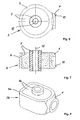
- the bearing eyes 3 are each made up of a sleeve 4 having a tubular extension 6 an aluminum alloy and a vulcanized into the sleeve 4 Rubber-metal element 5 together (see also Figures 6 and 7).
- the aluminum alloy used to manufacture the connecting pipe 2 and the sleeves 4 is expressed in percentages by weight as follows: Si 0.69, Mn 0.33, Mg 0.26, Fe 0.20, remainder A1 as well as melting-related ones Impurities.
- a pipe string is used on the one hand extruded from the aluminum alloy described above and then divided into the length L of a connecting pipe 2 ( Figure 2).
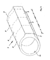
- an extruded profile 7 is made of the aluminum alloy described above, which has the cross-sectional configuration of the sleeves 4 in the raw state. This extruded profile 7 is then then according to the dash-dotted lines in Figure 5 divided into the axial height H of the sleeves 4, so that Shell 8 components result.
- the joints are also in the clamping 13 subjected to a circumferential smoothing by machining or rolling can happen.
- FIG. 3 shows an exploded view of a handlebar 1a with different large configured bearing eyes 3, 3a, but with the axes 12 of the bearing eyes 3, 3a run parallel to each other.
- the connecting pipe 2 corresponds that of Figures 1 and 2.
- the production and joining is like made in the embodiment of Figures 1 and 2.
- FIG. 4 shows an embodiment of a link 1b in an exploded view illustrates in which the axes 12 bearing eyes 3 of the same size are rotated by 90 ° to each other.
- the connecting pipe 2 also corresponds that of Figures 1 and 2, so that the manufacture and joining as is done in the embodiment of Figures 1 and 2.
- a bearing eye 3b is illustrated in a perspective view in FIG. this in contrast to the bearing eyes 3, 3a of Figures 1 to 4, 6 and 7 is oval or approximately rectangular.
- the advantage is any To be able to produce cross sections in the profile and then to vulcanize. Various rubber stiffnesses can be generated with this.
- the Sleeve raw component of this bearing eye 3b is also by a corresponding configured extruded profile and then with a rubber-metal element 5a provided by vulcanization. Then the others follow Manufacturing steps as described above, so that sleeves 4a with Pipe lugs 6 arise. A further explanation is therefore unnecessary.
Landscapes
- Engineering & Computer Science (AREA)
- General Engineering & Computer Science (AREA)
- Mechanical Engineering (AREA)
- Manufacturing & Machinery (AREA)
- Pressure Welding/Diffusion-Bonding (AREA)
- Vehicle Body Suspensions (AREA)
Abstract
Description
- Figur 1
- in der Perspektive einen Lenker für ein Fahrwerk eines Kraftfahrzeugs;
- Figur 2
- den Lenker der Figur 1 in Explosionsdarstellung;
- Figur 3
- den Lenker der Figur 1 in Explosionsdarstellung gemäß einer weiteren Ausführungsform;
- Figur 4
- den Lenker gemäß Figur 1 in Explosionsdarstellung gemäß einer dritten Ausführungsform;
- Figur 5
- ein Strangpressprofil zur Herstellung von Hülsen in der Perspektive;
- Figur 6
- ein Lagerauge des Lenkers der Figur 1 in der Draufsicht;
- Figur 7
- einen vertikalen Längsschnitt durch das Lagerauge der Figur 6 und
- Figur 8
- in der Perspektive ein Lagerauge eines Lenkers gemäß einer weiteren Ausführungsform.
- 1 -
- Lenker
- 1a -
- Lenker
- 1b -
- Lenker
- 2 -
- Verbindungsrohr v. 1, 1a, 1b
- 3 -
- Lageraugen v. 1, 1a, 1b
- 3a -
- Lagerauge
- 3b -
- Lagerauge
- 4 -
- Hülse v. 3, 3a
- 4a -
- Hülse v. 3b
- 5 -
- Gummi-Metall-Element v. 3, 3a
- 5a -
- Gummi-Metall-Element v. 3b
- 6 -
- Rohransatz v. 4, 4a
- 7 -
- Strangpressprofil
- 8 -
- Hülsenrohbauteile
- 9 -
- stutzenartige Ansätze v. 8
- 10 -
- Stirnflächen v. 6
- 11 -
- Stirnseiten v. 2
- 12 -
- Achsen v. 5
- 13 -
- Fügestellen
- 14 -
- Bohrungen in 8
- A -
- Abstand
- L -
- Länge v. 2 plus Aufmaß
Claims (5)
- Verfahren zur Herstellung eines Lenkers (1, 1a, 1b), insbesondere für ein Fahrwerk eines Kraftfahrzeugs, der zwei an die Enden eines Verbindungsrohrs (2) angesetzte Lageraugen (3, 3a, 3b) umfasst, welche jeweils aus einer Hülse (4, 4a) mit stutzenartigem Ansatz (6, 9) und einem in die Hülsen (4, 4a) eingebetteten Lagerelement (5) bestehen, dadurch gekennzeichnet, dass zunächst einerseits ein Rohrstrang mit kreisrundem Querschnitt auf die Länge plus Aufmaß (L) eines Verbindungsrohrs (2) abgeteilt und andererseits ein Strang- oder Fließpressprofil (7) mit der Querschnittskonfiguration der Hülsen (4, 4a) gefertigt und anschließend auf die axiale Höhe (H) der Hülsen (4, 4a) abgeteilt werden, worauf die Lagerelemente (5) in Gestalt von Gummi-Metall-Elementen in die abgeteilten Hülsenrohbauteile (8) einvulkanisiert und danach sowohl die Hülsenrohbauteile (8) als auch das Verbindungsrohr (2) in einer Reibschweißmaschine axial verlagerbar eingespannt werden, wobei in dieser Einspannung zunächst aus den stutzenartigen Ansätzen (9) an den Hülsenrohbauteilen (8) Rohransätze (6) spanend gefertigt und die Rohransätze (6) dann über ihre kreisringförmigen Stirnflächen (10) durch Reibschweißen mit den kreisringförmigen Stirnseiten (11) des Verbindungsrohrs (2) gefügt werden, und dass in dieser Einspannung nach dem kalibrierenden axialen Kaltstauchen der gefügten Bauteile (2, 3, 3a, 3b) die Fügestellen (13) umfangsseitig geglättet werden.
- Verfahren zur Herstellung eines Lenkers (1, 1a, 1b), insbesondere für ein Fahrwerk eines Kraftfahrzeugs, der zwei an die Enden eines Verbindungsrohrs (2) angesetzte Lageraugen (3, 3a, 3b) umfasst, welche jeweils aus einer Hülse (4, 4a) mit einem stutzenartigen Ansatz (6, 9) und einem in die Hülse (4, 4a) eingebetteten Lagerelement (5) bestehen, dadurch gekennzeichnet, dass zunächst einerseits ein Rohrstrang mit kreisrundem Querschnitt auf die Länge (L) plus Aufmaß eines Verbindungsrohrs (2) abgeteilt und andererseits ein Strang- oder Fließpressprofil (7) mit der Querschnittskonfiguration der Hülsen (4, 4a) gefertigt und anschließend auf die axiale Höhe (H) der Hülsen (4, 4a) abgeteilt werden, worauf aus den stutzenförmigen Ansätzen (9) der abgeteilten Hülsenrohbauteile (8) Rohransätze (6) spanend gefertigt und die Lagerelemente (5) in Gestalt von Gummi-Metall-Elementen in die Hülsen (4, 4a) einvulkanisiert werden, und dass dann sowohl die derart gebildeten lageraugen (3, 3a, 3b) als auch das Verbindungsrohr (2) in einer Reibschweißmaschine axial verlagerbar eingespannt und die Rohransätze (6) der Hülsen (4) über ihre kreisringförmigen Stirnflächen (10) durch Reibschweißen mit den kreisringförmigen Stirnseiten (11) des Verbindungsrohrs (2) gefügt werden, wobei in dieser Einspannung nach einem kalibrierenden Kaltstauchen der gefügten Bauteile (2, 3, 3a, 3b) die Fügestellen (13) umfangsseitig geglättet werden.
- Verfahren nach Patentanspruch 1 oder 2, dadurch gekennzeichnet, dass bei dem Rohrstrang und/oder dem Strang-/Fließpressprofil (7) eine Aluminiumlegierung zur Anwendung gelangt, die, in Gewichtsprozenten ausgedrückt, wie folgt zusammengesetzt ist:
Si 0,59 - 0,81 Mn 0,28-0,38 Mg 0,22-0,30 Fe 0,16-0,22 - Verfahren nach einem der Patentansprüch 1 bis 3, dadurch gekennzeichnet, dass bei dem Rohrstrang und/oder dem Strang-/Fließpressprofil (7) eine Aluminiumlegierung zur Anwendung gelangt, die, in Gewichtsprozenten ausgedrückt, wir folgt zusammengesetzt ist:
Si 0,69 Mn 0,33 Mg 0,26 Fe 0,20 - Lenker, insbesondere für das Fahrwerk eines Kraftfahrzeugs, gefertigt nach einem der Patentansprüche 1 bis 4, dadurch gekennzeichnet, dass an die kreisringförmigen Stirnseiten (11) eines insbesondere aus einer Aluminiumlegierung stranggepressten Verbindungsrohrs (2) die kreisringförmigen Stirnflächen (10) von Rohransätzen (6) an mit einvulkanisierten Gummi-Metall-Elementen (5) versehenen Hülsen (4, 4a) aus insbesondere einer Aluminiumlegierung als Bestandteile von Lageraugen (3, 3a, 3b) durch Reibschweißen gefügt sind.
Applications Claiming Priority (4)
| Application Number | Priority Date | Filing Date | Title |
|---|---|---|---|
| DE10159524 | 2001-12-05 | ||
| DE10159524 | 2001-12-05 | ||
| DE10255049A DE10255049B4 (de) | 2001-12-05 | 2002-11-26 | Verfahren zur Herstellung eines Lenkers und Lenker |
| DE10255049 | 2002-11-26 |
Publications (3)
| Publication Number | Publication Date |
|---|---|
| EP1318035A2 true EP1318035A2 (de) | 2003-06-11 |
| EP1318035A3 EP1318035A3 (de) | 2003-09-17 |
| EP1318035B1 EP1318035B1 (de) | 2008-06-18 |
Family
ID=26010710
Family Applications (1)
| Application Number | Title | Priority Date | Filing Date |
|---|---|---|---|
| EP02027027A Expired - Lifetime EP1318035B1 (de) | 2001-12-05 | 2002-12-03 | Verfahren zur Herstellung eines Lenkers und Lenker |
Country Status (3)
| Country | Link |
|---|---|
| US (1) | US6913273B2 (de) |
| EP (1) | EP1318035B1 (de) |
| DE (1) | DE50212379D1 (de) |
Cited By (5)
| Publication number | Priority date | Publication date | Assignee | Title |
|---|---|---|---|---|
| EP1557301A3 (de) * | 2004-01-22 | 2006-05-24 | MAN Nutzfahrzeuge Aktiengesellschaft | Vierpunktlenker zur Anbindung einer Starrachse an den Rahmen eines Nutzfahrzeuges |
| WO2009106071A1 (de) * | 2008-02-29 | 2009-09-03 | Zf Friedrichshafen Ag | Gelenk- und/oder lagereinheit |
| DE102012006688A1 (de) * | 2012-03-31 | 2013-03-14 | Audi Ag | Lenker einer Radaufhängung für ein Fahrzeug |
| DE102012205180A1 (de) * | 2012-03-30 | 2013-10-02 | Zf Friedrichshafen Ag | Lenkerelement für ein Kraftfahrzeug |
| US10124640B2 (en) | 2014-10-09 | 2018-11-13 | Ford Global Technologies, Llc | Vehicle suspension member |
Families Citing this family (18)
| Publication number | Priority date | Publication date | Assignee | Title |
|---|---|---|---|---|
| BR0200820B8 (pt) * | 2002-02-27 | 2013-02-19 | tirante de ligaÇço em compàsito. | |
| DE112006002159T5 (de) * | 2005-08-17 | 2008-10-23 | F. Tech Incorporation | Fahrzeug-Aufhängungslenker |
| DE102006030099B4 (de) * | 2006-06-28 | 2008-10-16 | Zf Friedrichshafen Ag | Kunststoffpendelstütze |
| DE102009009392A1 (de) * | 2009-02-18 | 2010-08-26 | Benteler Automobiltechnik Gmbh | Koppelstange aus Metall |
| DE102009018827A1 (de) * | 2009-04-24 | 2010-10-28 | Neumayer Tekfor Holding Gmbh | Pleuel und Herstellung eines Pleuels |
| DE102009049966A1 (de) * | 2009-10-19 | 2011-04-21 | Benteler Automobiltechnik Gmbh | Verfahren zur Herstellung eines Lenkers |
| KR20110063164A (ko) * | 2009-12-04 | 2011-06-10 | 현대자동차주식회사 | 서스펜션 암 |
| KR101180942B1 (ko) * | 2009-12-04 | 2012-09-07 | 현대자동차주식회사 | 서스펜션 암 |
| DE102010013518A1 (de) * | 2010-03-31 | 2011-10-06 | Trw Automotive Gmbh | Verbindungsstrebe |
| US20120001397A1 (en) * | 2010-07-01 | 2012-01-05 | The Pullman Company | Extruded torque rods |
| DE102012216822A1 (de) * | 2012-09-19 | 2014-05-28 | Bayerische Motoren Werke Aktiengesellschaft | Fahrzeug-Radaufhängung der Schwertlenker-Bauart |
| US8777245B2 (en) | 2012-11-16 | 2014-07-15 | The Pullman Company | Optimized wall thickness torque rod |
| EP2857234B1 (de) * | 2013-10-01 | 2016-07-13 | Gonzalo Florencio Calvo Calleja | Verbindungsglied für einen Stabilisatorstab |
| DE102014101429A1 (de) | 2014-02-05 | 2015-08-06 | Benteler Automobiltechnik Gmbh | Blattfederanbindung |
| DE102014220444A1 (de) | 2014-10-09 | 2016-04-14 | Ford Global Technologies, Llc | Lenker für die Anbindung eines Fahrzeugrads an ein Fahrzeug sowie Fahrzeugradaufhängung |
| DE202014105548U1 (de) | 2014-10-09 | 2015-01-09 | Ford Global Technologies, Llc | Lenker für die Anbindung eines Fahrzeugrads an ein Fahrzeug sowie Fahrzeugradaufhängung |
| JP7102761B2 (ja) * | 2018-02-09 | 2022-07-20 | トヨタ自動車株式会社 | アーム部材の製造方法 |
| DE102018126732A1 (de) * | 2018-10-26 | 2020-04-30 | Dr. Ing. H.C. F. Porsche Aktiengesellschaft | Lenker für ein Lenkersystem zur Anbindung eines Radträgers an eine Karosserie eines Fahrzeugs |
Citations (1)
| Publication number | Priority date | Publication date | Assignee | Title |
|---|---|---|---|---|
| DE19911121A1 (de) | 1998-03-13 | 1999-09-16 | Tokai Rubber Ind Ltd | Lenkerarm, insbesondere für ein Kraftfahrzeug |
Family Cites Families (7)
| Publication number | Priority date | Publication date | Assignee | Title |
|---|---|---|---|---|
| SE502828C2 (sv) * | 1994-05-27 | 1996-01-22 | Scania Cv Ab | Ledanordning vid reaktionsstag |
| JP3114576B2 (ja) * | 1995-06-28 | 2000-12-04 | 日本軽金属株式会社 | トルクロッド及びその製造方法 |
| JPH0986128A (ja) * | 1995-09-27 | 1997-03-31 | Nissan Motor Co Ltd | リンク |
| JP2000142051A (ja) * | 1998-11-05 | 2000-05-23 | Tokai Rubber Ind Ltd | サスペンションアーム |
| JP2000337416A (ja) * | 1999-06-01 | 2000-12-05 | Toyo Tire & Rubber Co Ltd | 防振装置およびその製造方法 |
| JP2001293582A (ja) * | 2000-04-13 | 2001-10-23 | Nissan Motor Co Ltd | アルミニウム製リンク |
| BR0200820B8 (pt) * | 2002-02-27 | 2013-02-19 | tirante de ligaÇço em compàsito. |
-
2002
- 2002-12-03 DE DE50212379T patent/DE50212379D1/de not_active Expired - Lifetime
- 2002-12-03 EP EP02027027A patent/EP1318035B1/de not_active Expired - Lifetime
- 2002-12-05 US US10/310,654 patent/US6913273B2/en not_active Expired - Fee Related
Patent Citations (1)
| Publication number | Priority date | Publication date | Assignee | Title |
|---|---|---|---|---|
| DE19911121A1 (de) | 1998-03-13 | 1999-09-16 | Tokai Rubber Ind Ltd | Lenkerarm, insbesondere für ein Kraftfahrzeug |
Cited By (5)
| Publication number | Priority date | Publication date | Assignee | Title |
|---|---|---|---|---|
| EP1557301A3 (de) * | 2004-01-22 | 2006-05-24 | MAN Nutzfahrzeuge Aktiengesellschaft | Vierpunktlenker zur Anbindung einer Starrachse an den Rahmen eines Nutzfahrzeuges |
| WO2009106071A1 (de) * | 2008-02-29 | 2009-09-03 | Zf Friedrichshafen Ag | Gelenk- und/oder lagereinheit |
| DE102012205180A1 (de) * | 2012-03-30 | 2013-10-02 | Zf Friedrichshafen Ag | Lenkerelement für ein Kraftfahrzeug |
| DE102012006688A1 (de) * | 2012-03-31 | 2013-03-14 | Audi Ag | Lenker einer Radaufhängung für ein Fahrzeug |
| US10124640B2 (en) | 2014-10-09 | 2018-11-13 | Ford Global Technologies, Llc | Vehicle suspension member |
Also Published As
| Publication number | Publication date |
|---|---|
| US6913273B2 (en) | 2005-07-05 |
| EP1318035B1 (de) | 2008-06-18 |
| DE50212379D1 (de) | 2008-07-31 |
| EP1318035A3 (de) | 2003-09-17 |
| US20030122339A1 (en) | 2003-07-03 |
Similar Documents
| Publication | Publication Date | Title |
|---|---|---|
| EP1318035B1 (de) | Verfahren zur Herstellung eines Lenkers und Lenker | |
| DE10258986B4 (de) | Elastisches Fahrwerklager für Nutzfahrzeuge | |
| DE69527376T2 (de) | Rahmenanordnung | |
| DE19930444C2 (de) | Stabilisatoranordnung für ein Kraftfahrzeug | |
| DE19911121A1 (de) | Lenkerarm, insbesondere für ein Kraftfahrzeug | |
| DE60108021T2 (de) | Vibrationsdämpfende Buchse | |
| DE102005043234A1 (de) | Elastomeres Buchsenlager und Verfahren zur Herstellung | |
| DE102013108065B4 (de) | Elastomerlager | |
| DE19953156A1 (de) | Querlenker | |
| DE102010035766A1 (de) | Verfahren und Befestigungsanordnung zum lagerichtigen Befestigen eines Geräts an einem Stukturteil eines Kraftfahrzeugs | |
| EP2674309B1 (de) | Verbundlenkerachse mit Verstärkungsblech | |
| DE10255049B4 (de) | Verfahren zur Herstellung eines Lenkers und Lenker | |
| DE102004057429B4 (de) | Verfahren zum Herstellen von geteilten Rohrstabilisatoren mit Schwenkmotor und geteilter Rohrstabilisator mit Schwenkmotor | |
| DE102016121756B3 (de) | Karosserieanbindung eines Achshilfsrahmens sowie Verfahren zur Herstellung der Karosserieanbindung | |
| DE29704863U1 (de) | Achsschwinge | |
| DE102017010860A1 (de) | Verbindungseinrichtung für die Anbindung einer Dämpfungseinheit eines Fahrzeugs innerhalb einer Radaufhängung des Fahrzeugs | |
| WO2020083589A1 (de) | Innenteil für ein molekulargelenk eines fahrwerklenkers | |
| EP3972777B1 (de) | Verfahren zur herstellung und bearbeitung eines zylinderförmigen hohlkörpers aus aluminium oder einer aluminiumlegierung sowie zu dessen anordnung in einem kraftfahrzeuggetriebe. | |
| DE19954870B4 (de) | Verfahren zum Herstellen einer zylindrischen elastischen Halterung durch ein Einfügen eines elastischen Körpers in ein Aussenhülsenelement und ein Ziehen des letztgenannten, um den elastischen Körper zusammenzudrücken | |
| DE102019107713B4 (de) | Fahrwerkbauteil und Verfahren zur Herstellung eines Fahrwerkbauteils | |
| DE10344951B4 (de) | Gelenkauge für ein Kolben-Zylinderaggregat | |
| DE102018220081A1 (de) | Untergestell-montagestruktur | |
| DE102016123256B4 (de) | Querlenker sowie Verfahren zur Herstellung eines Querlenkers | |
| DE19936540A1 (de) | Stabilisatoranordnung für ein Kraftfahrzeug | |
| DE102018118340B4 (de) | Nutzfahrzeugachsaufhängung |
Legal Events
| Date | Code | Title | Description |
|---|---|---|---|
| PUAI | Public reference made under article 153(3) epc to a published international application that has entered the european phase |
Free format text: ORIGINAL CODE: 0009012 |
|
| AK | Designated contracting states |
Designated state(s): AT BE BG CH CY CZ DE DK EE ES FI FR GB GR IE IT LI LU MC NL PT SE SI SK TR |
|
| AX | Request for extension of the european patent |
Extension state: AL LT LV MK RO |
|
| PUAL | Search report despatched |
Free format text: ORIGINAL CODE: 0009013 |
|
| AK | Designated contracting states |
Kind code of ref document: A3 Designated state(s): AT BE BG CH CY CZ DE DK EE ES FI FR GB GR IE IT LI LU MC NL PT SE SI SK TR |
|
| AX | Request for extension of the european patent |
Extension state: AL LT LV MK RO |
|
| 17P | Request for examination filed |
Effective date: 20030819 |
|
| AKX | Designation fees paid |
Designated state(s): CZ DE FR IT |
|
| GRAP | Despatch of communication of intention to grant a patent |
Free format text: ORIGINAL CODE: EPIDOSNIGR1 |
|
| GRAS | Grant fee paid |
Free format text: ORIGINAL CODE: EPIDOSNIGR3 |
|
| RAP1 | Party data changed (applicant data changed or rights of an application transferred) |
Owner name: BENTELER AUTOMOBILTECHNIK GMBH |
|
| GRAA | (expected) grant |
Free format text: ORIGINAL CODE: 0009210 |
|
| AK | Designated contracting states |
Kind code of ref document: B1 Designated state(s): CZ DE FR IT |
|
| REF | Corresponds to: |
Ref document number: 50212379 Country of ref document: DE Date of ref document: 20080731 Kind code of ref document: P |
|
| PLBE | No opposition filed within time limit |
Free format text: ORIGINAL CODE: 0009261 |
|
| STAA | Information on the status of an ep patent application or granted ep patent |
Free format text: STATUS: NO OPPOSITION FILED WITHIN TIME LIMIT |
|
| 26N | No opposition filed |
Effective date: 20090319 |
|
| PGFP | Annual fee paid to national office [announced via postgrant information from national office to epo] |
Ref country code: DE Payment date: 20131218 Year of fee payment: 12 Ref country code: CZ Payment date: 20131127 Year of fee payment: 12 |
|
| PGFP | Annual fee paid to national office [announced via postgrant information from national office to epo] |
Ref country code: IT Payment date: 20131217 Year of fee payment: 12 |
|
| PGFP | Annual fee paid to national office [announced via postgrant information from national office to epo] |
Ref country code: FR Payment date: 20131220 Year of fee payment: 12 |
|
| REG | Reference to a national code |
Ref country code: DE Ref legal event code: R119 Ref document number: 50212379 Country of ref document: DE |
|
| PG25 | Lapsed in a contracting state [announced via postgrant information from national office to epo] |
Ref country code: CZ Free format text: LAPSE BECAUSE OF NON-PAYMENT OF DUE FEES Effective date: 20141203 |
|
| REG | Reference to a national code |
Ref country code: FR Ref legal event code: ST Effective date: 20150831 |
|
| PG25 | Lapsed in a contracting state [announced via postgrant information from national office to epo] |
Ref country code: DE Free format text: LAPSE BECAUSE OF NON-PAYMENT OF DUE FEES Effective date: 20150701 |
|
| PG25 | Lapsed in a contracting state [announced via postgrant information from national office to epo] |
Ref country code: FR Free format text: LAPSE BECAUSE OF NON-PAYMENT OF DUE FEES Effective date: 20141231 |
|
| PG25 | Lapsed in a contracting state [announced via postgrant information from national office to epo] |
Ref country code: IT Free format text: LAPSE BECAUSE OF NON-PAYMENT OF DUE FEES Effective date: 20141203 |