EP1317902A1 - Vorrichtung zur Beobachtung biologischer Daten - Google Patents
Vorrichtung zur Beobachtung biologischer Daten Download PDFInfo
- Publication number
- EP1317902A1 EP1317902A1 EP02027552A EP02027552A EP1317902A1 EP 1317902 A1 EP1317902 A1 EP 1317902A1 EP 02027552 A EP02027552 A EP 02027552A EP 02027552 A EP02027552 A EP 02027552A EP 1317902 A1 EP1317902 A1 EP 1317902A1
- Authority
- EP
- European Patent Office
- Prior art keywords
- data
- pulse wave
- subject
- value
- blood
- Prior art date
- Legal status (The legal status is an assumption and is not a legal conclusion. Google has not performed a legal analysis and makes no representation as to the accuracy of the status listed.)
- Granted
Links
- 230000036772 blood pressure Effects 0.000 claims abstract description 136
- 238000006243 chemical reaction Methods 0.000 claims abstract description 65
- 210000004204 blood vessel Anatomy 0.000 claims abstract description 44
- 238000004364 calculation method Methods 0.000 claims abstract description 18
- 238000005259 measurement Methods 0.000 claims description 68
- 210000004243 sweat Anatomy 0.000 claims description 53
- 239000008280 blood Substances 0.000 claims description 45
- 210000004369 blood Anatomy 0.000 claims description 45
- 230000017531 blood circulation Effects 0.000 claims description 38
- 230000003444 anaesthetic effect Effects 0.000 claims description 36
- 239000002131 composite material Substances 0.000 claims description 35
- 206010002091 Anaesthesia Diseases 0.000 claims description 27
- 230000037005 anaesthesia Effects 0.000 claims description 27
- 230000007704 transition Effects 0.000 claims description 23
- 238000000034 method Methods 0.000 claims description 20
- QVGXLLKOCUKJST-UHFFFAOYSA-N atomic oxygen Chemical compound [O] QVGXLLKOCUKJST-UHFFFAOYSA-N 0.000 claims description 19
- 239000001301 oxygen Substances 0.000 claims description 19
- 229910052760 oxygen Inorganic materials 0.000 claims description 19
- 210000004556 brain Anatomy 0.000 claims description 8
- 230000002596 correlated effect Effects 0.000 claims description 7
- 230000001678 irradiating effect Effects 0.000 claims description 4
- 230000000747 cardiac effect Effects 0.000 claims description 3
- 239000007788 liquid Substances 0.000 claims description 3
- 238000005070 sampling Methods 0.000 claims description 3
- 238000013500 data storage Methods 0.000 claims 3
- 235000019577 caloric intake Nutrition 0.000 claims 1
- 230000002194 synthesizing effect Effects 0.000 claims 1
- 230000002123 temporal effect Effects 0.000 claims 1
- 238000012545 processing Methods 0.000 description 42
- 230000010349 pulsation Effects 0.000 description 13
- 210000000707 wrist Anatomy 0.000 description 10
- 238000010586 diagram Methods 0.000 description 6
- 238000006073 displacement reaction Methods 0.000 description 6
- 238000002474 experimental method Methods 0.000 description 6
- 239000002775 capsule Substances 0.000 description 5
- 230000035487 diastolic blood pressure Effects 0.000 description 5
- 230000035488 systolic blood pressure Effects 0.000 description 5
- 230000002159 abnormal effect Effects 0.000 description 4
- 210000001367 artery Anatomy 0.000 description 4
- 238000001514 detection method Methods 0.000 description 4
- 238000006467 substitution reaction Methods 0.000 description 4
- 206010003210 Arteriosclerosis Diseases 0.000 description 3
- 241001465754 Metazoa Species 0.000 description 3
- 208000011775 arteriosclerosis disease Diseases 0.000 description 3
- 230000000875 corresponding effect Effects 0.000 description 3
- 230000001172 regenerating effect Effects 0.000 description 3
- 208000024891 symptom Diseases 0.000 description 3
- 108010054147 Hemoglobins Proteins 0.000 description 2
- 102000001554 Hemoglobins Human genes 0.000 description 2
- 238000013208 measuring procedure Methods 0.000 description 2
- 210000003625 skull Anatomy 0.000 description 2
- INGWEZCOABYORO-UHFFFAOYSA-N 2-(furan-2-yl)-7-methyl-1h-1,8-naphthyridin-4-one Chemical compound N=1C2=NC(C)=CC=C2C(O)=CC=1C1=CC=CO1 INGWEZCOABYORO-UHFFFAOYSA-N 0.000 description 1
- GNFTZDOKVXKIBK-UHFFFAOYSA-N 3-(2-methoxyethoxy)benzohydrazide Chemical compound COCCOC1=CC=CC(C(=O)NN)=C1 GNFTZDOKVXKIBK-UHFFFAOYSA-N 0.000 description 1
- IJGRMHOSHXDMSA-UHFFFAOYSA-N Atomic nitrogen Chemical compound N#N IJGRMHOSHXDMSA-UHFFFAOYSA-N 0.000 description 1
- 108010064719 Oxyhemoglobins Proteins 0.000 description 1
- YTAHJIFKAKIKAV-XNMGPUDCSA-N [(1R)-3-morpholin-4-yl-1-phenylpropyl] N-[(3S)-2-oxo-5-phenyl-1,3-dihydro-1,4-benzodiazepin-3-yl]carbamate Chemical compound O=C1[C@H](N=C(C2=C(N1)C=CC=C2)C1=CC=CC=C1)NC(O[C@H](CCN1CCOCC1)C1=CC=CC=C1)=O YTAHJIFKAKIKAV-XNMGPUDCSA-N 0.000 description 1
- 235000019402 calcium peroxide Nutrition 0.000 description 1
- 230000008602 contraction Effects 0.000 description 1
- 238000007796 conventional method Methods 0.000 description 1
- 238000012937 correction Methods 0.000 description 1
- 238000007405 data analysis Methods 0.000 description 1
- 108010002255 deoxyhemoglobin Proteins 0.000 description 1
- 238000003745 diagnosis Methods 0.000 description 1
- 229910001873 dinitrogen Inorganic materials 0.000 description 1
- 230000009977 dual effect Effects 0.000 description 1
- 230000000694 effects Effects 0.000 description 1
- 239000000203 mixture Substances 0.000 description 1
- 230000036407 pain Effects 0.000 description 1
- 210000002321 radial artery Anatomy 0.000 description 1
- 230000006641 stabilisation Effects 0.000 description 1
- 238000011105 stabilization Methods 0.000 description 1
Images


Classifications
-
- A—HUMAN NECESSITIES
- A61—MEDICAL OR VETERINARY SCIENCE; HYGIENE
- A61B—DIAGNOSIS; SURGERY; IDENTIFICATION
- A61B5/00—Measuring for diagnostic purposes; Identification of persons
- A61B5/02—Detecting, measuring or recording for evaluating the cardiovascular system, e.g. pulse, heart rate, blood pressure or blood flow
- A61B5/026—Measuring blood flow
- A61B5/0285—Measuring or recording phase velocity of blood waves
-
- A—HUMAN NECESSITIES
- A61—MEDICAL OR VETERINARY SCIENCE; HYGIENE
- A61B—DIAGNOSIS; SURGERY; IDENTIFICATION
- A61B5/00—Measuring for diagnostic purposes; Identification of persons
- A61B5/02—Detecting, measuring or recording for evaluating the cardiovascular system, e.g. pulse, heart rate, blood pressure or blood flow
- A61B5/021—Measuring pressure in heart or blood vessels
- A61B5/02108—Measuring pressure in heart or blood vessels from analysis of pulse wave characteristics
-
- A—HUMAN NECESSITIES
- A61—MEDICAL OR VETERINARY SCIENCE; HYGIENE
- A61B—DIAGNOSIS; SURGERY; IDENTIFICATION
- A61B5/00—Measuring for diagnostic purposes; Identification of persons
- A61B5/42—Detecting, measuring or recording for evaluating the gastrointestinal, the endocrine or the exocrine systems
- A61B5/4261—Evaluating exocrine secretion production
- A61B5/4266—Evaluating exocrine secretion production sweat secretion
-
- A—HUMAN NECESSITIES
- A61—MEDICAL OR VETERINARY SCIENCE; HYGIENE
- A61B—DIAGNOSIS; SURGERY; IDENTIFICATION
- A61B5/00—Measuring for diagnostic purposes; Identification of persons
- A61B5/48—Other medical applications
- A61B5/4821—Determining level or depth of anaesthesia
Definitions
- This invention relates to a biological data measuring apparatus which measures biological data such as blood pressure, pulses, etc.
- a cuff is used to measure a blood pressure value of a subject at an initial stage of measurement and thereafter, a blood pressure value is calculated on the basis of transition of a photoelectric volume pulse wave obtained from a photoelectric sensor.
- both the cuff and the photoelectric sensor are commonly used at the initial stage of the measurement.
- Calibration is carried out to correlate each one of a photoelectric pulse wave (relative value) and a pressure pulse wave (absolute value) with the other. Once the calibration is carried out, a blood pressure value of the subject can subsequently be calculated only from the measurement by the photoelectric sensor without measurement by the cuff.
- an object of the present invention is to provide a biological data observation apparatus which can calculate a blood pressure value without the preparatory measurement with the cuff.
- the present invention provides a biological data observation apparatus comprising a measuring unit including at least a photoelectric sensor including a light emitting element for emitting light with a predetermined wavelength onto a blood vessel of a subject and a light detecting element for detecting, as a photoelectric volume pulse wave, a change in an amount of transmitted or reflected light resulting from the light emitted from the light emitting element, an operational unit into which a result of measurement by the measuring unit is supplied so that the operational unit carries out an operational process based on the supplied result of measurement, a storage area storing data of the result of measurement or the like, and a display unit displaying a result of calculation performed by the operational unit, characterized in that the storage area stores blood pressure conversion data correlating a pulse wave area and a blood pressure value in order that a pulse wave area may be converted to a blood pressure value as an absolute value, the pulse wave area being obtained by integrating a waveform of the photoelectric volume pulse wave per heartbeat, an the operational unit calculates the pulse wave area on the basis of the photo
- the storage area stores the blood pressure conversion data in which the pulse-wave area of the photoelectric volume pulse-wave and blood pressure value are correlated with each other. Accordingly, when a photoelectric volume pulse wave of the subject is measured by the photoelectric sensor, a blood pressure value of the subject is obtained from the pulse wave area of the photoelectric volume pulse wave and the blood pressure conversion data. Consequently, the above-described apparatus can eliminate the measurement of pressure pulse wave by a cuff in the initial stage of measurement and resultant calibration, whereupon the measuring procedure can be simplified.
- the biological data observation apparatus comprises a pulse-wave measuring device 20, a data processing device 10 connected to an output line of the pulse-wave measuring device 20 to carry out operational processing, and a monitor 30 (serving as a display unit in the invention) displaying results of operational processing by the data processing device 10.
- the pulse-wave measuring device 20 includes a photoelectric sensor 6 (serving as a measuring unit in the invention) irradiating light with a predetermined wavelength onto a blood vessel of a subject 5 thereby to detect, as a photoelectric volume pulse wave, a change in amount of resultant transmitted or reflected light.
- the data processing device 10 includes an A/D converter 11, a CPU 12 (serving as an operational unit in the invention) and a storage area 13.
- the photoelectric volume pulse wave detected by the pulse wave measuring device 20 is continuously supplied via an A/D converter 11 into the CPU 12.
- the CPU 12 carries out operational processing on the basis of the digitized photoelectric volume pulse wave data, blood pressure conversion data written in the storage area 13, flow velocity conversion data, etc., thereby calculating a blood pressure value of the subject per heartbeat.
- the monitor 30 displays a blood pressure waveform and photoelectric volume pulse wave each in the unit of heartbeat.
- the pulse-wave measuring device 20 comprises a wrist band 21 and a body 22.
- the wrist band 21 has both ends adapted to be joined with each other so that the pulse-wave measuring device 20 is fixed around a wrist of the subject 5.
- the body 22 includes a casing 23 having an open side applied onto an arm of the subject 5 and a plate 24 closing the open side.
- the plate 24 is elastically supported by a coil spring 25 disposed between the casing 23 and the plate, so that the plate is usually pressed against a skin of the subject 5.
- the plate 24 has a plurality of through holes into which a plurality of light emitting elements 26A and light detecting elements 26B are inserted from inside the casing 23 to be fixed.
- the light emitting elements 26A and light detecting elements 26B constitute a photoelectric sensor 26 for detecting a relative change in blood flow of the subject 5 as a change in an amount of light.
- Each light emitting element comprises a light-emitting diode (LED), whereas each light detecting element comprises a phototransistor. Each LED obtains output according to an amount of blood flow from the phototransistor.
- the pulse-wave measuring device 20 includes a drive circuit (not shown) for driving the light emitting elements 26A and a receiving circuit (not shown) for processing an output signal delivered from the light detecting element 26B. Data of an obtained photoelectric volume pulse wave is transmitted via an output line to the data processing device 10.
- a blood pressure value Pt of the subject is calculated mainly by operational processing in the embodiment as will be described later.
- the operational processing requires reference data of a blood pressure value Po and a flow velocity value Vo.
- the storage area 13 stores blood pressure conversion data for calculation of the blood pressure value Po and flow velocity conversion data for calculation of the flow velocity value Vo. Both data are obtained from experiments using a measuring artificial human body model 40 as will be described in detail later.
- the measuring artificial human body model 40 reproduces a rested state of a sampling object with a standard form.
- the model 40 comprises a tank 41 storing an equivalent 49 to human blood (hereinafter, "blood equivalent") , a tube 42 through which the blood equivalent 49 is re-circulated and transferred, and a pump 43 pressure-feeding the blood equivalent 49 for every standard heartbeat time which is one of the sample person at rest, for example, 0.75 sec.
- the blood equivalent preferably has a similar composition as the human blood, and blood of any animal may be used, for example.
- the tube 42 serves as a pipe in the invention and corresponds to a blood vessel.
- the pressure of the pump 43 is adjustable.
- a flow rate sensor 44 is provided in the middle of the tube 42 for measuring a flow rate of the blood equivalent 49 per standard heartbeat time.
- the flow rate sensor 44 serves as a flow rate measuring section in the invention.
- a photoelectric sensor 45 is provided for detecting, as a change in an amount of light, a change in the flow rate of the blood equivalent 49 in the tube.
- a pressure measuring section 46 includes a container 47 partitioned by a rubber pressure valve 47A into upper and lower chambers and a pressure sensor 48 connected to the lower chamber side of the container 47.
- the tube 42 is connected to the upper chamber so that the blood equivalent can be re-circulated therein.
- the tube 42 has an inner diameter approximately equal to one of a blood vessel in a wrist of the sample person in the rested state.
- the inner diameter of the tube 42 is set at ⁇ 2.5 mm in the embodiment.
- the foregoing "rested state" is set because the artificial model 40 reproduces the rested state of the sample person.
- the blood vessel in the wrist is selected because a part of the subject where measurement actually is carried out is a wrist. It is desirable that the photoelectric sensor 26 of the pulse-wave measuring device 20 and the photoelectric sensor 45 of the artificial model 40 should be of the same type.
- the pressure valve 47A is displaced downward upon pressure feed of the blood equivalent 49, whereby the pressure at the lower chamber side is varied to be rendered maximum.
- the pressure corresponding to a systolic blood pressure of the human body at rest is measured by the pressure sensor 48.
- the pressure valve 47A is moved to the upper chamber side after pressure feed of the blood equivalent 49, whereby the pressure at the lower chamber side is varied to be rendered minimum.
- the pressure corresponding to a diastolic blood pressure of the human body at rest is measured by the pressure sensor 48.
- output lines of the photoelectric sensor 45, flow-rate sensor 44, pressure sensor 48 are connected to the A/D converter 11.
- the pressure at which the blood equivalent 49 is pressure-fed by the pump 43 is changed to various values so that the photoelectric volume pulse wave and the pressure value of the blood equivalent 49 are measured by the photoelectric sensor 45 and the pressure sensor 48 every time of setting respectively, whereupon the subsequent blood pressure conversion data and flow rate conversion data are calculated. See FIGS. 4A to 4C.
- a pulse wave area obtained by integrating the photoelectric volume pulse wave regarding the tube 42 per heartbeat and the blood pressure value of the blood equivalent obtained from the pressure sensor 48 are correlated with each other.
- the blood pressure conversion data is calculated at every systolic blood pressure and every diastolic blood pressure. See FIG. 4C.
- the pulse wave area and flow velocity value are correlated with each other in the flow velocity conversion data. See FIG. 4B.
- the flow velocity value is obtained by dividing a flow rate measured by the flow rate sensor 44 by a sectional area of the tube 42.
- a manner of calculating a blood pressure value Pt in any period will be described with reference to FIG. 5.
- a wrist band 21 is fastened around an arm of the subject 5, and the pulse-wave measuring device 20 is set so that the photoelectric sensor 26 is located above a blood vessel of the subject 5.
- a photoelectric volume pulse wave is measured by the sensor 26 while the subject 5 is in a temporally rested state or measurement reference state (measurement reference time).
- the measured photoelectric volume pulse wave is delivered via the A/D converter 11 to CPU 12 (step a).
- a mean value of the inner diameter of the subject's blood vessel takes approximately the same value as the inner diameter of the tube 42 although the inner diameter value of the subject's blood vessel varies to some extent. Consequently, reference blood pressure and flow velocity values Po and Vo can be calculated on the basis of the blood pressure data and flow velocity conversion data respectively.
- both data cannot be used when the subject changes from a rested state to a non-rested state such that the inner diameter of the blood vessel differs from the inner diameter of the tube 42 as the result of expansion and contraction of the blood vessel.
- a pulse wave area per heartbeat is calculated on the basis of the photoelectric volume pulse wave (relative value) of the subject 5.
- the pulse wave area per heartbeat is converted to a value per above-mentioned standard heartbeat time (step b).
- Reference symbol "S" will hereinafter designate the converted pulse wave area s2.
- a flow velocity value (absolute value) in the measurement reference state is calculated from the converted pulse wave area S and flow velocity conversion data as shown in FIG. 4B (step c).
- the flow velocity value is represented by Vo when the converted pulse wave area S is represented by So.
- the blood pressure value (absolute value) of the subject 5 in the measurement reference state is calculated from the converted pulse wave area S and the blood pressure conversion data as shown in FIG. 4C (step c).
- the blood pressure value Po is represented as systolic blood pressure value Pho and diastolic blood pressure value PLo.
- the blood pressure value Pt is thereafter calculated by the following operational processing in a suitable period.
- a blood pressure variation ⁇ P refers to a variation in the blood pressure value in any period relative to the value at a measurement reference time.
- the blood pressure variation ⁇ P is calculated on the basis of the calculated flow velocity value Vt in any period, the flow velocity value Vo at the measurement reference time and the blood pressure value Po at the measurement reference time (step d). More specifically, a relation expressed by the following equation (4) holds between the flow velocity and blood pressure values Vo and Po at the measurement reference time and the flow velocity and blood pressure values Vt and Pt in any period. Equation (5) is obtained from the equation (4).
- the blood pressure variation amount ⁇ P can be calculated on the basis of equation (5).
- the systolic blood pressure value Pho in the measurement reference state is substituted for "Po" in equation (6) in order that a systolic blood pressure Pht per heartbeat in any period may be calculated.
- the diastolic blood pressure value PLo in the measurement reference state is substituted for "Po" in equation (6)(step e).
- the storage area 13 stores the blood pressure conversion data and flow rate conversion data.
- the reference flow velocity and blood pressure values Vo and Po are calculated on both conversion data respectively.
- the blood pressure variation amount ⁇ P which is a variation in the blood pressure value in any period relative to the value at a measurement reference time, can be obtained by operation from the peak values Do and Dt of the photoelectric volume pulse wave and the flow velocity value Vo at the measurement reference time.
- the blood pressure value Pt in any period is calculated on the basis of the obtained blood pressure variation amount ⁇ P.
- the blood pressure value Pt can be obtained by operation whether the subject 5 is in a rested state or not.
- the blood pressure value Pt in any period can be calculated on the basis of only the measurement of the photoelectric volume pulse wave by the photoelectric sensor 26 without measurement of pressure pulse wave by the cuff etc. As a result, the blood pressure measuring procedure can be simplified.
- non-rested state refers to a case where physical conditions of the subject 5 change with course of measurement such that the inner diameter of blood vessel of the subject is contracted or expanded as compared with the rested state.
- the artificial model 40 includes a laser displacement meter 95 built therein as shown in FIG. 3.
- the laser displacement meter 95 irradiates laser beams onto the tube 42. Light reflected on the tube 42 is condensed through a lens onto a light-receiving plane so as to be focused on it.
- the laser displacement meter 95 further measures an amount of displacement of a focal point on the light-receiving surface thereby to measure a variation in the inner diameter of the tube 42. More specifically, although the inner diameter of the tube 42 is ⁇ 2.5 before the experiment, the tube 42 is expanded and contracted with variations in the pressure since the blood equivalent 49 is force-fed through the tube in the experiment.
- the inner diameter of the tube 42 is measured by the laser displacement meter 95 during the experiment, and a mean value of the inner diameter is obtained.
- the blood pressure and flow velocity conversion data measured using the tube 42 are amended or converted so that the data correspond to the inner diameter of ⁇ 2.5.
- the laser displacement meter 95 can be used to verify the blood pressure value obtained in any period (particularly in a non-rested state) from the equation (6). More specifically, the blood vessel is expanded or contracted in the non-rested state as compared with the rested state. For example, consider the case where a mean inner diameter value of the subject's blood vessel is ⁇ 2.5 in the rested state. In this case, when the mean value changes from ⁇ 2.5 to ⁇ 4.0 with the subject's change from the rested state to the non-rested state, a tube 42 having the inner diameter of ⁇ 2.5 is provided in the artificial model 40, and pressure is adjusted by a pump so that the mean value of the tube's inner diameter becomes ⁇ 4.0.
- a flow rate and pressure of the blood equivalent 49 are measured by the flow rate sensor 44 and the pressure sensor 48 respectively.
- the results of measurement are compared with the blood pressure value calculated on the basis of equation (6), whereby whether the blood pressure value is correct can experimentally be verified. Further, a correction factor or the like can be obtained when the blood pressure value calculated on the basis of equation (6) is compared with a blood pressure value actually measured in the experiment.
- the blood pressure and flow velocity conversion data are based on data obtained when the tube has the inner diameter of ⁇ 2.5.
- blood pressure and flow velocity conversion data may be provided so as to correspond to different inner diameters of tubes.
- the storage area 13 may store a plurality of data table, and tubes 42 for the respective sizes of ⁇ 2.0, ⁇ 2.5, ⁇ 3.0, etc. are prepared for the artificial model 40. Measurement is carried out with the tube 42 changed from one to another. The blood pressure data and flow velocity data are calculated for each tube 42 to be written onto the respective data table.
- a blood vessel diameter measuring section serving as a measuring unit may be provided for measuring an inner diameter of blood vessel of the subject 5.
- a data table of tube diameter corresponding to the subject's blood vessel inner diameter is selected on the basis of the results of calculation. See step g in FIG. 6. Consequently, the differences in the bodies of the subjects 5 can be eliminated and accordingly, a more accurate blood pressure value can be obtained.
- the photoelectric sensor 26 may be attached to a finger tip so that light with a predetermined wavelength is irradiated onto a regular pulse in the finger tip.
- the blood vessel diameter measuring section detects the resultant transmitted light.
- output to be obtained corresponds to the variations in the blood vessel diameter when the transmitted light belongs to a wavelength range in which the light is absorbed into a component in the blood vessel such as hemoglobin.
- the inner diameter of the blood vessel can be measured on the basis of the variations in the flow velocity Vt. More specifically, the flow velocity value Vt varies with variations in the inner diameter of the blood vessel. The flow velocity is increased in a part of the blood vessel where the inner diameter thereof is reduced.
- the flow velocity is reduced in a part of the blood vessel where the inner diameter thereof is increased. Accordingly, when the flow velocity is measured at a plurality of parts of a single blood vessel, the inner diameter of the blood vessel can be obtained on the basis of the differences in the flow velocity Vt between the parts.
- the above-described biological data observation apparatus can be used in the following manner.
- the photoelectric sensor 26 is disposed on different parts of a single blood vessel of the subject 5.
- a photoelectric volume pulse wave is measured at each part by the light emitting element 26A and the light detecting element 26B.
- a blood flow rate is then calculated for every measured part by the CPU 12. If the blood vessel is narrowed by arteriosclerosis, the flow rate of blood is reduced to a large degree at the narrowed part of the vessel. Accordingly, arteriosclerosis can be detected when the flow rates of blood calculated by the CPU 12 are compared with one another.
- the flow velocity is firstly calculated on the basis of the photoelectric volume pulse wave and flow velocity conversion data. The obtained flow velocity is multiplied by a sectional area of the blood vessel.
- the wrist band 21 of the pulse-wave measuring device 20 is modified so as to be fastened around the head and is set so that the photoelectric sensor 26 is directed to the skull.
- the irradiated light is transmitted through the skull so that the photoelectric volume pulse wave according to the blood flow rate in the blood vessel can be measured in a noninvasive manner.
- the photoelectric sensor 26 is used to irradiate light onto another artery such as the radial artery or antebrachial artery, a photoelectric volume pulse wave can be measured according to a change in the blood flow rate in the artery.
- the photoelectric sensor 26 constitutes the measuring unit in the foregoing embodiment.
- a second photoelectric sensor 96 is further provided in addition to the photoelectric sensor 26.
- the flow velocity values Vo and Vt of the subject 5 are calculated on the basis of the flow velocity conversion data in the foregoing embodiment.
- the second photoelectric sensor 96 detects a plurality of photoelectric volume pulse waves, and the flow velocity values Vo and Vt are calculated on the basis of a phase difference between the detected photoelectric volume pulse waves.
- the other arrangement in the second embodiment is similar to that in the foregoing embodiment and accordingly, detailed description of the other arrangement will be eliminated.
- the photoelectric sensor 26 serves as a first photoelectric sensor in the invention.
- the second photoelectric sensor 96 is applied around the wrist of the subject 5, for example, and comprises a single light emitting element 97 and a plurality of light detecting elements 98A, 98B and 98C.
- the light detecting elements 98A-98C are disposed at regular intervals L along the blood vessel and simultaneously detect light irradiated by the light emitting element 97 to be reflected (a transmitted light for convenience in explanation in FIG. 8).
- the interval L between the light detecting elements is set at a value ranging from several mm to several tens mm.
- FIGS. 9A to 9C illustrate transition of photoelectric volume pulse waves obtained from the light detecting elements 98A to 98C respectively.
- reference symbols ta, tb and tc designate peak values of the photoelectric volume pulse waves respectively.
- the values Vo and Vt can be obtained when the phase difference between the photoelectric volume pulse waves at the measurement reference time and in any period is substituted for (ta-tb) in equation (7). Additionally, three light detecting elements 98A to 98C are provided in the second embodiment. A flow velocity value between the elements 98A and 98B is obtained, and a flow velocity between the elements 98B and 98C is also obtained. A mean value of both flow velocity values serves as a flow velocity value in the second embodiment.
- the inventors have found that there is a correlation between the flow velocity value Vt and a period of the photoelectric volume pulse wave detected by each of the photoelectric sensors 26 and 96. Accordingly, when turning our attention to the period of the photoelectric volume pulse wave (for example, tw in FIG. 9B), the transition of the flow velocity value can be obtained from the period of the photoelectric volume pulse wave without provision of a plurality of light detecting elements.
- a blood flow rate of the subject 5 can also be calculated on the basis of the blood pressure and flow velocity conversion data, for example.
- a pressure sensor serving as the blood pressure measuring section in the invention is provided as the measuring unit in stead of the photoelectric sensor 26.
- a blood pressure value Po is obtained from the pressure sensor at the measurement reference time and furthermore, a converted pulse wave area and accordingly flow velocity values So and Vo are calculated on the basis of the blood pressure and flow velocity conversion data.
- the value Vt is calculated by substituting values for Pt, Po and Vo in equation (4) respectively.
- ⁇ t is further calculated by substituting values for ⁇ t, Vo and Vt. Consequently, a blood flow rate of the subject 5 in any period can be obtained on the basis of the inner diameter of the blood vessel of the subject 5 and the flow velocity Vt of the blood.
- a body motion sensor 51 serving as the measuring unit is added for detecting a slight motion of the subject 5. Furthermore, a pulse wave regenerating circuit 57 and a body motion detecting section 59 are added to the data processing device 10.
- the body motion detecting section 59 constitutes part of the operational unit in the invention.
- a substituting process which will be described in detail later is carried out on the basis of determination of the waveform data of the photoelectric volume pulse wave and the results of determination.
- the other arrangement in the third embodiment is similar to that in the first embodiment and accordingly, detailed description of the other arrangement will be eliminated.
- the body motion sensor 51 is disposed side by side with the photoelectric sensor 26 and comprises a blue LED (light emitting element) irradiating light with a wavelength of 420 mm, for example and a phototransistor (light detecting element) detecting the light reflected.
- the light emitted from the blue LED is reflected on a skin surface of the subject, and output of the phototransistor is detected as slight body movement of the subject 5.
- the photoelectric sensor 26 is connected via an amplifier 52 to a low-pass filter 53 and a high-pass filter 54 so that output of the sensor 26 is supplied to the data processing device 10.
- the low-pass filter 53 cuts off frequencies at or below 30 Hz in order to eliminate low-frequency components as noise.
- the high-pass filter 54 cuts off high-frequency components or frequencies at or above 150 Hz.
- the body motion sensor 51 is connected via an amplifier 55 to an active filter 56 (bandpass filter).
- the active filer 56 transmits a predetermined band of frequencies to the data processing device 10 while rejecting all other frequencies.
- the data processing device 10 comprises a multiplexer 58, a pulse wave reproducing circuit 57 and a body motion detecting section 59 in addition to the storage area 13, CPU 12 and A/D converter 12.
- An input signal from the photoelectric sensor 26 is supplied via the pulse wave regenerating circuit 57 to the multiplexer 58 and CPU 12.
- An input signal from the body motion sensor 51 is supplied via the body motion detecting section 59 and multiplexer 58 to CPU 12.
- the pulse wave reproducing circuit 57 is connected further to the body motion detecting section 59.
- an output waveform of the body motion sensor 51 is subtracted from an output waveform delivered from the photoelectric sensor 26 to be passed through the filters 53 and 54.
- the pulse wave regenerating circuit 57 generates a waveform in which the body motion components (particularly slight body motion of the subject) have been eliminated from the output of the photoelectric sensor 26.
- the processing carried out by the pulse wave reproducing circuit 57 constitutes a modifying process in the invention.
- Output data of the photoelectric sensor 26 is thus processed through the noise eliminating process by the low-pass and high-pass filters 53 and 54 and the modifying process in which the body motion sensor 51 detects slight body motion of the subject 5 and body motion components are subtracted from the output of the photoelectric sensor 26, whereupon only pure pulse wave components are continuously extracted. Consequently, since error components are eliminated from the photoelectric volume pulse waveform, an accurate photoelectric volume pulse wave can be obtained.
- the determination of the photoelectric volume pulse wave depends upon whether a period of the photoelectric volume pulse wave is within a predetermined allowed range (step j).
- the predetermined allowed range is a normal range of the period of the photoelectric volume pulse wave, for example, a range of 0.75 to 1.5 sec.
- the waveform of the photoelectric volume pulse wave disturbs such that the period thereof is out of the allowed range.
- the data processing device 10 When determining that the period of the photoelectric volume pulse wave is within the allowed range, the data processing device 10 advances to a first blood pressure calculating step (step k), whereas the data processing device 10 advances to a step in which the substitution of the photoelectric volume pulse wave is carried out (step n) when determining that the period of the photoelectric volume pulse signal is out of the allowed range.
- a blood pressure variation amount ⁇ P and a blood pressure value Pt of the subject in the non-rested state are calculated on the calculated basis of the flow velocity value Vo and blood pressure value Po in the rested state, the peak value of the photoelectric volume pulse wave etc.
- the data processing device 10 then collates the obtained blood pressure value Pt with the blood pressure reference value, thereby checking it (step m).
- the blood pressure reference value is a range of blood pressure obtained by a normal measurement (for example, range of 50 to 140 mmHg).
- the data processing device 10 determines that the measurement has normally been carried out, displaying the transition of blood pressure Pt.
- the data processing device 10 determines that measurement is erroneous, returning to the pulse wave measuring step (step a) for re-calculation of the blood pressure value Pt.
- the data processing device 10 executes a substitution processing for the photoelectric volume pulse wave.
- a substitution processing as shown in FIGS. 12A and 12B, a mean waveform model (a hatched portion in FIG. 12B) which will be described later is substituted for abnormal wave form part of the measured photoelectric volume pulse wave or part of waveform data out of the allowed range.
- a blood pressure value is calculated in a second blood pressure value calculating step (step o).
- a flow velocity value Vo and blood pressure value Po in the subject's rested state are calculated, and a blood pressure variation amount ⁇ P is calculated on the basis of a peak value of the photoelectric volume pulse wave etc.
- a blood pressure value Pt in the subject's non-rested state is lastly calculated.
- a blood pressure variation amount ⁇ P and a blood pressure value Pt in the subject's non-rested state are calculated on the basis of the substituted peak value of photoelectric volume pulse wave.
- the data processing device 10 advances to step m to check the blood pressure value.
- the mean waveform model is calculated on the basis of waveform data of the subject 5 within the allowed range. More specifically, waveform data of photoelectric volume pulse wave is supplied into the storage area 13 at any time after start of measurement. On the other hand, CPU 12 calculates a mean value on the basis of a peak value and period etc. regarding the waveform data which has been measured until detection of waveform data which is out of the allowed range. CPU 12 then obtains a mean wave form model based on the results of calculation.
- the data processing device 10 carries out determination of the photoelectric volume pulse wave, error due to such a large body motion that cannot be detected by the body motion sensor 51 can be eliminated and furthermore, an accurate photoelectric volume pulse wave can be obtained. Accordingly, a reliable diagnosis can be made when data analysis (for example, calculation of a mean blood pressure value) is carried out about a blood pressure value after detection of the blood pressure value.
- the photoelectric volume pulse wave is measured at the wrist of the subject 5 (measurement part) in the embodiment.
- an error sometimes occurs in the measurement because a vertical distance between the measurement part and the heart of the subject differs depending upon an angle of the subject' s arm.
- An angular compensation can be made by the CPU 12 when an angle sensor is provided for detecting an angle of the subject's arm as a measure to prevent the foregoing error.
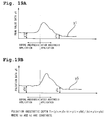
- the data processing device 10 can calculate an oxygen saturation of arterial blood SaO2 as well as the above-described blood pressure value. A calculating procedure will be described with reference to FIG. 13.
- the data processing device 10 calculates a blood flow rate Q on the basis of the blood pressure and flow velocity conversion data and photoelectric volume pulse wave and further calculates a pulsation E on the basis of a period of the photoelectric volume pulse wave.
- the pulse-wave measuring device 20 constitutes the measuring unit and measures mainly a blood pressure in the first embodiment
- the measuring unit comprises a sweat amount measuring device 70 serving as a sweat amount measuring section and a temperature sensor 60 for detecting a skin temperature and serving as skin temperature measuring section, in addition to the pulse-wave measuring device 20.
- a degree of anesthesia which will hereinafter be referred to as "anesthesia depth"
- anesthesia depth is calculated on the basis of the results of detection by the afore-mentioned devices.
- the other arrangement in the fourth embodiment is similar to that in the first embodiment and accordingly, detailed description of the other arrangement will be eliminated.
- Biological data obtained by each measuring devices will hereinafter be referred to as "primary biological data.”
- the sweat amount measuring device 70 has the same operating principle as a sweat amount measuring device disclosed in JP-A-10-262958 filed by the assignee of the present application. More specifically, the sweat amount measuring device 70 includes a capsule 71 having a recess 72. The capsule 71 is attached to the skin surface of the subject with an opening of the recess 72 being closed by the skin surface. The capsule 71 includes a side formed with a supply opening 73 and a discharge opening 74 both communicating with the recess 72. A low-humidity nitrogen gas reserved in a cylinder (not shown) is supplied at a predetermined flow rate into the recess 72 through a rubber tube 73A communicating with the supply opening 73.
- a humidifier (not shown) is provided in the middle of a rubber tube 74A communicating with the discharge opening 74 for measuring a humidity of air discharged.
- the capsule 71 includes a thermometer and a heater-cooler (for example, Peltier element) both built therein so that an interior of the recess 72 is maintained at a constant temperature.
- the sweat amount measuring device 70 has an output line connected via the A/D converter 11 to the CPU 12 so that output of the humidifier and thermometer is supplied into the data processing device 10.
- the data processing device 10 executes an operation on the basis of the supplied output, obtaining a sweat amount of the subject (sweat amount data).
- the temperature sensor 60 for the detection of skin temperature may be of the thermal expansion type, thermocouple type or thermistor type.
- the temperature sensor 60 is attached to an arm of the subject 5 etc. for measuring purpose, thereby detecting a skin temperature of the subject.
- the temperature sensor 60 also has an output line connected via the A/D converter to the CPU 12. Output of the temperature sensor 60 is supplied into the data processing device 10, which then executes an operation on the basis of the supplied output to obtain a ski temperature of the subject 5 (skin temperature data).
- the data processing device 10 calculates peak value data regarding a peak value and pulsation data on the basis of the photoelectric volume pulse wave obtained from the pulse-wave measuring device 20.
- the data processing device 20 further calculates a flow velocity value on the basis of flow velocity conversion data and further calculates an oxygen saturation of arterial blood (oxygen saturation data) on the basis of the obtained flow velocity value.
- the data processing device 10 calculates an anesthesia depth T based on the obtained primary biological data.
- the data processing device 10 obtains composite data from the primary biological data and calculates an anesthesia depth T based on the obtained composite data.
- peak value data yl serves as reference data.
- y1 is peak value data
- y2 is sweat amount data
- y3 oxygen saturation data
- y4 is skin temperature data
- y5 pulsation data
- h1 to h5 are constants
- F to I are functions.
- the peak value data is selected as the reference data as described above. The reason for this selection is that the peak value data shows a best
- Each of the oxygen saturation data y3, skin temperature data y4 and pulsation data y5 is synthesized into the composite data A2 as in the same manner as described above, whereupon the composite data is calculated. See FIG. 17.
- the anesthetic depth T is thus obtained as an absolute value on the basis of a ratio of the reference value Ao of the composite data A to the value At of composite data after application of anesthesia .
- transition of the calculated anesthesia depth is displayed on the monitor 30 with the composite data A.
- a plurality of primary biological data closely related with a degree of anesthesia are put together into a signal data for the purpose of measuring the anesthesia depth. Accordingly, since a plurality of primary biological data are compensated by one another, a more accurate anesthetic depth T can be obtained as compared with the case where the anesthetic depth is calculated on the basis of a single primary biological data.
- a reference value Ao used for calculation of the anesthetic depth is the one obtained after application of anesthesia.
- any value composing composite data A maybe used.
- a peak value obtained after application of anesthesia may be used.
- an anesthetic depth is calculated for each primary biological data. Thereafter, the anesthetic depth values calculated on the basis of the respective primary biological data are added together, so that a synthetic anesthetic depth is obtained.
- Calculation exemplified here is based on the peak value data y1, sweat amount data y2, oxygen saturation data y3 and pulsation data y5. However, the calculation may be based on only the peak value data y1, sweat amount data y2 and pulsation data y5.
- the CPU 12 calculates a mean value of each primary biological data before application of anesthesia, that is, a mean value y1o of peak value data y1, mean value y2o of sweat amount data y2, mean value y3o of oxygen saturation data y3 and mean value y5o of pulsation data y5.
- a plurality of primary biological data related with an anesthetic depth are put together into a single data in the same manner as described above. Accordingly, since a plurality of primary biological data are compensated with one another, a more accurate anesthetic depth T can be obtained as compared with the case where the anesthetic depth is calculated on the basis of a single primary biological data.
- Transition of the obtained anesthetic depth T is displayed on the monitor 30 (see FIG. 20). While confirming transition of anesthetic depth T on the monitor 30, the doctor adjusts an amount of anesthesia applied to the subject 5. The doctor starts operation when understanding that the anesthetic depth T is stable at a suitable value. On the other hand, in a case where the subject 5 has an abnormal symptom, the doctor learns the abnormal symptom when viewing transition of anesthetic depth on the monitor 30. In this case, when alarming means is provided in the data processing device 10, the doctor can be informed of the abnormal symptom of the subject 5 without depending upon the contents displayed on the monitor 30.
- An electrocardiograph 80 serving as a heartbeat measuring section and an electroencephalograph 90 serving as a brain wave measuring section may be provided in addition to the above-described measuring unit as shown in FIG. 21.
- the electrocardiograph 80 includes electrodes applied to the body surface of the subject 5 for detecting a feeble electric signal generated when the heart beats.
- the electric signal is amplified by an amplifier to be delivered as heart-beat data y6.
- the electroencephalograph 90 has the same operating principle as the electrocardiograph 80 and includes electrodes applied to the head of the subject 5 for detecting a feeble electric signal generated in the brain as the result of working of the brain.
- the signal is amplified by the amplifier to be delivered as brain wave data y7.
- the data processing device 10 calculates the anesthetic depth T based on the seven primary biological data, that is, the peak value data y1, sweat amount data y2, oxygen saturation data y3, skin temperature data y4, pulsation data y5, heart-beat data y6 and brain wave data y7. Further accurate anesthetic depth T can be calculated since the heart beat and brain wave are parameters closely related with the anesthetic depth T.
- a fifth embodiment of the invention will be described with reference to FIGS. 22A and 22B.
- the anesthetic depth T of the subject 5 is calculated in the fourth embodiment, a total calorie of the subject 5 is calculated.
- the biological data observation apparatus includes a temperature sensor 60 serving as the measuring unit and detecting a skin temperature.
- the storage area 13 stores body surface area conversion data which will be described below.
- the body surface area conversion data contains a correlation between a person' s figure and body surface area. For example, a person's body surface area is calculated when data of height, weight, age and sex of the person is entered. Accordingly, when a skin temperature of the subject 5 is measured by the temperature sensor 60 and a mean value of the measured skin temperatures per predetermined time is calculated by the CPU, a total calorie of the subject 5 can be calculated on the basis of the mean skin temperature value and the body surface area.
- the skin temperature of the subject 5 can also be calculated on the basis of the photoelectric volume pulse wave. More specifically, the inventors have found that a skin temperature has a relation with a blood flow rate. Accordingly, a photoelectric volume pulse wave is measured by the pulse wave measuring device 20 so that a peak value of the photoelectric volume pulse wave is obtained. A flow velocity value is calculated on the basis of flow velocity conversion data, and a blood flow rate is calculated. Skin temperature and blood flow conversion data is calculated on the obtained blood flow rate and skin temperature (see FIGS. 22A and 22B.). The skin temperature and the blood flow rate are correlated with each other in the calculated conversion data.
- the skin temperature and blood flow conversion data is written into the storage area 13 for every subject 5.
- the skin temperature of the subject 5 can be calculated on the basis of the skin temperature and blood flow conversion data written in the storage area 13 when the photoelectric volume pulse wave is measured by the pulse wave measuring device 20 without direct measurement by the temperature sensor 60.
- the skin temperature and blood flow conversion data is written into the storage area 13, it is desirable that the data should be written together with data of environment (humidity, temperature, etc.) at the time of measurement. Consequently, factors which result in errors are eliminated and accordingly, accurate data can be obtained.
- a sweat amount also has a relation with a blood flow rate. Accordingly, a sweat amount of the subject 5 can be calculated without direct measurement of sweat amount when both primary biological data of sweat amount and blood flow rate are obtained and sweat amount and blood flow rate conversion data is calculated on the basis of the primary biological data.
- an animal may be used although the artificial measurement human body model 40 is used in the first embodiment.
- the blood flow rate per heart-beat is measured by the photoelectric sensor 26 in the first embodiment.
- the heart-beat may be measured using laser beams, other light sources or an ultrasonic sensor or pressure sensor.
- the blood flow rate of the subject 5 is measured by the photoelectric sensor 26 of the fixed type in order that the arteriosclerosis may be detected.
- a photoelectric sensor of the scanner type may be used, instead.
- the photoelectric sensor 26 of the single waveform type is used in each of the first to fifth embodiments.
- the photoelectric sensor may be of multiple wavelength type (dual or triple wavelength).
Landscapes
- Health & Medical Sciences (AREA)
- Life Sciences & Earth Sciences (AREA)
- Heart & Thoracic Surgery (AREA)
- Surgery (AREA)
- Physics & Mathematics (AREA)
- Veterinary Medicine (AREA)
- Biophysics (AREA)
- Pathology (AREA)
- Engineering & Computer Science (AREA)
- Biomedical Technology (AREA)
- Cardiology (AREA)
- Medical Informatics (AREA)
- Molecular Biology (AREA)
- Public Health (AREA)
- Animal Behavior & Ethology (AREA)
- General Health & Medical Sciences (AREA)
- Physiology (AREA)
- Vascular Medicine (AREA)
- Hematology (AREA)
- Anesthesiology (AREA)
- Endocrinology (AREA)
- Gastroenterology & Hepatology (AREA)
- Measuring Pulse, Heart Rate, Blood Pressure Or Blood Flow (AREA)
Applications Claiming Priority (10)
| Application Number | Priority Date | Filing Date | Title |
|---|---|---|---|
| JP2001375925A JP3639813B2 (ja) | 2001-12-10 | 2001-12-10 | 麻酔深度測定装置 |
| JP2001375925 | 2001-12-10 | ||
| JP2001377083A JP2003175105A (ja) | 2001-12-11 | 2001-12-11 | 麻酔深度測定装置 |
| JP2001377083 | 2001-12-11 | ||
| JP2002000856 | 2002-01-07 | ||
| JP2002000856A JP3727592B2 (ja) | 2002-01-07 | 2002-01-07 | 血圧測定装置 |
| JP2002113656 | 2002-04-16 | ||
| JP2002113656A JP3706841B2 (ja) | 2002-04-16 | 2002-04-16 | 生体データ測定装置 |
| JP2002316337A JP3706853B2 (ja) | 2002-10-30 | 2002-10-30 | 生体データ観測装置 |
| JP2002316337 | 2002-10-30 |
Publications (2)
| Publication Number | Publication Date |
|---|---|
| EP1317902A1 true EP1317902A1 (de) | 2003-06-11 |
| EP1317902B1 EP1317902B1 (de) | 2005-11-09 |
Family
ID=27532053
Family Applications (1)
| Application Number | Title | Priority Date | Filing Date |
|---|---|---|---|
| EP02027552A Expired - Lifetime EP1317902B1 (de) | 2001-12-10 | 2002-12-09 | Vorrichtung zur Beobachtung biologischer Daten |
Country Status (3)
| Country | Link |
|---|---|
| US (1) | US6953435B2 (de) |
| EP (1) | EP1317902B1 (de) |
| DE (1) | DE60207183T2 (de) |
Cited By (7)
| Publication number | Priority date | Publication date | Assignee | Title |
|---|---|---|---|---|
| WO2006099988A1 (de) * | 2005-03-21 | 2006-09-28 | Flore, Ingo | Mobiles diagnosegerät |
| EP2282673A2 (de) * | 2008-05-12 | 2011-02-16 | Cardio Art Technologies, Ltd. | Optisches sensorgerät und verfahren zu seiner verwendung |
| US9060700B2 (en) | 2007-09-07 | 2015-06-23 | Ingo Flore | Medical measurement device for bioelectrical impedance measurement |
| US9603521B2 (en) | 2006-11-23 | 2017-03-28 | Ingo Flore | Medical measuring device |
| US9924886B2 (en) | 2005-08-09 | 2018-03-27 | Ingo Flore | Medical measuring device |
| CN108904941A (zh) * | 2018-06-12 | 2018-11-30 | 深圳市人民医院 | 一种智能手术麻醉管理系统 |
| US10226190B2 (en) | 2009-03-05 | 2019-03-12 | Ingo Flore | Diagnostic measuring device |
Families Citing this family (74)
| Publication number | Priority date | Publication date | Assignee | Title |
|---|---|---|---|---|
| US7559894B2 (en) * | 2003-09-18 | 2009-07-14 | New Paradigm Concepts, LLC | Multiparameter whole blood monitor and method |
| US20060287590A1 (en) * | 2003-09-18 | 2006-12-21 | Mceowen Edwin L | Noninvasive vital sign measurement device |
| US7246116B2 (en) * | 2004-04-22 | 2007-07-17 | International Business Machines Corporation | Method, system and article of manufacturing for converting data values quantified using a first measurement unit into equivalent data values when quantified using a second measurement unit in order to receive query results including data values measured using at least one of the first and second measurement units |
| US20100245090A1 (en) * | 2004-05-19 | 2010-09-30 | Bed-Check Corporation | Patient thermal monitoring system |
| JP4487639B2 (ja) * | 2004-05-31 | 2010-06-23 | オムロンヘルスケア株式会社 | 脈波検出装置および脈波検出方法 |
| US20080214943A1 (en) * | 2004-12-02 | 2008-09-04 | Mayo Foundation For Medical Education And Research | Detection of Blood Flow Using Emitted Light Absorption |
| WO2007002323A2 (en) * | 2005-06-23 | 2007-01-04 | Epoc, Inc. | System and method for monitoring of end organ oxygenation by measurement of in vivo cellular energy status |
| US7740588B1 (en) * | 2005-06-24 | 2010-06-22 | Michael Sciarra | Wireless respiratory and heart rate monitoring system |
| WO2008073560A2 (en) * | 2006-10-06 | 2008-06-19 | Verathon Inc. | Systems and methods for lung imaging, pneumothorax detection and endotracheal tube insertion |
| JP2008119198A (ja) * | 2006-11-10 | 2008-05-29 | Tokai Rika Co Ltd | 状況改善助言装置 |
| US8652040B2 (en) | 2006-12-19 | 2014-02-18 | Valencell, Inc. | Telemetric apparatus for health and environmental monitoring |
| US8157730B2 (en) | 2006-12-19 | 2012-04-17 | Valencell, Inc. | Physiological and environmental monitoring systems and methods |
| US20130006077A1 (en) * | 2007-04-24 | 2013-01-03 | Hsueh-Kuan Lu | Method for measuring blood flow velocity |
| US8251903B2 (en) * | 2007-10-25 | 2012-08-28 | Valencell, Inc. | Noninvasive physiological analysis using excitation-sensor modules and related devices and methods |
| BRPI0909586A2 (pt) * | 2008-05-26 | 2015-09-22 | Koninkl Philips Electronics Nv | "método de detecção óptica e dispositivo para detecção óptica da condição das articulações" |
| US8700111B2 (en) | 2009-02-25 | 2014-04-15 | Valencell, Inc. | Light-guiding devices and monitoring devices incorporating same |
| US9750462B2 (en) | 2009-02-25 | 2017-09-05 | Valencell, Inc. | Monitoring apparatus and methods for measuring physiological and/or environmental conditions |
| US8788002B2 (en) | 2009-02-25 | 2014-07-22 | Valencell, Inc. | Light-guiding devices and monitoring devices incorporating same |
| KR100997444B1 (ko) * | 2009-11-17 | 2010-11-30 | (주)에이치쓰리시스템 | 광용적맥파 측정기 |
| US20120283535A1 (en) * | 2009-11-30 | 2012-11-08 | Israel Sarussi | Method and system for pulse measurement |
| WO2011094487A2 (en) * | 2010-01-29 | 2011-08-04 | Edwards Lifesciences Corporation | Elimination of the effects of irregular cardiac cycles in the determination of cardiovascular parameters |
| JP2012063269A (ja) * | 2010-09-16 | 2012-03-29 | Sony Corp | 測定装置及び測定方法 |
| KR101235338B1 (ko) * | 2010-10-20 | 2013-02-19 | 엘지전자 주식회사 | 건강 관리 단말기 및 건강 관리 방법 |
| EP2640268B1 (de) * | 2010-11-17 | 2016-02-03 | Koninklijke Philips N.V. | System und verfahren zur umwandlung eines eingangssignals in ein ausgangssignal |
| US8888701B2 (en) | 2011-01-27 | 2014-11-18 | Valencell, Inc. | Apparatus and methods for monitoring physiological data during environmental interference |
| WO2013016007A2 (en) | 2011-07-25 | 2013-01-31 | Valencell, Inc. | Apparatus and methods for estimating time-state physiological parameters |
| EP2739207B1 (de) | 2011-08-02 | 2017-07-19 | Valencell, Inc. | Systeme und verfahren für variable filtereinstellung durch ein herzrhythmus-messungsfeedback |
| CN102512225B (zh) * | 2011-12-31 | 2013-05-15 | 重庆邮电大学 | 一种股动脉血流智能控制装置及方法 |
| WO2013109389A1 (en) | 2012-01-16 | 2013-07-25 | Valencell, Inc. | Physiological metric estimation rise and fall limiting |
| CN104203088B (zh) | 2012-01-16 | 2017-09-22 | 瓦伦赛尔公司 | 利用惯性频率减少生理指标误差 |
| EP3367099B1 (de) | 2012-02-09 | 2021-05-26 | Memed Diagnostics Ltd. | Signaturen und determinanten zur diagnose von infektionen und verfahren zur verwendung davon |
| EP2892421A1 (de) * | 2012-09-04 | 2015-07-15 | Whoop, Inc. | Systeme, vorrichtungen und verfahren zur kontinuierlichen herzfrequenzüberwachung und -auswertung |
| US11185241B2 (en) | 2014-03-05 | 2021-11-30 | Whoop, Inc. | Continuous heart rate monitoring and interpretation |
| JP6371302B2 (ja) * | 2012-12-06 | 2018-08-08 | スヌーザ トラスト | 動き監視装置 |
| WO2014102860A1 (ja) * | 2012-12-26 | 2014-07-03 | テルモ株式会社 | 末梢血管抵抗測定装置、及びその制御方法 |
| US20140187992A1 (en) * | 2013-01-03 | 2014-07-03 | Covidien Lp | System and method for non-invasively determining cardiac output |
| WO2014109982A2 (en) | 2013-01-09 | 2014-07-17 | Valencell Inc. | Cadence detection based on inertial harmonics |
| CN108937908B (zh) | 2013-01-28 | 2021-08-10 | 瓦伦赛尔公司 | 具有与身体运动脱开的感测元件的生理监测装置 |
| JP6446030B2 (ja) | 2013-04-24 | 2018-12-26 | フレゼニウス カービ ドイチュラント ゲーエムベーハー | 薬剤注入装置を制御する制御装置を操作する方法 |
| JPWO2015049963A1 (ja) * | 2013-10-03 | 2017-03-09 | コニカミノルタ株式会社 | 生体情報測定装置および該方法 |
| US9788794B2 (en) | 2014-02-28 | 2017-10-17 | Valencell, Inc. | Method and apparatus for generating assessments using physical activity and biometric parameters |
| CN106413530B (zh) | 2014-05-28 | 2020-11-06 | 皇家飞利浦有限公司 | 使用多通道ppg信号的运动伪影降低 |
| US9538921B2 (en) | 2014-07-30 | 2017-01-10 | Valencell, Inc. | Physiological monitoring devices with adjustable signal analysis and interrogation power and monitoring methods using same |
| EP4098178B1 (de) | 2014-08-06 | 2024-04-10 | Yukka Magic LLC | Optische physiologische sensormodule mit reduziertem signalrauschen |
| EP2992820B1 (de) * | 2014-08-11 | 2023-05-10 | Tata Consultancy Services Limited | Blutdruckmessung |
| EP3699930B1 (de) | 2014-08-14 | 2024-02-07 | MeMed Diagnostics Ltd. | Rechnerische analyse biologischer daten mit verteiler und hyperebene |
| US9794653B2 (en) | 2014-09-27 | 2017-10-17 | Valencell, Inc. | Methods and apparatus for improving signal quality in wearable biometric monitoring devices |
| EP3230740B1 (de) | 2014-12-11 | 2025-05-21 | Memed Diagnostics Ltd. | Markerkombinationen zur diagnose von infektionen und verfahren zur verwendung davon |
| JP2016112277A (ja) * | 2014-12-17 | 2016-06-23 | セイコーエプソン株式会社 | 血圧計測装置、電子機器及び血圧計測方法 |
| KR20170022804A (ko) * | 2015-08-21 | 2017-03-02 | 삼성전자주식회사 | 헬스 케어 장치 및 그 동작 방법 |
| JP6631121B2 (ja) | 2015-09-18 | 2020-01-15 | オムロンヘルスケア株式会社 | 血圧解析装置、血圧測定装置、血圧解析装置の作動方法、血圧解析プログラム |
| US10244952B2 (en) * | 2015-09-28 | 2019-04-02 | Kyocera Corporation | Measuring apparatus and measuring system |
| KR102487982B1 (ko) * | 2015-10-02 | 2023-01-11 | 삼성전자주식회사 | 혈압 측정 장치, 및 광원 선택 프로세스를 포함하는 혈압 측정 장치 |
| US10945618B2 (en) | 2015-10-23 | 2021-03-16 | Valencell, Inc. | Physiological monitoring devices and methods for noise reduction in physiological signals based on subject activity type |
| US10610158B2 (en) | 2015-10-23 | 2020-04-07 | Valencell, Inc. | Physiological monitoring devices and methods that identify subject activity type |
| JP2017153576A (ja) * | 2016-02-29 | 2017-09-07 | シャープ株式会社 | 発汗量検出装置 |
| WO2017149548A1 (en) | 2016-03-03 | 2017-09-08 | Memed Diagnostics Ltd. | Rna determinants for distinguishing between bacterial and viral infections |
| IL294121B2 (en) | 2016-03-03 | 2023-09-01 | Memed Diagnostics Ltd | An RNA test to diagnose the type of infection |
| JP2017153875A (ja) * | 2016-03-04 | 2017-09-07 | セイコーエプソン株式会社 | 生体情報測定装置および生体情報測定方法 |
| US11419512B2 (en) * | 2016-05-31 | 2022-08-23 | Kyushu University, National University Corporation | Flow volume measuring device, flow volume measuring method, pressure measuring device, and pressure measuring method |
| WO2018009736A1 (en) | 2016-07-08 | 2018-01-11 | Valencell, Inc. | Motion-dependent averaging for physiological metric estimating systems and methods |
| WO2018011795A1 (en) | 2016-07-10 | 2018-01-18 | Memed Diagnostics Ltd. | Protein signatures for distinguishing between bacterial and viral infections |
| US11340223B2 (en) | 2016-07-10 | 2022-05-24 | Memed Diagnostics Ltd. | Early diagnosis of infections |
| US11353456B2 (en) | 2016-09-29 | 2022-06-07 | Memed Diagnostics Ltd. | Methods of risk assessment and disease classification for appendicitis |
| WO2018060998A1 (en) | 2016-09-29 | 2018-04-05 | Memed Diagnostics Ltd. | Methods of prognosis and treatment |
| GB2557199B (en) | 2016-11-30 | 2020-11-04 | Lidco Group Plc | Haemodynamic monitor with improved filtering |
| CN110248596B (zh) | 2016-12-15 | 2022-12-20 | 巴克斯特国际公司 | 用于从感测的静脉波形监视和确定患者参数的系统和方法 |
| EP3650854B1 (de) * | 2017-07-07 | 2021-09-15 | Panasonic Intellectual Property Management Co., Ltd. | Informationsbereitstellungsverfahren, informationsverarbeitungssystem, verwendung eines informationsendgeräts und informationsverarbeitungsverfahren |
| JP2021507735A (ja) * | 2017-12-15 | 2021-02-25 | バクスター・インターナショナル・インコーポレイテッドBaxter International Incorp0Rated | 静脈波形信号から医療機器のノイズ欠陥を取り除くシステム及び方法 |
| CN109924955B (zh) * | 2019-04-01 | 2021-12-10 | 中国医学科学院生物医学工程研究所 | 脑血管动力学参数的确定方法、装置、终端及存储介质 |
| US12138022B2 (en) * | 2019-08-08 | 2024-11-12 | Nippon Telegraph And Telephone Corporation | Sphygmomanometer using laser Doppler flowmeter, photoplethysmogram, and heart rate monitor |
| CN113925472B (zh) * | 2021-12-17 | 2022-04-12 | 北京麦邦光电仪器有限公司 | 动脉压力波传导速度的量化指标的获取方法及装置 |
| CN115911174A (zh) * | 2022-08-31 | 2023-04-04 | 北京工业大学 | 一种面向光电容积脉搏波血压测量的光电集成传感芯片 |
| US12433497B2 (en) * | 2023-03-24 | 2025-10-07 | Oura Health Oy | Techniques for determining blood pressure based on a relative timing of pulses |
Citations (4)
| Publication number | Priority date | Publication date | Assignee | Title |
|---|---|---|---|---|
| US5309916A (en) * | 1990-07-18 | 1994-05-10 | Avl Medical Instruments Ag | Blood pressure measuring device and method |
| EP0804899A1 (de) * | 1996-05-02 | 1997-11-05 | Colin Corporation | Vorrichtung zur Messung des Blutdrucks |
| WO2000055579A2 (en) * | 1999-03-16 | 2000-09-21 | Florence Medical Ltd. | A system and method for detection and characterization of stenosis, blood vessels flow and vessel walls properties using vessel geometrical measurements |
| EP1046373A1 (de) * | 1999-04-20 | 2000-10-25 | KYOHO MACHINE WORKS Ltd. | Überwachung der Narkosetiefe eines Patienten |
Family Cites Families (17)
| Publication number | Priority date | Publication date | Assignee | Title |
|---|---|---|---|---|
| US3651318A (en) * | 1970-01-26 | 1972-03-21 | Jan A Czekajewski | Cardiac output computer |
| JPH01207035A (ja) | 1988-02-13 | 1989-08-21 | Nippon Koden Corp | 血圧計検査用血流モデル |
| US5269310A (en) * | 1990-09-06 | 1993-12-14 | Spacelabs Medical, Inc. | Method of measuring blood pressure with a plethysmograph |
| US5485848A (en) * | 1991-01-31 | 1996-01-23 | Jackson; Sandra R. | Portable blood pressure measuring device and method of measuring blood pressure |
| US5289823A (en) * | 1992-05-12 | 1994-03-01 | Colin Electronics Co., Ltd. | Non-invasive aortic blood flow sensor and method for non-invasively measuring aortic blood flow |
| JP3184349B2 (ja) | 1992-12-25 | 2001-07-09 | フクダ電子株式会社 | 末梢動脈硬化指標測定装置 |
| JPH07241288A (ja) | 1994-03-04 | 1995-09-19 | Hitachi Ltd | 超音波装置 |
| JPH09294727A (ja) | 1996-04-30 | 1997-11-18 | Seiko Epson Corp | 消費カロリー測定装置 |
| JP3691907B2 (ja) | 1996-06-17 | 2005-09-07 | コーリンメディカルテクノロジー株式会社 | 運動強度測定装置 |
| JP3095362B2 (ja) | 1997-03-24 | 2000-10-03 | 株式会社ケーアンドエス | 危険予知運転制御装置 |
| JP3857788B2 (ja) | 1997-09-01 | 2006-12-13 | テルモ株式会社 | 循環器情報計測システム |
| JP2000083911A (ja) | 1998-09-16 | 2000-03-28 | Nippon Colin Co Ltd | 血圧変動判定装置 |
| JP2001000399A (ja) | 1999-04-20 | 2001-01-09 | K & S:Kk | 生体データ観察システム |
| JP2001099463A (ja) | 1999-09-28 | 2001-04-13 | Daikin Ind Ltd | 健康管理システム |
| JP2001149326A (ja) | 1999-11-25 | 2001-06-05 | Tanita Corp | 装着型脈拍計 |
| JP2001161650A (ja) | 1999-12-13 | 2001-06-19 | Nippon Colin Co Ltd | 脈波伝播速度情報測定装置 |
| US6354999B1 (en) * | 2000-01-14 | 2002-03-12 | Florence Medical Ltd. | System and method for detecting, localizing, and characterizing occlusions and aneurysms in a vessel |
-
2002
- 2002-12-09 EP EP02027552A patent/EP1317902B1/de not_active Expired - Lifetime
- 2002-12-09 US US10/314,245 patent/US6953435B2/en not_active Expired - Fee Related
- 2002-12-09 DE DE60207183T patent/DE60207183T2/de not_active Expired - Lifetime
Patent Citations (4)
| Publication number | Priority date | Publication date | Assignee | Title |
|---|---|---|---|---|
| US5309916A (en) * | 1990-07-18 | 1994-05-10 | Avl Medical Instruments Ag | Blood pressure measuring device and method |
| EP0804899A1 (de) * | 1996-05-02 | 1997-11-05 | Colin Corporation | Vorrichtung zur Messung des Blutdrucks |
| WO2000055579A2 (en) * | 1999-03-16 | 2000-09-21 | Florence Medical Ltd. | A system and method for detection and characterization of stenosis, blood vessels flow and vessel walls properties using vessel geometrical measurements |
| EP1046373A1 (de) * | 1999-04-20 | 2000-10-25 | KYOHO MACHINE WORKS Ltd. | Überwachung der Narkosetiefe eines Patienten |
Cited By (9)
| Publication number | Priority date | Publication date | Assignee | Title |
|---|---|---|---|---|
| WO2006099988A1 (de) * | 2005-03-21 | 2006-09-28 | Flore, Ingo | Mobiles diagnosegerät |
| EA013620B1 (ru) * | 2005-03-21 | 2010-06-30 | Флоре, Инго | Мобильный диагностический прибор |
| US8046059B2 (en) | 2005-03-21 | 2011-10-25 | Ingo Flore | Mobile diagnosis device |
| US9924886B2 (en) | 2005-08-09 | 2018-03-27 | Ingo Flore | Medical measuring device |
| US9603521B2 (en) | 2006-11-23 | 2017-03-28 | Ingo Flore | Medical measuring device |
| US9060700B2 (en) | 2007-09-07 | 2015-06-23 | Ingo Flore | Medical measurement device for bioelectrical impedance measurement |
| EP2282673A2 (de) * | 2008-05-12 | 2011-02-16 | Cardio Art Technologies, Ltd. | Optisches sensorgerät und verfahren zu seiner verwendung |
| US10226190B2 (en) | 2009-03-05 | 2019-03-12 | Ingo Flore | Diagnostic measuring device |
| CN108904941A (zh) * | 2018-06-12 | 2018-11-30 | 深圳市人民医院 | 一种智能手术麻醉管理系统 |
Also Published As
| Publication number | Publication date |
|---|---|
| DE60207183D1 (de) | 2005-12-15 |
| US6953435B2 (en) | 2005-10-11 |
| US20030109791A1 (en) | 2003-06-12 |
| EP1317902B1 (de) | 2005-11-09 |
| DE60207183T2 (de) | 2006-08-10 |
Similar Documents
| Publication | Publication Date | Title |
|---|---|---|
| EP1317902B1 (de) | Vorrichtung zur Beobachtung biologischer Daten | |
| US20240122508A1 (en) | Active-pulse blood analysis system | |
| US6616613B1 (en) | Physiological signal monitoring system | |
| Nabeel et al. | Arterial blood pressure estimation from local pulse wave velocity using dual-element photoplethysmograph probe | |
| EP0993803B1 (de) | Blutdruck-Messgerät | |
| JP6506411B2 (ja) | 血圧を測定する方法及び装置 | |
| KR20210005644A (ko) | 광체적변동기록 (ppg) 시그널에 기반하여 혈압 및 동맥 경직도를 추정하는 방법 | |
| US6719704B2 (en) | Vascular endothelial cell function evaluating apparatus | |
| JP5330069B2 (ja) | 血液量測定方法、血液量測定装置及び血液量測定プログラム | |
| US20160270708A1 (en) | Bio-information measurement device and method therefor | |
| US20240398249A1 (en) | Monitoring Treatment of Peripheral Artery Disease (PAD) Using Diffuse Optical Imaging | |
| JP4742644B2 (ja) | 血液量測定方法、測定装置及び生体信号モニタ装置 | |
| EP1195136A1 (de) | Vorrichtung zum auswerten biologischer informationen | |
| WO2011057084A2 (en) | Cerebral autoregulation indices | |
| CN101170944A (zh) | 移动式诊断装置 | |
| WO1991011137A1 (en) | Enhanced arterial oxygen saturation determination and arterial blood pressure monitoring | |
| JP7728328B2 (ja) | 微小循環状態の指標を得る装置 | |
| CN113226161A (zh) | 用于导出动脉顺应性的量度的控制单元 | |
| EP1356764A2 (de) | Überwachungsapparat für lebende Probanden | |
| JP3706853B2 (ja) | 生体データ観測装置 | |
| JP3639813B2 (ja) | 麻酔深度測定装置 | |
| JP3706841B2 (ja) | 生体データ測定装置 | |
| JP2000225097A (ja) | 携帯型血圧計 | |
| JP2003175105A (ja) | 麻酔深度測定装置 | |
| JPH11299750A (ja) | 血圧監視装置 |
Legal Events
| Date | Code | Title | Description |
|---|---|---|---|
| PUAI | Public reference made under article 153(3) epc to a published international application that has entered the european phase |
Free format text: ORIGINAL CODE: 0009012 |
|
| AK | Designated contracting states |
Designated state(s): AT BE BG CH CY CZ DE DK EE ES FI FR GB GR IE IT LI LU MC NL PT SE SI SK TR |
|
| AX | Request for extension of the european patent |
Extension state: AL LT LV MK RO |
|
| 17P | Request for examination filed |
Effective date: 20030717 |
|
| AKX | Designation fees paid |
Designated state(s): DE FR GB |
|
| 17Q | First examination report despatched |
Effective date: 20041122 |
|
| GRAP | Despatch of communication of intention to grant a patent |
Free format text: ORIGINAL CODE: EPIDOSNIGR1 |
|
| RAP1 | Party data changed (applicant data changed or rights of an application transferred) |
Owner name: KABUSHIKI GAISHA K-AND-S |
|
| RIN1 | Information on inventor provided before grant (corrected) |
Inventor name: SAKAKIBARA NORIAKI Inventor name: KONDO SHINJI Inventor name: HONDA TOSHIHIRO Inventor name: TAKEMOTO TORU |
|
| GRAS | Grant fee paid |
Free format text: ORIGINAL CODE: EPIDOSNIGR3 |
|
| GRAA | (expected) grant |
Free format text: ORIGINAL CODE: 0009210 |
|
| AK | Designated contracting states |
Kind code of ref document: B1 Designated state(s): DE FR GB |
|
| REG | Reference to a national code |
Ref country code: GB Ref legal event code: FG4D |
|
| REF | Corresponds to: |
Ref document number: 60207183 Country of ref document: DE Date of ref document: 20051215 Kind code of ref document: P |
|
| PLBE | No opposition filed within time limit |
Free format text: ORIGINAL CODE: 0009261 |
|
| STAA | Information on the status of an ep patent application or granted ep patent |
Free format text: STATUS: NO OPPOSITION FILED WITHIN TIME LIMIT |
|
| 26N | No opposition filed |
Effective date: 20060810 |
|
| EN | Fr: translation not filed | ||
| PG25 | Lapsed in a contracting state [announced via postgrant information from national office to epo] |
Ref country code: FR Free format text: LAPSE BECAUSE OF FAILURE TO SUBMIT A TRANSLATION OF THE DESCRIPTION OR TO PAY THE FEE WITHIN THE PRESCRIBED TIME-LIMIT Effective date: 20061229 |
|
| GBPC | Gb: european patent ceased through non-payment of renewal fee |
Effective date: 20061209 |
|
| PG25 | Lapsed in a contracting state [announced via postgrant information from national office to epo] |
Ref country code: GB Free format text: LAPSE BECAUSE OF NON-PAYMENT OF DUE FEES Effective date: 20061209 |
|
| PG25 | Lapsed in a contracting state [announced via postgrant information from national office to epo] |
Ref country code: FR Free format text: LAPSE BECAUSE OF FAILURE TO SUBMIT A TRANSLATION OF THE DESCRIPTION OR TO PAY THE FEE WITHIN THE PRESCRIBED TIME-LIMIT Effective date: 20051231 |
|
| PG25 | Lapsed in a contracting state [announced via postgrant information from national office to epo] |
Ref country code: FR Free format text: LAPSE BECAUSE OF FAILURE TO SUBMIT A TRANSLATION OF THE DESCRIPTION OR TO PAY THE FEE WITHIN THE PRESCRIBED TIME-LIMIT Effective date: 20051109 |
|
| PGFP | Annual fee paid to national office [announced via postgrant information from national office to epo] |
Ref country code: DE Payment date: 20151221 Year of fee payment: 14 |
|
| REG | Reference to a national code |
Ref country code: DE Ref legal event code: R119 Ref document number: 60207183 Country of ref document: DE |
|
| PG25 | Lapsed in a contracting state [announced via postgrant information from national office to epo] |
Ref country code: DE Free format text: LAPSE BECAUSE OF NON-PAYMENT OF DUE FEES Effective date: 20170701 |