EP1316943A2 - Filtre acoustique - Google Patents
Filtre acoustique Download PDFInfo
- Publication number
- EP1316943A2 EP1316943A2 EP02024936A EP02024936A EP1316943A2 EP 1316943 A2 EP1316943 A2 EP 1316943A2 EP 02024936 A EP02024936 A EP 02024936A EP 02024936 A EP02024936 A EP 02024936A EP 1316943 A2 EP1316943 A2 EP 1316943A2
- Authority
- EP
- European Patent Office
- Prior art keywords
- filter
- capillary
- tank
- air pressure
- cap
- Prior art date
- Legal status (The legal status is an assumption and is not a legal conclusion. Google has not performed a legal analysis and makes no representation as to the accuracy of the status listed.)
- Withdrawn
Links
- 238000003466 welding Methods 0.000 claims abstract description 46
- 238000012856 packing Methods 0.000 claims abstract description 30
- 230000015572 biosynthetic process Effects 0.000 claims description 25
- 239000000463 material Substances 0.000 claims description 5
- 238000000034 method Methods 0.000 claims description 5
- 241000270295 Serpentes Species 0.000 description 4
- 238000001514 detection method Methods 0.000 description 3
- 230000000694 effects Effects 0.000 description 2
- 239000011347 resin Substances 0.000 description 2
- 229920005989 resin Polymers 0.000 description 2
- 238000010586 diagram Methods 0.000 description 1
- 238000001914 filtration Methods 0.000 description 1
- 239000004973 liquid crystal related substance Substances 0.000 description 1
- 238000004519 manufacturing process Methods 0.000 description 1
- 230000003245 working effect Effects 0.000 description 1
Images


Classifications
-
- G—PHYSICS
- G10—MUSICAL INSTRUMENTS; ACOUSTICS
- G10K—SOUND-PRODUCING DEVICES; METHODS OR DEVICES FOR PROTECTING AGAINST, OR FOR DAMPING, NOISE OR OTHER ACOUSTIC WAVES IN GENERAL; ACOUSTICS NOT OTHERWISE PROVIDED FOR
- G10K11/00—Methods or devices for transmitting, conducting or directing sound in general; Methods or devices for protecting against, or for damping, noise or other acoustic waves in general
- G10K11/02—Mechanical acoustic impedances; Impedance matching, e.g. by horns; Acoustic resonators
- G10K11/04—Acoustic filters ; Acoustic resonators
-
- A—HUMAN NECESSITIES
- A61—MEDICAL OR VETERINARY SCIENCE; HYGIENE
- A61B—DIAGNOSIS; SURGERY; IDENTIFICATION
- A61B5/00—Measuring for diagnostic purposes; Identification of persons
- A61B5/02—Detecting, measuring or recording pulse, heart rate, blood pressure or blood flow; Combined pulse/heart-rate/blood pressure determination; Evaluating a cardiovascular condition not otherwise provided for, e.g. using combinations of techniques provided for in this group with electrocardiography or electroauscultation; Heart catheters for measuring blood pressure
- A61B5/021—Measuring pressure in heart or blood vessels
- A61B5/02141—Details of apparatus construction, e.g. pump units or housings therefor, cuff pressurising systems, arrangements of fluid conduits or circuits
-
- A—HUMAN NECESSITIES
- A61—MEDICAL OR VETERINARY SCIENCE; HYGIENE
- A61B—DIAGNOSIS; SURGERY; IDENTIFICATION
- A61B5/00—Measuring for diagnostic purposes; Identification of persons
- A61B5/02—Detecting, measuring or recording pulse, heart rate, blood pressure or blood flow; Combined pulse/heart-rate/blood pressure determination; Evaluating a cardiovascular condition not otherwise provided for, e.g. using combinations of techniques provided for in this group with electrocardiography or electroauscultation; Heart catheters for measuring blood pressure
- A61B5/021—Measuring pressure in heart or blood vessels
- A61B5/022—Measuring pressure in heart or blood vessels by applying pressure to close blood vessels, e.g. against the skin; Ophthalmodynamometers
Definitions
- the present invention relates to an acoustic filter, and more particulary to an acoustic filter for removing pressure noise occurring during pressurization of an air pump used in an electronic tonometer and the like.
- An electronic tonometer is roughly divided into an arm band 100, a pressure detection portion 200, an air supply portion 300, an air exhaust portion 400, an electric power portion 500, a control portion 600, a display portion 700, an operation portion 800, and an electric power switch 900.
- an acoustic filter 210 In the pressure detection portion 200, an acoustic filter 210, an electrostatic capacity type pressure sensor 220, and a sensor circuit 230 are arranged.
- an automatic pressurization air pump 310 and a pump driving circuit 320 are arranged in the air supply portion 300.
- a control valve 410 and a control valve driving circuit 420 are arranged in the air exhaust portion 400.
- a battery voltage detection circuit 510 and an electric power circuit 520 are arranged.
- the control portion 600 comprises a micro processor.
- the display portion 700 comprises a liquid crystal display unit
- the operation portion 800 comprises a pressurization switch.
- an acoustic filter 210 to be used for removing pressure noise occurring during pressurization of the automatic pressurization air pump 310 used in the electronic tonometer there may be, for example, one disclosed in Japanese Unexamined Patent Publication No.7-210167 (1995).
- a plate and a filter main body portion wherein a capillary portion and a tank portion are arranged in advance so that a capillary and a tank should be formed by the plate being closed, and a packing is pinched inbetween the plate and the filter main body portion, and thereby the plate and the filter main body portion are assembled as a body.
- the structure wherein a packing is inserted into the plate and the filter main body portion is adopted, as a result, uneven thickness of the packing and changes in the thickness owing to changes in ambient temperature cause fluctuations in the amount of the packing encroaching upon the capillary, leading to fluctuated characteristics of the acoustic filter, which has been a problem with the prior art.
- the present invention has been made so as to solve the problem, and an object of the present invention is to provide an acoustic filter having a structure that does not affect upon the characteristics of an acoustic filter.
- an acoustic filter includes an air pressure inlet, an air pressure outlet connected to the air pressure inlet, and a tank and a capillary arranged in series between the air pressure inlet and the air pressure outlet, the acoustic filter further including a filter case and a filter cap that form the tank and the capillary by being piled up, wherein the filter case and the filter cap have a welding junction structure to be connected by means of welding.
- the welding conjunction structure has a convex portion arranged on one side of either the filter case or the filter cap, and a concave portion arranged on the other side of either the filter case or the filter cap so as to engage with the concave portion when the filter case and the filter cap are piled up, and the concave portion is melted in the convex portion by means of ultrasonic welding method, thereby the filter case and the filter cap are welded with each other.
- the convex portion is melted in the concave portion, as a consequence, it becomes possible to make secure the air tightness at the welding conjunction portion, -to improve pressure resistance performance against air pressure, and further to stabilize the characteristics of an acoustic filter.
- ultrasonic welding method it also becomes possible to improve workability of welding of the filter case and the filter cap.
- the welding junction structure is arranged so as to encircle the external circumference of the filter case and the filter cap, and further, along the direction wherein the capillary expands, so as to pinch the capillary from both sides thereof, the welding junction structure is arranged inbetween the filter case and the filter cap.
- a tank formation portion is arranged on one side of either the filter case or the filter cap, a tank lid portion for closing the tank formation portion is arranged on the other side of either the filter case or the filter cap, and in the capillary, on one side of either the filter case or the filter cap, a capillary formation portion that connects to the tank formation portion when the filter case and the filter cap are piled up is arranged, and a capillary lid portion for closing the capillary formation portion is arranged on the other side of either the filter case or the filter cap.
- the acoustic filter is equipped with a first capillary, a first tank, a second capillary, and a second tank, and the first capillary and the second capillary, and the first tank and the second tank are arranged respectively on diagonal line. Since the tanks and capillaries are arranged respectively on diagonal lines, the close adherence of the convex portion as a welding conjunction structure becomes relatively uniform, it becomes possible to weld them evenly. As a result, it is possible to prevent welding failure from occurring.
- a ring-shaped packing component is arranged at the air pressure outlet. Thereby, it becomes possible to improve the air tightness in the air pressure outlet.
- engaging portions that engage with each other are arranged between the air pressure outlet and the packing component. Thereby, it becomes possible to prevent the packing component from coming out from the air pressure outlet.
- a contact material for preventing the packing component from coming in is arranged in the inside of the acoustic filter near the air pressure outlet.
- an acoustic filter 1 The structure of an acoustic filter 1 according to the present invention is explained hereinafter.
- the tonometer to which an acoustic filter 1 according to the present embodiment is applied is generally an arm type tonometer, while it may be applied also to a tonometer of other types so long as pressure noise is a problem therein.
- the essence of the present invention lies in the structure of acoustic filter 1, therefore, explanation herein is made only about the structure of the acoustic filter 1.
- Fig. 1 is an exploded perspective view showing the entire structure of the acoustic filter 1 in the present embodiment.
- This acoustic filter 1 is equipped with a filter case 10 having an air pressure inlet 12, a filter cap 50 having an air pressure outlet 56, and a ring-shaped packing component 80 attached to the air pressure outlet 56.
- the acoustic filter 1 in the present embodiment comprises four portions, and is equipped with a first capillary 1A to which the air pressure inlet 12 directly connects, a first tank 1B that connects to the first capillary 1A, a second capillary 1C that directly connects to the first tank 1B, and a second tank 1D that connects to the second capillary 1C and to which the air pressure outlet 56 directly connects.
- the air pressure inlet 12, the first capillary 1A, the first tank 1B, the second capillary 1C, the second tank 1D, and the air pressure outlet 56 are connected in series. And the first capillary 1A and the second capillary 1C, and the first tank 1B and the second tank 1D are positioned respectively on diagonal lines as shown in the figure.
- Fig. 1 for clear connection relations, it is shown a status wherein the filter case 10, the filter cap 50, and the packing component 80 are disassembled, however, when used as the acoustic filter 1, the filter case 10, the filter-cap 50, and the packing component 80 are connected in the direction of the arrows in the same figure.
- Fig. 2 is a top view showing the internal structure of the filter case 10
- Fig. 3 is a cross sectional view at the line III-III in Fig. 2
- Fig. 4 is a partially enlarged view of the area entangled by the circle IV in Fig. 3
- Fig. 5 is a cross sectional view at the line V in Fig. 2.
- the arrows in Fig. 2 show the air pressure flow in the case when assembled as the acoustic filter 1.
- the filter case 10 comprises four portions respectively corresponding to the first capillary 1A, the first tank 1B, the second capillary 1C, and the second tank 1D.
- a case main body portion 11 made of resin, and an external circumferential convex portion 11a are arranged so as to entangle the external circumference of the case main body portion 11.
- This external circumferential convex portion 11a configures a welding conjunction structure.
- the shape of the external circumferential convex portion 11a is made into a rough triangle having a convex upward, as shown in the cross sectional view of Fig. 4.
- a step 11b is arranged at the position lower than the bottom of the external circumferential convex portion 11a. This step 11b is used for positioning the filter case 10 and the filter cap 50 at the moment of welding.
- An air pressure inlet 12 is arranged at the side portion of the case main body portion 11, while an opening portion 12 that connects to the air pressure inlet 12 is arranged at the upper surface portion of the filter case corresponding to the first capillary 1A.
- a first capillary lid portion 14 is arranged to snake so as to include the opening portion 13, and a first convex portion 14a is arranged so as to regulate the first capillary lid portion 14.
- This first convex portion 14a configures a welding conjunction structure.
- a first tank formation portion 15 of a plane rectangular shape consisting of specific capacity space is arranged on the upper surface portion of the filter case 10 corresponding to the first tank 1B.
- a second capillary lid portion 16 is arranged to snake on the upper surface portion of the filter case 10 corresponding to the second capillary 1C, and a second convex portion 16a is arranged so as to regulate the second capillary lid portion 16.
- This second convex portion 16a configures a welding conjunction structure.
- a second tank formation portion 17 of a plane rectangular shape consisting of specific capacity space is arranged on the upper surface portion of the filter case 10 corresponding to the second tank 1D.
- a contact material 18 of a rough cylindrical shape is arranged for preventing the packing component 80 from encroaching.
- a slit 18a is arranged at two positions thereof so as to secure air route.
- first convex portion 14a and that of the second convex portion 16a are, as shown in Fig. 5, of a rough triangular shape having a convex upward, just the same as that of the external circumferential convex portion 11a.
- Fig. 6 is a top view showing the internal structure of the filter cap 50
- Fig. 7 is a cross sectional view at the line VII-VII in Fig. 6
- Fig. 8 is a partially enlarged view of the area entangled by the circle VIII in Fig. 7
- Fig. 9 is a cross sectional view at the line IX-IX in Fig. 6.
- the arrows in Fig. 2 show the air pressure flow in the case when assembled as the acoustic filter 1.
- the filter cap 50 comprises four portions respectively corresponding to the first capillary 1A, the first tank 1B, the second capillary 1C, and the second tank 1D.
- a cap main body portion 51 made of resin, and an external circumferential concave portion 51a are arranged so as to entangle the external circumference of the cap main body portion 51 and at the position opposite to the external circumferential convex portion 11a when piled up.
- This external circumferential concave portion 51a configures a welding conjunction structure.
- the shape of the external circumferential concave portion 51a is made into a rough triangle having a concave upward, as shown in the cross sectional view of Fig. 8.
- a drooping portion 51b is arranged on the downwardly expanding position to face the step 11b.
- a first capillary formation portion 52 that is closed by the first capillary lid portion 14 in piled status is arranged to snake, and along the direction of this first capillary formation portion 52 expanding, a first concave portion 52a is arranged at the position to pinch the first capillary formation portion 52 from both sides thereof, and to face the first convex portion 14a.
- This first concave portion 52a configures a welding conjunction structure.
- a first tank lid portion 53 for closing the first tank formation portion 15 is arranged on the upper surface portion of the filter cap 50 corresponding to the first tank 1B.
- a second capillary formation portion 54 that is closed by the second capillary lid portion 16 in piled status is arranged to snake, and along the direction of this second capillary formation portion 54 expanding, a second concave portion 54a is arranged at the position to pinch the second capillary formation portion 54 from both sides thereof, and to face the second convex portion 16a.
- This second concave portion 54a configures a welding conjunction structure.
- a second tank lid portion 55 for closing the second tank formation portion 17 is arranged on the upper surface portion of the filter cap 50 corresponding to the second tank 1D. By the way, on this second tank lid portion 55, an air pressure outlet 56 is arranged.
- a wall portion 57 of a cylindrical shape is arranged, while on the internal circumferential portion of this wall portion 57, a ring-shaped engaging convex portion 56a that extrudes inward is arranged.
- the slot shape of the first capillary formation portion 52 and that of the second capillary formation portion 54 have a rough trapezoidal shape having a specific cross sectional capacity as a capillary. While, the slot shape of the first concave portion 52a and that of the second concave portion 54a, as shown in Fig. 8 and Fig. 9 respectively, have a rough rectangular shape , and have a cross sectional capacity enough to accept the first convex portion 14a and the second convex portion 16a at welding.
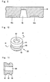
- Fig. 10 is an entirely perspective view showing the structure of the packing component 80
- Fig. 11 is a cross sectional view at the line XI-XI in Fig. 10.
- This packing component 80 is of a ring shape, and the external circumferential surface consists of an upper ring convex portion 81, an lower ring convex portion 83, and a portion pinched by the upper ring convex portion 81 and the lower ring convex portion 83, and an engaging concave portion 82 to which an engaging convex portion 56a arranged on the air pressure outlet 56 is arranged therein.
- a through path 84 expanding in axial direction is arranged.
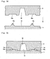
- Fig. 12 and Fig. 13 are cross sectional views showing the welding conjunction structure of the external circumferential convex portion 11a of the filter case 10, and the external circumferential concave portion 51a of the-filter cap 50
- Fig. 14 and Fig. 15 are cross sectional views showing the welding conjunction structure of the first convex portion 14a of the filter case 10, and the second concave portion 54a of the filter cap 50.
- the welding conjunction structure of the second convex portion 16a of the filter case 10, and the second concave portion 54a of the filter cap 50 is same as that shown in Fig. 14 and Fig. 15, therefore the explanation thereof is omitted herein.
- a welding conjunction structure by ultrasonic welding is adopted wherein the concave portions (11a, 14a, and 16a) arranged on the filter case 10 and the concave portions (51a, 52a, and 54a) arranged on the filter cap are mated, it is possible to attain sufficient bonding strength and air tightness in welded portions, and sufficient pressure durability performance against air pressure.
- the structure according to the present invention has the first capillary 1A, the first tank 1B, the second capillary 1C, and the second tank 1D that are connected in series respectively, and the first capillary 1A and the second capillary 1C, and the first tank 1B and the second tank 1D are arranged on diagonal lines respectively, as a consequence, the close adhesion of the convex portions as part of the welding conjunction structure is relatively even, and it is possible to carry out even welding. As a result, welding failure scarcely occurs.
- a ring-shaped packing component 80 to the air pressure outlet 56, it is possible to enhance the air tightness in the air pressure outlet 56. And by arranging engaging portions (56a and 82) that engage with each other between the air pressure outlet 56 and the packing component 80, it becomes possible to prevent the packing component 80 from coming out from the air pressure outlet 56. Still further, by arranging a contact material 18 to which the packing component 80 contacts in the acoustic filter near the air pressure outlet 56, it becomes possible to prevent the packing component 80 from encroaching into the inside of the acoustic filter 1.
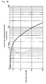
- Fig. 16 shows acoustic filter frequency characteristics, wherein the attenuation ratio (dB) is shown in the vertical axis, while the frequency (Hz) is shown in the horizontal axis by logarithmic divisions.
- the frequency at which the attenuation ratio (dB) is -3 (dB) is defined as cut-off frequency, and the cut-off frequency in this case is approximately 16 (Hz).
- the present invention is not limited to the arrangement, but it is also possible to adopt a structure wherein capillaries are arranged on one side, and tanks are arranged on the other side.
- the quantity of capillaries and tanks may be selectively decided at necessity so as to attain required characteristics of an acoustic filter, and is not limited to the quantity mentioned in the embodiment.
- the arrangement of capillaries may be varied as a design particular so as to obtain filter effects, and is not limited to the arrangement mentioned in the embodiment.
- a welding conjunction structure by ultrasonic welding wherein convex portions arranged on one side and concave portions arranged on the other side are engaged with each other, however, the conjunction method is not limited to this ultrasonic welding, but other conjunction methods may be adopted.
- tank and capillary lid portions and corresponding tank and capillary formation portions may be arranged respectively to one of the filter case and the filter cap, therefore, their structure is not limited to the structure mentioned in the embodiment.
- an acoustic filter under the present invention wherein a structure without a packing as seen in prior art is adopted, it is possible to stabilize the characteristics of an acoustic filter without giving any influence upon the spatial capacity of a tank and that of a capillary.
Landscapes
- Health & Medical Sciences (AREA)
- Life Sciences & Earth Sciences (AREA)
- Cardiology (AREA)
- Vascular Medicine (AREA)
- Engineering & Computer Science (AREA)
- Physics & Mathematics (AREA)
- Heart & Thoracic Surgery (AREA)
- Surgery (AREA)
- Veterinary Medicine (AREA)
- Biophysics (AREA)
- Pathology (AREA)
- Biomedical Technology (AREA)
- Public Health (AREA)
- Medical Informatics (AREA)
- Molecular Biology (AREA)
- Physiology (AREA)
- Animal Behavior & Ethology (AREA)
- General Health & Medical Sciences (AREA)
- Acoustics & Sound (AREA)
- Multimedia (AREA)
- Ophthalmology & Optometry (AREA)
- Lining Or Joining Of Plastics Or The Like (AREA)
- Measuring Pulse, Heart Rate, Blood Pressure Or Blood Flow (AREA)
- Filtering Of Dispersed Particles In Gases (AREA)
- Measuring Fluid Pressure (AREA)
Applications Claiming Priority (2)
| Application Number | Priority Date | Filing Date | Title |
|---|---|---|---|
| JP2001362993A JP3738729B2 (ja) | 2001-11-28 | 2001-11-28 | 血圧計の音響フィルタ |
| JP2001362993 | 2001-11-28 |
Publications (2)
| Publication Number | Publication Date |
|---|---|
| EP1316943A2 true EP1316943A2 (fr) | 2003-06-04 |
| EP1316943A3 EP1316943A3 (fr) | 2003-12-17 |
Family
ID=19173408
Family Applications (1)
| Application Number | Title | Priority Date | Filing Date |
|---|---|---|---|
| EP02024936A Withdrawn EP1316943A3 (fr) | 2001-11-28 | 2002-11-06 | Filtre acoustique |
Country Status (4)
| Country | Link |
|---|---|
| US (1) | US20030098199A1 (fr) |
| EP (1) | EP1316943A3 (fr) |
| JP (1) | JP3738729B2 (fr) |
| CN (2) | CN1422592A (fr) |
Cited By (1)
| Publication number | Priority date | Publication date | Assignee | Title |
|---|---|---|---|---|
| WO2007051272A1 (fr) * | 2005-11-04 | 2007-05-10 | Whirlpool S.A. | Silencieux acoustique pour compresseur hermétique |
Families Citing this family (8)
| Publication number | Priority date | Publication date | Assignee | Title |
|---|---|---|---|---|
| US20050031462A1 (en) * | 2003-08-07 | 2005-02-10 | Chi-Der Chen | Silent device for submerge pump of aquarium |
| US20050051384A1 (en) * | 2003-09-10 | 2005-03-10 | Breznik Evelyn A. | Air intake silencer |
| US7165647B2 (en) * | 2003-12-18 | 2007-01-23 | Pei-Chau Lee | Mechanical acoustic filter by erosion etching |
| KR101377304B1 (ko) * | 2007-07-27 | 2014-03-26 | 엘지전자 주식회사 | 밀폐형 압축기의 흡입소음기 |
| JP5353268B2 (ja) | 2009-01-28 | 2013-11-27 | オムロンヘルスケア株式会社 | ダイヤフラムポンプおよび血圧計 |
| JP5528272B2 (ja) * | 2010-09-15 | 2014-06-25 | 株式会社エー・アンド・デイ | 自動血圧測定装置 |
| KR102253640B1 (ko) * | 2019-03-27 | 2021-05-18 | 주식회사 셀바스헬스케어 | 혈압 측정 장치 |
| KR102253639B1 (ko) * | 2019-03-27 | 2021-05-18 | 주식회사 셀바스헬스케어 | 혈압 측정 장치 |
Citations (9)
| Publication number | Priority date | Publication date | Assignee | Title |
|---|---|---|---|---|
| GB360686A (en) * | 1930-11-20 | 1931-11-12 | Paul Barringhaus | Exhaust silencer for internal combustion engines |
| FR1368204A (fr) * | 1963-06-17 | 1964-07-31 | Duralumin | Silencieux d'échappement |
| JPS5943917A (ja) * | 1982-09-02 | 1984-03-12 | Sanyo Electric Co Ltd | 圧縮機の吸込マフラ製造方法 |
| DE3240710A1 (de) * | 1982-11-04 | 1984-05-10 | Festo-Maschinenfabrik Gottlieb Stoll, 7300 Esslingen | Entlueftungsschalldaempfer |
| US4759693A (en) * | 1986-07-09 | 1988-07-26 | Danfoss A/S | Suction sound damper |
| JPH07210167A (ja) * | 1994-01-19 | 1995-08-11 | Omron Corp | 音響フィルタ |
| US5722237A (en) * | 1995-10-20 | 1998-03-03 | Kioritz Corporation | Muffler structure for internal combustion engine |
| EP0902184A2 (fr) * | 1997-09-11 | 1999-03-17 | Clam S.p.A. | Procédé de production d'un amortisseur de son pour une ouverture d'admission de fluide partculièrement adapté pour des circuits de compression des installations de réfrigération |
| EP1088993A1 (fr) * | 1999-04-15 | 2001-04-04 | Matsushita Refrigeration Company | Silencieux d'aspiration et compresseur electrique ferme |
-
2001
- 2001-11-28 JP JP2001362993A patent/JP3738729B2/ja not_active Expired - Lifetime
-
2002
- 2002-11-05 US US10/287,791 patent/US20030098199A1/en not_active Abandoned
- 2002-11-06 EP EP02024936A patent/EP1316943A3/fr not_active Withdrawn
- 2002-11-28 CN CN02154302.XA patent/CN1422592A/zh active Pending
- 2002-11-28 CN CN02287444.5U patent/CN2602724Y/zh not_active Expired - Lifetime
Patent Citations (9)
| Publication number | Priority date | Publication date | Assignee | Title |
|---|---|---|---|---|
| GB360686A (en) * | 1930-11-20 | 1931-11-12 | Paul Barringhaus | Exhaust silencer for internal combustion engines |
| FR1368204A (fr) * | 1963-06-17 | 1964-07-31 | Duralumin | Silencieux d'échappement |
| JPS5943917A (ja) * | 1982-09-02 | 1984-03-12 | Sanyo Electric Co Ltd | 圧縮機の吸込マフラ製造方法 |
| DE3240710A1 (de) * | 1982-11-04 | 1984-05-10 | Festo-Maschinenfabrik Gottlieb Stoll, 7300 Esslingen | Entlueftungsschalldaempfer |
| US4759693A (en) * | 1986-07-09 | 1988-07-26 | Danfoss A/S | Suction sound damper |
| JPH07210167A (ja) * | 1994-01-19 | 1995-08-11 | Omron Corp | 音響フィルタ |
| US5722237A (en) * | 1995-10-20 | 1998-03-03 | Kioritz Corporation | Muffler structure for internal combustion engine |
| EP0902184A2 (fr) * | 1997-09-11 | 1999-03-17 | Clam S.p.A. | Procédé de production d'un amortisseur de son pour une ouverture d'admission de fluide partculièrement adapté pour des circuits de compression des installations de réfrigération |
| EP1088993A1 (fr) * | 1999-04-15 | 2001-04-04 | Matsushita Refrigeration Company | Silencieux d'aspiration et compresseur electrique ferme |
Non-Patent Citations (2)
| Title |
|---|
| PATENT ABSTRACTS OF JAPAN vol. 008, no. 146 (M-307), 7 July 1984 (1984-07-07) & JP 59 043917 A (SANYO DENKI KK;OTHERS: 01), 12 March 1984 (1984-03-12) * |
| PATENT ABSTRACTS OF JAPAN vol. 1995, no. 11, 26 December 1995 (1995-12-26) & JP 07 210167 A (OMRON CORP), 11 August 1995 (1995-08-11) * |
Cited By (1)
| Publication number | Priority date | Publication date | Assignee | Title |
|---|---|---|---|---|
| WO2007051272A1 (fr) * | 2005-11-04 | 2007-05-10 | Whirlpool S.A. | Silencieux acoustique pour compresseur hermétique |
Also Published As
| Publication number | Publication date |
|---|---|
| CN1422592A (zh) | 2003-06-11 |
| JP3738729B2 (ja) | 2006-01-25 |
| JP2003162283A (ja) | 2003-06-06 |
| CN2602724Y (zh) | 2004-02-11 |
| US20030098199A1 (en) | 2003-05-29 |
| EP1316943A3 (fr) | 2003-12-17 |
Similar Documents
| Publication | Publication Date | Title |
|---|---|---|
| EP1316943A2 (fr) | Filtre acoustique | |
| US4828694A (en) | Filter with filtration envelope spacing means | |
| US9237854B2 (en) | Valve, fluid control device | |
| US4783260A (en) | Filter device in a fuel tank having angularly oriented suction port, and integral spacers | |
| EP1481716B1 (fr) | Filtre pour moteur et transmission à flux rentrant et procédé | |
| US6464872B1 (en) | Fuel filter with inlet holding member | |
| EP1306119A2 (fr) | Filtre pour réservoir à carburant | |
| US20210324844A1 (en) | Piezoelectric pump | |
| KR100401679B1 (ko) | 필터장치 | |
| JPH11141417A (ja) | サージタンク | |
| JP2002364325A (ja) | 内燃機関のオイルパンバッフルプレート | |
| JP5668582B2 (ja) | 流体制御装置 | |
| US6706183B2 (en) | Filter | |
| EP0350813A2 (fr) | Objet moulé en matière plastique, procédé pour sa fabrication et évent muni de cet objet | |
| JP2003162283A5 (fr) | ||
| JP2005248945A (ja) | エンジンフィルタ又はトランスミッションフィルタにおけるフィルタ媒体の支持装置又は方法 | |
| JP2003533341A (ja) | ハウジング長手軸に垂直な平面に対し斜めの溶接シームを備えるプラスチック・フィルタ・ハウジング | |
| JPS6287216A (ja) | 燃料タンク用ストレ−ナ及びその製造方法 | |
| JP3046268B2 (ja) | 燃料ポンプのフィルタ装置 | |
| JP4637407B2 (ja) | ストレーナ | |
| JP2002106468A (ja) | ダイヤフラムポンプ | |
| JPH09150022A (ja) | フィルタ | |
| CN219814891U (zh) | 输液过滤器 | |
| JPH0587044A (ja) | エアーポンプのフイルター部の構造 | |
| CN218096715U (zh) | 一种贮液器 |
Legal Events
| Date | Code | Title | Description |
|---|---|---|---|
| PUAI | Public reference made under article 153(3) epc to a published international application that has entered the european phase |
Free format text: ORIGINAL CODE: 0009012 |
|
| AK | Designated contracting states |
Designated state(s): AT BE BG CH CY CZ DE DK EE ES FI FR GB GR IE IT LI LU MC NL PT SE SK TR |
|
| AX | Request for extension of the european patent |
Extension state: AL LT LV MK RO SI |
|
| PUAL | Search report despatched |
Free format text: ORIGINAL CODE: 0009013 |
|
| AK | Designated contracting states |
Kind code of ref document: A3 Designated state(s): AT BE BG CH CY CZ DE DK EE ES FI FR GB GR IE IT LI LU MC NL PT SE SK TR |
|
| AX | Request for extension of the european patent |
Extension state: AL LT LV MK RO SI |
|
| RIC1 | Information provided on ipc code assigned before grant |
Ipc: 7F 01N 7/00 B Ipc: 7G 10K 11/04 A |
|
| RAP1 | Party data changed (applicant data changed or rights of an application transferred) |
Owner name: OMRON HEALTHCARE CO., LTD. |
|
| 17P | Request for examination filed |
Effective date: 20040128 |
|
| 17Q | First examination report despatched |
Effective date: 20040402 |
|
| AKX | Designation fees paid |
Designated state(s): DE FR GB IT |
|
| STAA | Information on the status of an ep patent application or granted ep patent |
Free format text: STATUS: THE APPLICATION IS DEEMED TO BE WITHDRAWN |
|
| 18D | Application deemed to be withdrawn |
Effective date: 20040813 |