EP1315009A2 - Module de distribution et de connexion de fibres optiques destiné à un répartiteur optique - Google Patents
Module de distribution et de connexion de fibres optiques destiné à un répartiteur optique Download PDFInfo
- Publication number
- EP1315009A2 EP1315009A2 EP02292794A EP02292794A EP1315009A2 EP 1315009 A2 EP1315009 A2 EP 1315009A2 EP 02292794 A EP02292794 A EP 02292794A EP 02292794 A EP02292794 A EP 02292794A EP 1315009 A2 EP1315009 A2 EP 1315009A2
- Authority
- EP
- European Patent Office
- Prior art keywords
- cassette
- arm
- fiber
- fibers
- module according
- Prior art date
- Legal status (The legal status is an assumption and is not a legal conclusion. Google has not performed a legal analysis and makes no representation as to the accuracy of the status listed.)
- Granted
Links
- 239000013307 optical fiber Substances 0.000 title claims abstract description 19
- 230000003287 optical effect Effects 0.000 title claims abstract description 18
- 239000000835 fiber Substances 0.000 claims abstract description 79
- 230000000295 complement effect Effects 0.000 claims description 15
- 230000005540 biological transmission Effects 0.000 claims description 10
- 238000009434 installation Methods 0.000 description 5
- 238000012423 maintenance Methods 0.000 description 3
- 238000000034 method Methods 0.000 description 3
- 230000004308 accommodation Effects 0.000 description 2
- 235000021028 berry Nutrition 0.000 description 2
- 238000006073 displacement reaction Methods 0.000 description 2
- 239000007787 solid Substances 0.000 description 2
- 238000013519 translation Methods 0.000 description 2
- 238000005452 bending Methods 0.000 description 1
- 239000000470 constituent Substances 0.000 description 1
- 238000002788 crimping Methods 0.000 description 1
- 230000006866 deterioration Effects 0.000 description 1
- 238000010494 dissociation reaction Methods 0.000 description 1
- 230000005593 dissociations Effects 0.000 description 1
- 238000009432 framing Methods 0.000 description 1
- 238000003780 insertion Methods 0.000 description 1
- 230000037431 insertion Effects 0.000 description 1
- 239000011810 insulating material Substances 0.000 description 1
- 238000009413 insulation Methods 0.000 description 1
- 230000000670 limiting effect Effects 0.000 description 1
- 239000000463 material Substances 0.000 description 1
- 239000011159 matrix material Substances 0.000 description 1
- 238000012986 modification Methods 0.000 description 1
- 230000004048 modification Effects 0.000 description 1
- 210000000056 organ Anatomy 0.000 description 1
- 230000008520 organization Effects 0.000 description 1
- 230000036961 partial effect Effects 0.000 description 1
- 230000035515 penetration Effects 0.000 description 1
- 238000003825 pressing Methods 0.000 description 1
- 230000001681 protective effect Effects 0.000 description 1
- 230000008521 reorganization Effects 0.000 description 1
- 230000000717 retained effect Effects 0.000 description 1
- 230000002441 reversible effect Effects 0.000 description 1
- 239000011800 void material Substances 0.000 description 1
Images



Classifications
-
- G—PHYSICS
- G02—OPTICS
- G02B—OPTICAL ELEMENTS, SYSTEMS OR APPARATUS
- G02B6/00—Light guides; Structural details of arrangements comprising light guides and other optical elements, e.g. couplings
- G02B6/24—Coupling light guides
- G02B6/36—Mechanical coupling means
- G02B6/38—Mechanical coupling means having fibre to fibre mating means
- G02B6/3807—Dismountable connectors, i.e. comprising plugs
- G02B6/3873—Connectors using guide surfaces for aligning ferrule ends, e.g. tubes, sleeves, V-grooves, rods, pins, balls
- G02B6/3885—Multicore or multichannel optical connectors, i.e. one single ferrule containing more than one fibre, e.g. ribbon type
-
- G—PHYSICS
- G02—OPTICS
- G02B—OPTICAL ELEMENTS, SYSTEMS OR APPARATUS
- G02B6/00—Light guides; Structural details of arrangements comprising light guides and other optical elements, e.g. couplings
- G02B6/44—Mechanical structures for providing tensile strength and external protection for fibres, e.g. optical transmission cables
- G02B6/4439—Auxiliary devices
- G02B6/444—Systems or boxes with surplus lengths
- G02B6/4452—Distribution frames
- G02B6/44524—Distribution frames with frame parts or auxiliary devices mounted on the frame and collectively not covering a whole width of the frame or rack
-
- G—PHYSICS
- G02—OPTICS
- G02B—OPTICAL ELEMENTS, SYSTEMS OR APPARATUS
- G02B6/00—Light guides; Structural details of arrangements comprising light guides and other optical elements, e.g. couplings
- G02B6/44—Mechanical structures for providing tensile strength and external protection for fibres, e.g. optical transmission cables
- G02B6/4439—Auxiliary devices
- G02B6/444—Systems or boxes with surplus lengths
- G02B6/4453—Cassettes
- G02B6/4455—Cassettes characterised by the way of extraction or insertion of the cassette in the distribution frame, e.g. pivoting, sliding, rotating or gliding
-
- G—PHYSICS
- G02—OPTICS
- G02B—OPTICAL ELEMENTS, SYSTEMS OR APPARATUS
- G02B6/00—Light guides; Structural details of arrangements comprising light guides and other optical elements, e.g. couplings
- G02B6/24—Coupling light guides
- G02B6/36—Mechanical coupling means
- G02B6/38—Mechanical coupling means having fibre to fibre mating means
- G02B6/3807—Dismountable connectors, i.e. comprising plugs
- G02B6/3873—Connectors using guide surfaces for aligning ferrule ends, e.g. tubes, sleeves, V-grooves, rods, pins, balls
- G02B6/3874—Connectors using guide surfaces for aligning ferrule ends, e.g. tubes, sleeves, V-grooves, rods, pins, balls using tubes, sleeves to align ferrules
Definitions
- the invention relates to a distribution and connection module for optical fibers intended for an optical distributor itself intended to allow the interconnections which are to be made selectively between links by optical fibers in a telecommunications installation comprising a high number of these fiber links.
- FIG. 1 An example of an optical distributor for installation of telecommunications is described in US Patent 5,497,444. illustrated in FIG. 1 and it comprises a framework 1, of rectangular appearance, which carries a series of horizontal supports 2 on which come position modules 3, which are distributed on the supports so as to constitute two parallel vertical subsets. Each module is designed to accommodate several fittings, each fitting being provided for allow the interconnection of two fibers, one of which is used as that garter. Such interconnection between two fibers is carried out by by means of two connecting members which are each mounted at the end of a fiber and which are positioned opposite each other at a connection. The fiber connecting members serving jumpers are positioned in front of the fittings in the distributor while the connecting members of the other fibers which they serve to interconnect are positioned behind. Guide and support elements are designed to allow the movement of garters between the connections taking into account future reorganization needs, they are represented by split passage rings 4 and chutes 5, in figure 1.
- the garters circulate in general, either horizontally in horizontal troughs and in particular the chutes associated with the horizontal supports of the modules, either vertically and more particularly in split rings defining a vertical guide at each of the width ends of the distributor.
- the optical jumpers which are usually produced in the factory, are generally of a length determined sufficient to allow a connection between the elements of connection farthest from the distributor and the garters uniting less distant connection elements must be coiled so as to place their respective extra lengths in the distributor. This accommodation takes place, for example, inside or near the vertical guides and must therefore be specifically provided for.
- an arrangement of fiber optic distribution and connection module comprising a plurality of connection supports, each comprising a hollow arm sliding in a housing and fitted at one end with a connector and at the other end of an optical fiber coiling cassette connected to said connector inside said arm. The other end of each optical fiber is connected to the optical transmission or distribution.
- the arm is slid outside of the case with the coiling cassette which is rigidly fixed. If thanks to the extra length of the fiber, the latter can stay connected to the cable at one end, the connector with the other fiber end is imperatively disconnected. In other words, any operation on the section of optical fiber located in the coiling causes a displacement of all the optical fiber arranged in the housing. This leads to particularly heavy interventions.
- the invention solves these problems by proposing a module for distribution and connection allowing operations on optical fiber coiled in the cassette without the need for disconnection and without large size, while providing a particularly distribution compact particularly suitable for a high density distributor.
- the invention proposes a distribution and fiber optic connection for an optical splitter, the first end of each fiber being connected to a connection base and the second end of each fiber being connected to an optical cable of transmission or distribution, module comprising a guide arm of each fiber fixed by its first end on a row support connection bases and connected by its second end to a cassette coiling of each fiber, characterized in that said coiling cassette is mounted on said arm by means of a joint.
- articulation of a cassette on a support arm fixed in a distributor allows it to be moved between positions that correspond to one at a normal operating position for which it is inserted between two other cassettes with which it is then aligned and a position conducive to interventions for which it is almost completely out of the alignment of cassettes in which it is normally incorporated.
- said arm is fixed.
- said arm comprises, at its second end, an articulation element for said cassette constituted of a horizontal pivot.
- this pivot projects laterally from an extension plan of the bottom of a U-shaped channel formed by the arm.
- This U-shaped channel is intended for the passage and holding in place of intermediate bonding fibers between the individual connection elements of the base, housed in the arm, and the connecting fibers, which come from transmission or distribution cables leading to the distributor and which have a coiled end connected by a splice to one of said fibers linking intermediaries in the coiling cassette carried by the arm.
- This articulation element projecting laterally from a plan extension of the bottom of the U-shaped channel for intermediate fibers than forms the arm, frees the passage for these intermediate fibers towards the inside of the cassette carried by the arm, whatever the position of this cassette in relation to the arm that carries it.
- said cassette comprises a articulation element, formed by a pivot bearing, complementary to the articulation element carried by the support arm.
- the complementary articulation element carried by said cassette is surrounded by two fiber conduits, a first of these conduits, made towards the inside of the cassette with respect to each other and to the complementary articulation element which it adjoins, being intended for the passage of the fiber towards the arm carrying the cassette, when the latter is carried by through the complementary hinge element that this first adjacent duct, the second of these conduits, directed towards the outside of the cassette with respect to the first conduit and the articulation element which it adjoins, being intended for the passage of fibers emanating from transmission or distribution cables which are connected to the cassette.
- said cassette comprises two articulation elements, symmetrically arranged with respect to the transverse plane at the level of ends of one of the long sides of the case formed by the cassette articulated by one or the other of these two articulation elements additional depending on the mounting provided for the arm.
- said arm is doubly bent in the opposite direction in two dimensions and preferably mid-length.
- the arms constituting the individual support elements of the bases and the coiling cassettes at bay level are arranged to be able to be assembled in groups each bringing together the bases of two neighboring rows which are each fixed on two parallel supports of which one is common to them and along which the arms are alternately positioned, one above and the next below.
- Said arms identical to each other, being doubly bent in direction reverse in two dimensions allow the coiling tapes, respectively carried by alternating arms on either side of one of the parallel supports which is common to a group, to be arranged in a same alignment inside the bay, when in position due to the alignment of the articulation elements for cassettes that these arms alternate on either side of the same common support and respective sizes of cassettes and arms.
- This curvature along two perpendicular axes of the arm allows an arrangement of two arms overlapping head to tail in a limited width at the positioning steps of a module.
- said coiling cassette carries a pawl latching intended to cooperate with a corresponding orifice of the arm.
- Figure 1 corresponds to a perspective view of the distributor known optics succinctly described above.
- Figure 2 shows an example of a known connection base and a plug, as envisaged in a distributor according to the invention.
- FIG. 3 presents a front view of an optical distributor according to the invention.
- Figure 4 shows a right view of the optical distributor of the figure 2.
- Figure 5 shows a partial perspective view of a detail of embodiment relating to the distributor illustrated in FIGS. 3 and 4.
- Figures 6 and 7 show a perspective view and a view of above an example of a support arm for a connection base of a optical distributor according to the invention.
- Figure 8 shows a perspective view of a coiling cassette fiber of an optical distributor according to the invention.
- Figures 9 and 10 are perspective views of a module according to the invention.
- FIG. 2 An example of a multipoint optical base 6, likely to be pre-wired is illustrated, by way of example in FIG. 2.
- This base is designed to allow the individual connection of a given number of jumpers J, assumed to be composed of a single optical fiber in the example given, to a corresponding number of optical fibers F most generally from the same transmission or distribution cable of an installation.
- the garters and the fibers to which they connect are equipped additional individual connection elements.
- the garters are assumed to be fitted with male plugs connection, individual, such as the straight 8 'tubular plug mounted in end of a section of garter J in FIG.
- connection 8 complementary, here aligned, which lead to a face, called front, 9 of the base, as also seen in FIG. 2.
- a base allows for example to connect optical fibers forming part of the same group 7 and for example of a group 7 of eight fibers of a cable.
- Each connection element 8 is arranged to receive on the one hand, a fiber for example of a cable and, on the other hand, a plug terminating a fiber of garter, the two fibers coming to position end to end one by compared to each other.
- Connection plugs are for example under the form of tubular plugs, which are intended to be longitudinally each crossed by a garter fiber.
- This fiber just ended at a plug-in end of the plug it crosses and in which it is immobilized.
- This immobilization is, for example obtained by crimping.
- the plug-in end is produced in a manner known per se to position itself in a duct provided for it in an element connection 8, complementary, it is likely to be elastically retained in position in this element, after plugging in, if this is considered as preferable.
- it is provided for minus one and preferably two positioning marks 0, 0 'for each base, these marks being here constituted by two vertically holes aligned, if we consider the front face of the base as being in a vertical reference plane.
- garters which are different from those envisaged above and for example garters made up of cables comprising several fibers, fibers under loose or tight insulation, multi-fiber ribbons as part of a distributor according to the invention.
- Appropriate plugs and sockets are then provided for these different cases. Known in themselves they will not be described in detail here.
- the garters considered in the following description are considered to be each composed of a single optical fiber in the following description. It should however be understood that the invention relates to a method of jumper and distributors that can be used with garters of different types as envisaged above.
- FIG. 3 and 4 A non-limiting example of an optical distributor for installation of telecommunications, according to the invention is shown in Figures 3 and 4. It is assumed to be of large capacity and high density of elements, or points, connection and it has at least one and here two distribution bays aligned, such as 11A and 11B, which each have a set of bases, as envisioned above. These bases are intended to allow a selective interconnection between cables of transmission cables or distribution which lead to the distributor, this interconnection being carried out by means of garters whose ends are equipped with plugs compatible with the connection elements that have the bases.
- the two bays 11A, 11B are separated from each other by a patching zone 12 allowing the passage of the garters connecting the bases comprised by one of the bays with those that the other comprises, the bays being most generally specialized, one being for example assigned to the outgoing connections and the other to the arrival connections.
- the number of bays is greater than two, it is of course possible to provide for the passage of the garters, either at a single patching zone between two of the bays, or in zones each distributed between two bays, if necessary. East.
- a patching zone allowing vertical circulation of the garters on at least one of the sides of the bay.
- the bases are assumed to be of the type shown in FIG. 2, they are gathered in rows in structures with matrix look where their front faces are preferably arranged coplanar way. Locating means are provided to allow know the position of each base in the assembly formed by all manifold sub-bases and each point belonging to one of these bases and corresponding to an individual connection element.
- the bases are arranged in parallel horizontal rows which are preferably aligned from one bay to another, when there are several bays and which are identically referenced 10A or 10B, depending on the rack which contains them, in the example shown.
- the bases 6 are mounted on profiles horizontal that each of the bays have at one face, called before, two of these sections respectively referenced 13A and 13B being shown, without base, in Figure 3.
- the parallel rows of bases are interrupted at the level of the mixing zone 12 which separates the berries neighbors.
- the means for locating the positions of the bases which are provided at the distributor are for example constituted by openings regularly spaced at the step of the bases on the horizontal profiles where these bases are mounted, or possibly on elements of the distributor which are fixedly associated with these profiles and for example horizontal chutes individually associated with these profiles.
- These means marking are for example holes 67 regularly formed in the profiles or in trunking, as illustrated for 13B profiles or chutes 16B in FIG. 5. They can also be in the form notches 68 regularly produced along these profiles or chutes, as illustrated in FIG. 16, or even optical markers, for example target or barcode type.
- connection to bases 6, of fibers from different transmission and distribution cables, involves the use of means specific materials which are organized here in distribution modules and connection.
- These modules are in the form of cassettes individually articulated on individual support elements here made in the form of arms. They are housed in the internal volume proper to each of the bays so that the bases, which they carry, have their coplanar front faces.
- the interior volumes specific to the bays are delimited by the framework of beams serving as support elements and connection to the distributor, such as the vertical beams 14 and horizontal 15 of the bays 11A and 11B, in FIGS. 3 and 4.
- the sections 13A and 13B, which support the rows of bases are fixed on the vertical beams 14 framing the front face of the bay which include them.
- a horizontal chute is associated with each row base, these chutes being identically referenced 16A or 16B for the different rows, in FIG. 3, along the bay, either here 11A or 11B, that they equip.
- Each of these chutes 16A or 16B is intended to receive the optical fibers constituting the garters which are connected to the connection elements 8 of the sockets 6 whose cells are located immediately above, as shown in Figure 5 for one of the 16B trunking.
- Garter guide elements 17 are fixed on the profiles of support of the bases so as to run from top to bottom along the alveoli connection elements 8 of each base 6, above each horizontal chute. These elements are arranged to guide each garter between the trough where it comes to rest and one of the cells a base located immediately above this chute. These garter guide elements 17 are made so as to facilitate removal garters in the trunking and their adjustment in length and tension, avoiding crossings between neighboring garters, at their level.
- the patching area 12 formed between neighboring bays is here assumed to be dimensioned to allow the passage of all of the garters which are likely to be put in place to connect, each, a connection element 8 of a base 6 of a bay to an element of connection of a base of the other bay.
- This implementation is planned whatever the respective positions of the elements, of the bases which include them, and chutes associated with these bases in the bays.
- connection elements forming part of bases which are located at different heights in two bays which include them
- this circulates in a mixing zone 12, so as to pass from the vertical level of the chute which serves one of the manifolds to that of the chute serving the other.
- the set consisting of the garters passing through a patching area 12 is maintained in a determined position inside this zone 12, by means of guides here called general, such as 18A or 18B responsible for ensuring maintenance and protection of the garters.
- the general guides are here supposed to be associated in pairs, the two general guides of a pair being respectively mounted on the same level vertical on either side of a mixing zone 12 formed between two neighboring bays.
- the two general guides 18B which are represented are each located in the extension of the front edge of a chute 16B. They are intended for keep the circulating garters in the brewing zone 12 vertically at their respective levels and which pass through chutes the bay comprising the chute in the extension of which each of them is respectively located.
- Closure plates 69 carried by beams of the distributor frame limit the patching area 12 behind the general guides, as shown in figure 3.
- the bases 6 are carried by individual support arms which are fixed side by side on horizontal profiles, such as support arms 19 and 19 ' which are partially visible in Figure 5 and one of which is detailed on the Figure 6.
- Each of these support arms has a housing opening at one of its ends which is arranged to allow it to receive a base, it is here provided that the support arms are fixed on the horizontal base support profiles, as shown in figure 5 for arms 19, 19 '.
- Profiles such as 13A, 13B, are made so to allow positioning of the arms and consequently of the bases, as symbolized by the ribs 20 present on the two sections 13B, located in the high position in Figure 5.
- FIG. 6 An embodiment of a support arm 19 is illustrated in the Figures 6 and 7, as indicated above, this arm has a housing central 21 formed at a first of its ends to receive a base 6 which is positioned there precisely so that the face front and the cells of the connection elements that this base comprises, are in predetermined positions. From the moment it is planned an automated jumper between base connection elements different, it is necessary to have means to obtain the positioning of the plugs which terminate the garters in the conduits of the connection elements 8 where these plugs are to be inserted.
- means are provided for level of the end of a support arm which has a central housing 21 to cooperate with additional means provided at the level of a device by which a plug is positioned in front of the cell connection element 8 into which it must be introduced.
- the means provided at the end of an arm support are hollow forms intended to receive solid forms complementary, these forms are chosen to allow obtaining the positioning accuracy required for the introduction of a connection position in a conduit of a connection element whose position in the dispatcher has been predetermined.
- the means provided at the end of an arm of support are formed in the form of cylindrical cavities 22A which are formed at the first end of each arm and laterally each extended by a slot 22B of determined orientation.
- Base 6 is immobilized in the arm in a determined position, this positioning being confirmed by a 22C polarizer internally formed at arm level so as to enter one of the holes 0 or 0 ' which constitute the positioning marks of a base 6, when this base is in the position provided for it in the arm, the hole to be used being predetermined.
- cavities 22A are provided. arranged around the opening of the housing 21 provided for a base 6 to the first end of a support arm 19. These cavities 22A are connected two by two by a slot 22B which is common to them and which is oriented parallel to the alignment axis provided for the cells of the connection 8 of the base 6 which is housed in the arm shown.
- a rod centering preferably cylindrical and the diameter of which then corresponds to that of a cavity 22A, serves as a complementary solid form for the device designed to allow the positioning of a plug.
- This rod centering extends laterally by a projecting part whose dimensions correspond to those of a slot 22B where it comes position, when the rod which carries it is in a cavity 22A, so to provide a precise indication of positioning to the device that it team.
- a projecting part whose dimensions correspond to those of a slot 22B where it comes position, when the rod which carries it is in a cavity 22A, so to provide a precise indication of positioning to the device that it team.
- four cylindrical cavities 22A and two slots 22B are provided. support arm.
- the precise placement of the plug positioning device can be obtained by relative to one of the cylindrical cavities 22A which are arranged around the housing opening 21 of a support arm 19.
- the device position is mechanically moved to position in a predetermined way with respect to the distributor or more precisely to a connection element 8 of a base 6 precisely positioned in one of the dispatcher bays.
- the penetration of the centering rod of the plug positioning device in a cylindrical cavity 22A is then liable to be exploited incidentally for a prepositioning of the tool of this device which is used to insert a plug in the conduit of a connection element 8 determined from a base 6 determined.
- the tool is then produced in such a way that the plug has a certain possibility of accommodation and has a relative freedom of lateral movement at insertion.
- This possibility is for example the consequence of the presence of one or more springs at the level of the fixing of said tool on the device which carries it.
- the arm is doubly angled in the opposite direction at least approximately mid-length and in two dimensions, as shown in Figures 6 and 7, its two ends therefore being offset from each other, this arrangement is intended to allow high density mounting of the 19.19 'arms, bases 6 and cassettes 23 for coiling the fibers constituting the garters, at a distributor, as illustrated on the detail of realization of figure 5.
- the first end of a arm cooperates with two immediately adjacent support profiles a bay between which it plugs.
- it has two slots positioning 25 arranged to slide on ribs 20 opposite the same horizontal level which are comprised by the profiles of support between which is inserted said first arm end, the slots being shown in FIGS. 6 and 7, the ribs in FIG. 5.
- the second end of an arm has a hinge element 26 which is here constituted by a lateral axis intended to be horizontal, when the arm is in place in a distributor.
- This articulation element 26 is intended to serve as support for a cassette, as succinctly mentioned above, which has for this purpose a complementary articulation element, here of the kind carried for axis, as seen in Figure 8.
- the double folded structure which joins the two ends of a arm is here supposed to be constituted by a hollow body delimiting a channel U-shaped side which ends in the housing 20 of a base 6 to a end and by an extension of the bottom of the U which carries the element axis hinge 26.
- This lateral channel is designed to allow the passage of the group 7 of fibers which connect the connection elements of a base 6 to a coiling cassette.
- it has a labyrinth which consists of retaining tabs 27 extending above the bottom of the channel, from the two banks from which these legs project alternately from one bank to the other, so as to maintain the fibers in the channel after they are there have been introduced.
- the dimension from the end of the arm and here from its front face, in a parallel direction 13B profiles between which it is positioned is chosen double the width L of the other parts of the arm and of the cassette according to this same direction.
- This arrangement allows a gain in base density insofar as it makes it possible to alternate structures belonging to arms support on which are mounted bases 6 arranged in two immediately adjacent rows, when the bases of these rows are fix some above, others below the same 13A profile or 13B inserted between them, the corresponding arms having their elements respective 26 alternately located either above or below bases carried by the arm, when the bases are positioned in the distributor.
- this alternation also results in alternating orientations of the channels and articulation elements of the alternating support arms relating to two rows of bases immediately adjacent.
- the axes of articulation respective 26 of the different arms mounted on either side of the same profile being then all in the same alignment where they face two by of them.
- the width L allows use two rows of N bases, each in 2L steps, to align 2N cassettes in a distance of 160 mm.
- FIG. 8 A preferred embodiment of a coiling cassette 23 for fibers of a bundle is shown in Figure 8, this cassette is usually molded and made of insulating material so as to form a open case, flat bottom and here symmetrical in appearance, with respect to a plane transverse midline of trace XX.
- This case is intended to be closed by the bottom of a case, identical or similar, pressed against it, this being more especially when the cassettes are in the normal position operating in the dispatcher.
- the proposed cassette is shaped approximately rectangular since it has two symmetrically rounded corners at one of its two long sides and two spans of axis 28, 28 ', projecting, which are symmetrically arranged with respect to the transverse median plane XX, at the level of the other of these second long sides.
- the ranges 28, 28 'of a cassette are provided to come get on one or the other on an axis of articulation element 26 comprising by a support arm 19, in order to secure this arm and the cassette. They are symmetrically produced each in the form of a clamp, in the form of C, able to come elastically to position itself in force around an axis of articulation element 26 of support arm, so as to allow subsequently a rotation of the cassette relative to this axis and possibly a dissociation of the cassette and the support arm by traction on the cassette.
- a 28 or 28 'litter at each of the two ends of a cassette is not essential, it offers the advantage to allow cassettes to be aligned so that they all have their openings oriented in the same chosen direction, when they are mounted on support arms whose axes of articulation element are aligned.
- One of the senses is then given by mounting the cassettes with their respective ranges 28 each surrounding one of the aligned axes, the other direction is alternately obtained, when the cassettes have their ranges 28 ' respective surrounding each of the aligned axes.
- the aligned cassettes which are shown, are articulated on the arms of support 19, 19 'via their respective ranges 28 and the bottom of one closes the opening of the next.
- These aligned cassettes are alternately carried by support arms, the elements of which respective articulation 26, not shown in FIG. 5, are positioned lower than the bases 6 which they carry, in the distributor and the others by support arms whose respective articulation elements 26 are find themselves to be higher than the bases 6 which they carry.
- a cassette comes be housed either above a support arm against which it comes tackle by that of its short sides at the level of which is the scope by which it is articulated on this arm, when the latter has its element of articulation above the base 6 which it comprises, when it is in place in the dispatcher.
- a cassette is alternately fitted into the hollow of the elbow which is located near the articulation element of the arm of support on which it is articulated, when this arm has its element articulation below the base 6 which it comprises, when it is in place in the dispatcher.
- the dimensions chosen for the constituent elements support arms and cassettes which are brought to cooperate, when the arms are in place in the distributor and the cassettes are associated, are therefore chosen, in a manner known per se, so that the alignment cassettes are stored in the same way, while the supporting arms which carry them are arranged according to the alternative arrangement defined above.
- the articulation of a cassette on a support arm fixed in a distributor allows it to be moved between positions that correspond one at a normal operating position for which it is inserted between two other cassettes with which it is then aligned, these cassettes being carried by distributor arms mounted differently from that on which it is articulated and a position conducive to interventions for which it almost completely left the alignment of cassettes in which it is normally incorporated.
- each cassette 23 includes coiling structures 24 provided for receiving optical fibers, which are illustrated in the figure 8.
- these optical fibers comprise, on the one hand, fibers belonging to a group of fibers from a transmission cable or distribution subject to distribution, on the other hand intermediate fibers of connection of the preceding fibers to the individual connection elements 8 of the base 6 which is carried by the support arm on which the cassette is articulated.
- the coiling structures 20 of a cassette are formed by internal walls projecting from the bottom of this cassette which are arranged, manner known to the skilled person, to avoid any risk of breakage the lengths of fiber optics that are planned to be coiled in the cassette.
- Two separate conduits are provided to allow the fibers of a group and the intermediate bonding fibers to penetrate a cassette in the area where this cassette is articulated on the articulation element 26 of the support arm that carries it.
- two conduits 29 and 30 or 29 'and 30' open laterally at the ends of the cassette, in the short sides of this cassette and on either side of each of the staves of axis 28 or 28 ', only being used the channels which are close to the span axis through which the cassette is carried by an arm of support.
- the conduits 29 and 29 ′ of a cassette are arranged to allow fibers of a group to enter the cassette, in order to be connected to it each to an intermediate connecting fiber, via splices, not shown.
- This immobilizer is for example a snap-on mooring jumper, as described in connection with the figure 4, in French patent application 2789497, provided to allow immobilization of at least one tubular protective sheath in which is placed all or part of a group of fibers, as envisaged above.
- the conduits 30 and 30 'of a cassette are arranged to allow to the intermediate connecting fibers circulating in the U-shaped channel of an arm support to enter a cassette 23, articulated on this arm at one of its axis spans, by that of these conduits which adjoins this span, without risk of kinking and therefore breakage, whatever the rotation of the cassette around the axis of the articulation element of the support arm which door.
- Such rotation is possible here between the operating position and a intervention limit position which is assumed to be mechanically fixed by abutment of part of the cassette against part of the arm on which this cassette is articulated.
- the fibers input / output and the intermediate connecting fibers connected to each other at level of a cassette enter through channels 29 and 30, or 29 'and 30', which are reserved for them on both sides of the same span of axis 28 or 28 'of The tape.
- the 30 or 30 'conduit, through which the fibers penetrate intermediate links, is arranged so as to open along the extension, carrying the articulation element 26 or 26 'of the support arm against which the cassette is applied, when the latter is in position operating.
- This extension leaves a void for this purpose around the articulation element that it carries, this vacuum can be exploited for the passage of fibers, when a cassette is mounted on this element.
- splicing a fiber from a group to a fiber connecting intermediary can be achieved by various means, the form of outer is usually tubular and whose maintenance in position in the cassette is conventionally made by stacking elastic tabs 31 between which come to immobilize the various splices between fibers.
- the maintenance of the parts of fibers contained in a cassette is conventionally supplemented by means of retaining lugs 32 projecting from walls of the cassette parallel to its bottom so as to partially cover the parts of this cassette where the fibers, when coiled.
- the optical fibers from the bases 6 therefore pass through the conduits 30 and 30 'and the fibers from the cables pass through the conduits 29, 29 'or 30 and 30' depending on the optimal architecture chosen.
- the connections between the fibers can be produced by splice, unitary or grouped. In the first case, the splices are positioned between the elastic blades 31. In the second case, these blades 31 are detached from the cassette.
- the four conduits 29, 29 ', 30 and 30' are contiguous to the spans axis 28 and 28 'and thus the movements to intervene on fibers in a cassette cause negligible displacements on fibers not concerned of the cassette.
- At least part of the bases 6 provided at at least two of the bays, such as 11A and 11B in Figure 3 is initially set place before any jumper operation at the distributor which has these berries.
- the assembly 33 is here assumed to be designed to move in two directions of a plane parallel to the reference plane defined by the faces front of the bases at the front of the bays. It is for example mounted mobile in translation on a vertical support 34 which is itself provided mobile in translation in the horizontal direction and which consequently includes means of movement, here assumed to be motorized and controlled by a logic of programmed management, not shown, able to supervise the operations of garter and evolution of garter mentioned above for the entire dispatcher.
- the guide of the vertical support 34 during its horizontal movement is for example guided by rails 35 respectively arranged at the top and bottom of the distributor parallel to the reference plane defined above, as seen in Figures 3 and 4.
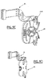
- FIGS. 9A to 9D the module according to the invention is described in relative positions of the arm 19 and of the different cassette 23, made possible by the characteristics of these elements.
- the cassette 23 can be positioned above the arm 19, with its bottom on the same side as the bottom of the arm ( Figure 9A) or with its bottom on the opposite side from that of the arm ( Figure 9B). Its position is stable by pressing on the arm 19.
- the cassette 23 can be positioned below the arm 19, with its bottom on the same side as the bottom of the arm ( Figure 9C) or with its bottom on the opposite side from that of the arm ( Figure 9D). Its position is then stable thanks to an arrangement to snap the cassette onto the arm (not described above) produced by a ratchet 23A carried by the cassette and snapping into an orifice arm correspondent.
- Figure 10 is an overview of the preferred method of assembly of several modules and corresponds to an assembly method of the type of that shown in Figure 5 without representation of the elements of the distributor.
Landscapes
- Physics & Mathematics (AREA)
- General Physics & Mathematics (AREA)
- Optics & Photonics (AREA)
- Light Guides In General And Applications Therefor (AREA)
- Mechanical Coupling Of Light Guides (AREA)
Abstract
Selon l'invention, ladite cassette de lovage (23) est montée sur ledit bras (19) par l'intermédiaire d'une articulation.
Description
Si le nombre de baies est plus grand que deux, il est bien entendu possible de prévoir le passage des jarretières, soit au niveau d'une zone de brassage unique entre deux des baies, soit dans des zones distribuées chacune entre deux baies, si besoin est. Il doit également être compris que dans un répartiteur constitué d'une seule baie, il est possible de prévoir une zone de brassage permettant une circulation verticale des jarretières sur au moins un des côtés de la baie.
Claims (9)
- Module de distribution et de connexion (19, 23) de fibres optiques destiné à un répartiteur optique, la première extrémité de chaque fibre étant raccordée à une embase de connexion (6) et la seconde extrémité de chaque fibre étant reliée à un câble optique de transmission ou de distribution, module comportant un bras de guidage (19) de chaque fibre fixé par sa première extrémité sur un support (13B) de rangée d'embases de connexion (6) et relié par sa seconde extrémité à une cassette de lovage (23) de chaque fibre, caractérisé en ce que ladite cassette de lovage (23) est montée sur ledit bras (19) par l'intermédiaire d'une articulation.
- Module selon la revendication 1, caractérisé en ce que ledit bras (19) est fixe.
- Module selon la revendication 1 ou 2, caractérisé en ce que ledit bras (19) comporte, à sa seconde extrémité, un élément d'articulation (26) pour ladite cassette (23) constitué d'un pivot horizontal.
- Module selon la revendication 3, caractérisé en ce que ce pivot fait saillie latéralement d'un prolongement plan du fond d'un canal en U que forme le bras.
- Module selon l'une des revendications précédentes, caractérisé en ce que ladite cassette (23) comporte un élément d'articulation (28, 28'), formé d'une portée pour pivot, complémentaire de l'élément d'articulation (26) porté par le bras de support (19)
- Module selon la revendication 5, caractérisé en ce que l'élément d'articulation complémentaire porté par la dite cassette est entouré par deux conduits (29, 30 ou 29', 30') pour fibre, un premier de ces conduits (30 ou 30'), réalisé vers l'intérieur de la cassette par rapport à l'autre et à l'élément d'articulation complémentaire (28 ou 28') qu'il jouxte, étant destiné au passage de chaque fibre vers le bras portant la cassette, lorsque celle-ci est portée par l'intermédiaire de l'élément d'articulation complémentaire que ce premier conduit jouxte, le second de ces conduits (29 ou 29'), réalisé vers l'extérieur de la cassette par rapport au premier conduit et à l'élément d'articulation complémentaire qu'il jouxte, étant destiné au passage des fibres émanant de câbles de transmission ou de distribution qui sont raccordées à la cassette.
- Module selon la revendication 5 ou 6, caractérisé en ce que ladite cassette (23) comporte deux éléments d'articulation (28, 28'), symétriquement disposés par rapport au plan transversal au niveau des extrémités d'un des grands côtés du boítier que forme la cassette s'articulant par l'un ou l'autre de ces deux éléments d'articulation complémentaires (28 ou 28') suivant le montage prévu pour le bras (19 ou 19').
- Module selon l'une des revendications précédentes, caractérisé en ce que ledit bras est doublement coudé en sens inverse dans deux dimensions et de préférence à mi-longueur.
- Module selon l'une des revendications précédentes, caractérisé en ce que ladite cassette de lovage (23) porte un cliquet d'encliquetage (23A) destiné à coopérer avec un orifice correspondant du bras (19).
Applications Claiming Priority (4)
| Application Number | Priority Date | Filing Date | Title |
|---|---|---|---|
| FR0114958A FR2832225B1 (fr) | 2001-11-13 | 2001-11-13 | Repartiteur optique a haute densite et procede pour le jarretierage d'un tel repartiteur |
| FR0114958 | 2001-11-13 | ||
| FR0201732A FR2832226B1 (fr) | 2001-11-13 | 2002-02-07 | Module de distribution et de connexion de fibres optiques destine a un repartiteur optique |
| FR0201732 | 2002-02-07 |
Publications (3)
| Publication Number | Publication Date |
|---|---|
| EP1315009A2 true EP1315009A2 (fr) | 2003-05-28 |
| EP1315009A3 EP1315009A3 (fr) | 2003-12-17 |
| EP1315009B1 EP1315009B1 (fr) | 2007-02-14 |
Family
ID=26213268
Family Applications (1)
| Application Number | Title | Priority Date | Filing Date |
|---|---|---|---|
| EP02292794A Expired - Lifetime EP1315009B1 (fr) | 2001-11-13 | 2002-11-08 | Module de distribution et de connexion de fibres optiques destiné à un répartiteur optique |
Country Status (8)
| Country | Link |
|---|---|
| US (1) | US6865330B2 (fr) |
| EP (1) | EP1315009B1 (fr) |
| JP (1) | JP2003222730A (fr) |
| CN (1) | CN1304863C (fr) |
| AT (1) | ATE354112T1 (fr) |
| DE (1) | DE60218108T2 (fr) |
| ES (1) | ES2280498T3 (fr) |
| FR (1) | FR2832226B1 (fr) |
Cited By (1)
| Publication number | Priority date | Publication date | Assignee | Title |
|---|---|---|---|---|
| WO2004049029A1 (fr) * | 2002-11-22 | 2004-06-10 | Krone Gmbh | Systeme de distribution de fibres optiques et procede associe |
Families Citing this family (51)
| Publication number | Priority date | Publication date | Assignee | Title |
|---|---|---|---|---|
| CN101517446B (zh) * | 2006-09-13 | 2011-04-13 | 3M创新有限公司 | 带接头托盘的光纤线路管理系统 |
| CN101937120B (zh) * | 2009-06-30 | 2012-05-09 | 昆山市大唐通讯设备有限公司 | 光纤非热融接续盒 |
| US9229172B2 (en) | 2011-09-12 | 2016-01-05 | Commscope Technologies Llc | Bend-limited flexible optical interconnect device for signal distribution |
| US9417418B2 (en) | 2011-09-12 | 2016-08-16 | Commscope Technologies Llc | Flexible lensed optical interconnect device for signal distribution |
| US9002166B2 (en) | 2011-10-07 | 2015-04-07 | Adc Telecommunications, Inc. | Slidable fiber optic connection module with cable slack management |
| US9170391B2 (en) | 2011-10-07 | 2015-10-27 | Adc Telecommunications, Inc. | Slidable fiber optic connection module with cable slack management |
| CN108594384B (zh) | 2011-10-07 | 2022-03-08 | Adc电信公司 | 光纤盒、系统和方法 |
| CN103975264B (zh) | 2011-10-07 | 2015-09-16 | Adc电信公司 | 带有缆线松弛管理的可滑动光纤连接模块 |
| US9075203B2 (en) | 2012-01-17 | 2015-07-07 | Adc Telecommunications, Inc. | Fiber optic adapter block |
| US9195021B2 (en) | 2012-09-21 | 2015-11-24 | Adc Telecommunications, Inc. | Slidable fiber optic connection module with cable slack management |
| US10082636B2 (en) | 2012-09-21 | 2018-09-25 | Commscope Technologies Llc | Slidable fiber optic connection module with cable slack management |
| IN2015DN02865A (fr) | 2012-09-28 | 2015-09-11 | Tyco Electronics Ltd Uk | |
| IN2015DN02869A (fr) | 2012-09-28 | 2015-09-11 | Tyco Electronics Ltd Uk | |
| US9146374B2 (en) | 2012-09-28 | 2015-09-29 | Adc Telecommunications, Inc. | Rapid deployment packaging for optical fiber |
| US9223094B2 (en) | 2012-10-05 | 2015-12-29 | Tyco Electronics Nederland Bv | Flexible optical circuit, cassettes, and methods |
| US9568699B2 (en) | 2013-01-29 | 2017-02-14 | CommScope Connectivity Belgium BVBA | Optical fiber distribution system |
| US9128262B2 (en) | 2013-02-05 | 2015-09-08 | Adc Telecommunications, Inc. | Slidable telecommunications tray with cable slack management |
| EP2962148A4 (fr) | 2013-02-27 | 2016-10-19 | Adc Telecommunications Inc | Module de connexion de fibre optique coulissant avec gestion de mou de câble |
| US9435975B2 (en) | 2013-03-15 | 2016-09-06 | Commscope Technologies Llc | Modular high density telecommunications frame and chassis system |
| US9541726B2 (en) | 2013-04-24 | 2017-01-10 | Adc Czech Republic, S.R.O. | Optical fiber distribution system |
| AP2015008823A0 (en) | 2013-04-24 | 2015-10-31 | Tyco Electronics Raychem Bvba | Universal mounting mechanism for mounting a telecommunications chassis to a telecommunications fixture |
| CN109725393B (zh) | 2014-01-28 | 2021-09-24 | Adc电信公司 | 带有缆线松弛管理的可滑动光纤连接模块 |
| US9494758B2 (en) | 2014-04-03 | 2016-11-15 | Commscope Technologies Llc | Fiber optic distribution system |
| WO2016094331A1 (fr) | 2014-12-10 | 2016-06-16 | Commscope Technologies Llc | Module de gestion de mou de câble à fibres optiques |
| EP3278159B1 (fr) | 2015-04-03 | 2023-08-16 | CommScope Connectivity Belgium BVBA | Éléments de distribution de télécommunication |
| US11674345B2 (en) | 2016-04-19 | 2023-06-13 | Commscope, Inc. Of North Carolina | Door assembly for a telecommunications chassis with a combination hinge structure |
| US10539757B2 (en) | 2016-04-19 | 2020-01-21 | Commscope, Inc. Of North Carolina | Telecommunications chassis with slidable trays |
| WO2018046677A1 (fr) | 2016-09-08 | 2018-03-15 | CommScope Connectivity Belgium BVBA | Éléments de répartition de télécommunications |
| WO2018071341A2 (fr) * | 2016-10-10 | 2018-04-19 | Telescent Inc. | Système de répartiteurs de fibres robotiques à grande échelle utilisant une réservation de lignes de jonction multifibre |
| US20220132229A1 (en) * | 2016-10-10 | 2022-04-28 | Telescent, Inc. | Incrementally scalable, two-tier system of robotic, fiber optic interconnect units enabling any-to-any connectivity |
| US11215767B2 (en) | 2017-06-07 | 2022-01-04 | Commscope Technologies Llc | Fiber optic adapter and cassette |
| EP3692404A4 (fr) | 2017-10-02 | 2021-06-16 | Commscope Technologies LLC | Circuit optique et procédé de préparation |
| WO2019079419A1 (fr) | 2017-10-18 | 2019-04-25 | Commscope Technologies Llc | Cassettes de connexion de fibres optiques |
| WO2019169148A1 (fr) | 2018-02-28 | 2019-09-06 | Commscope Technologies Llc | Ensemble d'emballage pour équipement de télécommunications |
| WO2019204317A1 (fr) | 2018-04-16 | 2019-10-24 | Commscope Technologies Llc | Structure d'adaptateur |
| US11635578B2 (en) | 2018-04-17 | 2023-04-25 | CommScope Connectivity Belgium BVBA | Telecommunications distribution elements |
| EP3844973B1 (fr) | 2018-08-31 | 2024-11-06 | CommScope Connectivity Belgium BVBA | Ensembles cadre pour éléments de distribution de fibres optiques |
| WO2020043914A1 (fr) | 2018-08-31 | 2020-03-05 | CommScope Connectivity Belgium BVBA | Ensembles cadres pour éléments de distribution de fibres optiques |
| EP3845044B1 (fr) | 2018-08-31 | 2023-02-15 | CommScope Connectivity Belgium BVBA | Ensembles bâtis d'éléments de distribution de fibre optique |
| MX2021002249A (es) | 2018-08-31 | 2021-07-15 | CommScope Connectivity Belgium BVBA | Unidades de marco para elementos de distribucion de fibra optica. |
| EP4776045A2 (fr) | 2018-08-31 | 2026-07-15 | CommScope Connectivity Belgium BV | Ensembles cadre pour éléments de distribution de fibres optiques |
| ES3041619T3 (en) | 2018-10-23 | 2025-11-13 | CommScope Connectivity Belgium BVBA | Frame assemblies for optical fiber distribution elements |
| EP3657068A1 (fr) * | 2018-11-22 | 2020-05-27 | ZKW Group GmbH | Dispositif de production et d'émission de lumière |
| WO2020152347A1 (fr) | 2019-01-25 | 2020-07-30 | CommScope Connectivity Belgium BVBA | Ensembles cadre pour éléments de distribution de fibre optique |
| DK4094107T3 (da) | 2020-01-22 | 2025-09-22 | CommScope Connectivity Belgium BVBA | Kabeltermineringsenheder til optiske fiberfordelingselementer |
| WO2021148552A1 (fr) | 2020-01-24 | 2021-07-29 | CommScope Connectivity Belgium BVBA | Éléments de distribution de télécommunications |
| US12468106B2 (en) | 2020-02-07 | 2025-11-11 | CommScope Connectivity Belgium BVBA | Telecommunications module arrangements |
| EP4127799B1 (fr) | 2020-03-31 | 2025-11-19 | CommScope Technologies LLC | Systèmes de gestion de câbles à fibres optiques |
| CN113534377B (zh) * | 2021-06-26 | 2022-09-16 | 华为技术有限公司 | 光纤配线设备、光纤调度方法和系统 |
| CN113534374B (zh) * | 2021-06-26 | 2022-06-14 | 华为技术有限公司 | 光纤配线设备和光纤调度系统 |
| CN113866902B (zh) * | 2021-09-30 | 2023-01-31 | 烽火通信科技股份有限公司 | 一种实现自动光纤配线的装置及其控制方法 |
Family Cites Families (24)
| Publication number | Priority date | Publication date | Assignee | Title |
|---|---|---|---|---|
| US4052460A (en) | 1976-01-20 | 1977-10-04 | Bayer Aktiengesellschaft | Production of 3,3-dimethyl-2-oxo-butyric acid salt |
| FR2531544B1 (fr) * | 1982-08-04 | 1985-01-25 | Cit Alcatel | Tete de cable optique |
| US4858303A (en) * | 1983-08-12 | 1989-08-22 | General Electric Company | Method of assembling a dynamoelectric machine |
| GB2198549A (en) * | 1986-12-12 | 1988-06-15 | Telephone Cables Ltd | Optical fibre distribution frame |
| US4898448A (en) * | 1988-05-02 | 1990-02-06 | Gte Products Corporation | Fiber distribution panel |
| US5100221A (en) * | 1990-01-22 | 1992-03-31 | Porta Systems Corp. | Optical fiber cable distribution frame and support |
| US5353367A (en) * | 1993-11-29 | 1994-10-04 | Northern Telecom Limited | Distribution frame and optical connector holder combination |
| TW232757B (en) | 1994-01-21 | 1994-10-21 | Adc Telecommunications Inc | High-density fiber distribution frame |
| US5402515A (en) * | 1994-03-01 | 1995-03-28 | Minnesota Mining And Manufacturing Company | Fiber distribution frame system, cabinets, trays and fiber optic connector couplings |
| US5461693A (en) | 1994-07-14 | 1995-10-24 | At&T Ipm Corp. | Optical fiber distribution frame with fiber testing |
| DE4442823A1 (de) * | 1994-12-01 | 1996-06-05 | Siemens Ag | Kassettenmodul für Lichtwellenleiter |
| JP3216692B2 (ja) | 1995-01-23 | 2001-10-09 | 日本電信電話株式会社 | 光ファイバ接続替え装置及び方法 |
| US5631993A (en) * | 1995-04-20 | 1997-05-20 | Preformed Line Products Company | Optical fiber splice case |
| JP3148609B2 (ja) | 1995-12-08 | 2001-03-19 | 株式会社フジクラ | 光配線盤 |
| US5828807A (en) * | 1996-04-30 | 1998-10-27 | Next Level Communications | Optical network unit (ONU) mechanical enclosure |
| JPH09304631A (ja) * | 1996-05-14 | 1997-11-28 | Japan Riicom:Kk | ケーブル接続用クロージャ |
| US5689606A (en) * | 1996-06-03 | 1997-11-18 | Scientific-Atlanta, Inc. | Fiber routing and retention assembly with modular fiber connector support |
| JP3730337B2 (ja) * | 1996-10-16 | 2006-01-05 | 株式会社ジャパンリーコム | ケーブル接続用クロージャ |
| GB2325531A (en) * | 1997-05-19 | 1998-11-25 | Pirelli General Plc | Optical fibre connector organiser |
| FR2764995B1 (fr) | 1997-06-20 | 1999-07-23 | France Telecom | Repartiteur a haute densite et grande capacite, notamment pour fibres optiques |
| US5987203A (en) | 1997-10-09 | 1999-11-16 | Lucent Technologies Inc. | Distribution module for optical couplings |
| US5946440A (en) * | 1997-11-17 | 1999-08-31 | Adc Telecommunications, Inc. | Optical fiber cable management device |
| US6041155A (en) * | 1997-12-10 | 2000-03-21 | Lucent Technologies Inc. | Universal dust cover |
| FR2789497B1 (fr) * | 1999-02-04 | 2002-06-14 | Cit Alcatel | Organiseur de fibres optiques |
-
2002
- 2002-02-07 FR FR0201732A patent/FR2832226B1/fr not_active Expired - Fee Related
- 2002-11-07 US US10/290,055 patent/US6865330B2/en not_active Expired - Fee Related
- 2002-11-08 DE DE60218108T patent/DE60218108T2/de not_active Expired - Lifetime
- 2002-11-08 ES ES02292794T patent/ES2280498T3/es not_active Expired - Lifetime
- 2002-11-08 AT AT02292794T patent/ATE354112T1/de not_active IP Right Cessation
- 2002-11-08 EP EP02292794A patent/EP1315009B1/fr not_active Expired - Lifetime
- 2002-11-13 JP JP2002329540A patent/JP2003222730A/ja active Pending
- 2002-11-13 CN CNB021606102A patent/CN1304863C/zh not_active Expired - Fee Related
Cited By (2)
| Publication number | Priority date | Publication date | Assignee | Title |
|---|---|---|---|---|
| WO2004049029A1 (fr) * | 2002-11-22 | 2004-06-10 | Krone Gmbh | Systeme de distribution de fibres optiques et procede associe |
| US7460757B2 (en) | 2002-11-22 | 2008-12-02 | Adc Gmbh | Distributor system and method for fibre optic cables |
Also Published As
| Publication number | Publication date |
|---|---|
| US20030128951A1 (en) | 2003-07-10 |
| ES2280498T3 (es) | 2007-09-16 |
| ATE354112T1 (de) | 2007-03-15 |
| DE60218108D1 (de) | 2007-03-29 |
| JP2003222730A (ja) | 2003-08-08 |
| FR2832226A1 (fr) | 2003-05-16 |
| CN1304863C (zh) | 2007-03-14 |
| DE60218108T2 (de) | 2007-11-22 |
| EP1315009A3 (fr) | 2003-12-17 |
| US6865330B2 (en) | 2005-03-08 |
| EP1315009B1 (fr) | 2007-02-14 |
| FR2832226B1 (fr) | 2004-10-22 |
| CN1419145A (zh) | 2003-05-21 |
Similar Documents
| Publication | Publication Date | Title |
|---|---|---|
| EP1315009B1 (fr) | Module de distribution et de connexion de fibres optiques destiné à un répartiteur optique | |
| EP0538164B1 (fr) | Tête de câbles modulaire à fibres optiques de grande capacité | |
| FR2832225A1 (fr) | Repartiteur optique a haute densite et procede pour le jarretierage d'un tel repartiteur | |
| EP0116480B1 (fr) | Boîte de raccordement et de brassage pour fibres optiques | |
| EP0464570B1 (fr) | Dispositif modulaire pour le stockage de réserves de support de transmission sur des liaisons, notamment à fibre optique | |
| EP0397587B1 (fr) | Module et boîtier de raccordement de câbles à fibres optiques | |
| JP4099232B2 (ja) | 光ファイバオーガナイザ | |
| EP0348278A1 (fr) | Module de répartition et raccordement de fibres optiques | |
| EP0744640B1 (fr) | Boîtier de raccordement de fibre optique | |
| EP0550327B1 (fr) | Dispositif de soutien et de guidage de câbles de transmission de signaux électriques ou lumineux | |
| EP0146478A2 (fr) | Dispositif de raccordement de câbles, notamment à fibres optiques | |
| FR2531576A1 (fr) | Bati de raccordement et d'interface opto-electronique | |
| EP0226805A1 (fr) | Chassis de tête de cables optiques | |
| EP0479226A1 (fr) | Cassette de raccordement optique | |
| FR2836561A1 (fr) | Cassette pour le lovage et le maintien d'epissures entre conducteurs et organiseur d'une pluralite desdites cassettes | |
| EP1299759B1 (fr) | Boitier de raccordement de fibres optiques a des postes de travail, pour immeubles | |
| EP2116881A1 (fr) | Boitier de repartition de fibres optiques | |
| FR2501381A1 (fr) | Dispositif de raccordement sur chantier de deux cables de transmission par fibres optiques | |
| WO2016193483A1 (fr) | Cassette de lovage de fibre optique, appareil et procede mettant en oeuvre une telle cassette | |
| EP1054279A1 (fr) | Boítier d'accès à une ou plusieurs fibres optiques dans un câble tendu | |
| EP2068186A1 (fr) | Prise optique pour réseau de télécommunication | |
| FR2556847A1 (fr) | Dispositif de connexion semi-permanent pour fibres optiques et procede pour sa mise en oeuvre | |
| FR2581769A1 (fr) | Dispositif pour le stockage de fibres optiques | |
| EP0803753B1 (fr) | Dispositif d'aide pour l'intervention et le rangement des fibres d'un câble optique | |
| FR2743899A1 (fr) | Dispositif d'organisation de raccordements de fibres optiques |
Legal Events
| Date | Code | Title | Description |
|---|---|---|---|
| PUAI | Public reference made under article 153(3) epc to a published international application that has entered the european phase |
Free format text: ORIGINAL CODE: 0009012 |
|
| AK | Designated contracting states |
Designated state(s): AT BE BG CH CY CZ DE DK EE ES FI FR GB GR IE IT LI LU MC NL PT SE SK TR |
|
| AX | Request for extension of the european patent |
Extension state: AL LT LV MK RO SI |
|
| PUAL | Search report despatched |
Free format text: ORIGINAL CODE: 0009013 |
|
| AK | Designated contracting states |
Kind code of ref document: A3 Designated state(s): AT BE BG CH CY CZ DE DK EE ES FI FR GB GR IE IT LI LU MC NL PT SE SK TR |
|
| AX | Request for extension of the european patent |
Extension state: AL LT LV MK RO SI |
|
| 17P | Request for examination filed |
Effective date: 20040617 |
|
| AKX | Designation fees paid |
Designated state(s): AT BE BG CH CY CZ DE DK EE ES FI FR GB GR IE IT LI LU MC NL PT SE SK TR |
|
| AXX | Extension fees paid |
Extension state: SI Payment date: 20040617 Extension state: RO Payment date: 20040617 Extension state: LT Payment date: 20040617 Extension state: LV Payment date: 20040617 Extension state: AL Payment date: 20040617 Extension state: MK Payment date: 20040617 |
|
| GRAC | Information related to communication of intention to grant a patent modified |
Free format text: ORIGINAL CODE: EPIDOSCIGR1 |
|
| GRAP | Despatch of communication of intention to grant a patent |
Free format text: ORIGINAL CODE: EPIDOSNIGR1 |
|
| GRAS | Grant fee paid |
Free format text: ORIGINAL CODE: EPIDOSNIGR3 |
|
| GRAA | (expected) grant |
Free format text: ORIGINAL CODE: 0009210 |
|
| AK | Designated contracting states |
Kind code of ref document: B1 Designated state(s): AT BE BG CH CY CZ DE DK EE ES FI FR GB GR IE IT LI LU MC NL PT SE SK TR |
|
| AX | Request for extension of the european patent |
Extension state: AL LT LV MK RO SI |
|
| PG25 | Lapsed in a contracting state [announced via postgrant information from national office to epo] |
Ref country code: AT Free format text: LAPSE BECAUSE OF FAILURE TO SUBMIT A TRANSLATION OF THE DESCRIPTION OR TO PAY THE FEE WITHIN THE PRESCRIBED TIME-LIMIT Effective date: 20070214 Ref country code: IE Free format text: LAPSE BECAUSE OF FAILURE TO SUBMIT A TRANSLATION OF THE DESCRIPTION OR TO PAY THE FEE WITHIN THE PRESCRIBED TIME-LIMIT Effective date: 20070214 Ref country code: DK Free format text: LAPSE BECAUSE OF FAILURE TO SUBMIT A TRANSLATION OF THE DESCRIPTION OR TO PAY THE FEE WITHIN THE PRESCRIBED TIME-LIMIT Effective date: 20070214 Ref country code: FI Free format text: LAPSE BECAUSE OF FAILURE TO SUBMIT A TRANSLATION OF THE DESCRIPTION OR TO PAY THE FEE WITHIN THE PRESCRIBED TIME-LIMIT Effective date: 20070214 |
|
| REG | Reference to a national code |
Ref country code: GB Ref legal event code: FG4D Free format text: NOT ENGLISH |
|
| REG | Reference to a national code |
Ref country code: CH Ref legal event code: EP |
|
| REF | Corresponds to: |
Ref document number: 60218108 Country of ref document: DE Date of ref document: 20070329 Kind code of ref document: P |
|
| REG | Reference to a national code |
Ref country code: IE Ref legal event code: FG4D Free format text: LANGUAGE OF EP DOCUMENT: FRENCH |
|
| GBT | Gb: translation of ep patent filed (gb section 77(6)(a)/1977) |
Effective date: 20070410 |
|
| PG25 | Lapsed in a contracting state [announced via postgrant information from national office to epo] |
Ref country code: SE Free format text: LAPSE BECAUSE OF FAILURE TO SUBMIT A TRANSLATION OF THE DESCRIPTION OR TO PAY THE FEE WITHIN THE PRESCRIBED TIME-LIMIT Effective date: 20070514 |
|
| PG25 | Lapsed in a contracting state [announced via postgrant information from national office to epo] |
Ref country code: BG Free format text: LAPSE BECAUSE OF THE APPLICANT RENOUNCES Effective date: 20070515 |
|
| PG25 | Lapsed in a contracting state [announced via postgrant information from national office to epo] |
Ref country code: PT Free format text: LAPSE BECAUSE OF FAILURE TO SUBMIT A TRANSLATION OF THE DESCRIPTION OR TO PAY THE FEE WITHIN THE PRESCRIBED TIME-LIMIT Effective date: 20070716 |
|
| LTIE | Lt: invalidation of european patent or patent extension |
Effective date: 20070214 |
|
| REG | Reference to a national code |
Ref country code: ES Ref legal event code: FG2A Ref document number: 2280498 Country of ref document: ES Kind code of ref document: T3 |
|
| REG | Reference to a national code |
Ref country code: IE Ref legal event code: FD4D |
|
| PG25 | Lapsed in a contracting state [announced via postgrant information from national office to epo] |
Ref country code: SK Free format text: LAPSE BECAUSE OF FAILURE TO SUBMIT A TRANSLATION OF THE DESCRIPTION OR TO PAY THE FEE WITHIN THE PRESCRIBED TIME-LIMIT Effective date: 20070214 |
|
| PLBE | No opposition filed within time limit |
Free format text: ORIGINAL CODE: 0009261 |
|
| STAA | Information on the status of an ep patent application or granted ep patent |
Free format text: STATUS: NO OPPOSITION FILED WITHIN TIME LIMIT |
|
| PG25 | Lapsed in a contracting state [announced via postgrant information from national office to epo] |
Ref country code: CZ Free format text: LAPSE BECAUSE OF FAILURE TO SUBMIT A TRANSLATION OF THE DESCRIPTION OR TO PAY THE FEE WITHIN THE PRESCRIBED TIME-LIMIT Effective date: 20070214 |
|
| 26N | No opposition filed |
Effective date: 20071115 |
|
| PGFP | Annual fee paid to national office [announced via postgrant information from national office to epo] |
Ref country code: LU Payment date: 20071119 Year of fee payment: 6 |
|
| PG25 | Lapsed in a contracting state [announced via postgrant information from national office to epo] |
Ref country code: IT Free format text: LAPSE BECAUSE OF FAILURE TO SUBMIT A TRANSLATION OF THE DESCRIPTION OR TO PAY THE FEE WITHIN THE PRESCRIBED TIME-LIMIT Effective date: 20070214 Ref country code: GR Free format text: LAPSE BECAUSE OF FAILURE TO SUBMIT A TRANSLATION OF THE DESCRIPTION OR TO PAY THE FEE WITHIN THE PRESCRIBED TIME-LIMIT Effective date: 20070515 |
|
| BERE | Be: lapsed |
Owner name: NEXANS Effective date: 20071130 |
|
| PG25 | Lapsed in a contracting state [announced via postgrant information from national office to epo] |
Ref country code: MC Free format text: LAPSE BECAUSE OF NON-PAYMENT OF DUE FEES Effective date: 20071130 |
|
| PG25 | Lapsed in a contracting state [announced via postgrant information from national office to epo] |
Ref country code: LI Free format text: LAPSE BECAUSE OF NON-PAYMENT OF DUE FEES Effective date: 20071130 Ref country code: CH Free format text: LAPSE BECAUSE OF NON-PAYMENT OF DUE FEES Effective date: 20071130 |
|
| REG | Reference to a national code |
Ref country code: CH Ref legal event code: PL |
|
| PG25 | Lapsed in a contracting state [announced via postgrant information from national office to epo] |
Ref country code: BE Free format text: LAPSE BECAUSE OF NON-PAYMENT OF DUE FEES Effective date: 20071130 |
|
| PG25 | Lapsed in a contracting state [announced via postgrant information from national office to epo] |
Ref country code: EE Free format text: LAPSE BECAUSE OF FAILURE TO SUBMIT A TRANSLATION OF THE DESCRIPTION OR TO PAY THE FEE WITHIN THE PRESCRIBED TIME-LIMIT Effective date: 20070214 |
|
| PG25 | Lapsed in a contracting state [announced via postgrant information from national office to epo] |
Ref country code: CY Free format text: LAPSE BECAUSE OF FAILURE TO SUBMIT A TRANSLATION OF THE DESCRIPTION OR TO PAY THE FEE WITHIN THE PRESCRIBED TIME-LIMIT Effective date: 20070214 |
|
| PG25 | Lapsed in a contracting state [announced via postgrant information from national office to epo] |
Ref country code: TR Free format text: LAPSE BECAUSE OF FAILURE TO SUBMIT A TRANSLATION OF THE DESCRIPTION OR TO PAY THE FEE WITHIN THE PRESCRIBED TIME-LIMIT Effective date: 20070214 |
|
| PGFP | Annual fee paid to national office [announced via postgrant information from national office to epo] |
Ref country code: DE Payment date: 20091120 Year of fee payment: 8 Ref country code: ES Payment date: 20091123 Year of fee payment: 8 |
|
| PGFP | Annual fee paid to national office [announced via postgrant information from national office to epo] |
Ref country code: NL Payment date: 20091112 Year of fee payment: 8 |
|
| PGFP | Annual fee paid to national office [announced via postgrant information from national office to epo] |
Ref country code: FR Payment date: 20091201 Year of fee payment: 8 Ref country code: GB Payment date: 20091119 Year of fee payment: 8 |
|
| PG25 | Lapsed in a contracting state [announced via postgrant information from national office to epo] |
Ref country code: LU Free format text: LAPSE BECAUSE OF NON-PAYMENT OF DUE FEES Effective date: 20081108 |
|
| REG | Reference to a national code |
Ref country code: NL Ref legal event code: V1 Effective date: 20110601 |
|
| GBPC | Gb: european patent ceased through non-payment of renewal fee |
Effective date: 20101108 |
|
| REG | Reference to a national code |
Ref country code: FR Ref legal event code: ST Effective date: 20110801 |
|
| PG25 | Lapsed in a contracting state [announced via postgrant information from national office to epo] |
Ref country code: NL Free format text: LAPSE BECAUSE OF NON-PAYMENT OF DUE FEES Effective date: 20110601 |
|
| REG | Reference to a national code |
Ref country code: DE Ref legal event code: R119 Ref document number: 60218108 Country of ref document: DE Effective date: 20110601 Ref country code: DE Ref legal event code: R119 Ref document number: 60218108 Country of ref document: DE Effective date: 20110531 |
|
| PG25 | Lapsed in a contracting state [announced via postgrant information from national office to epo] |
Ref country code: FR Free format text: LAPSE BECAUSE OF NON-PAYMENT OF DUE FEES Effective date: 20101130 |
|
| PG25 | Lapsed in a contracting state [announced via postgrant information from national office to epo] |
Ref country code: GB Free format text: LAPSE BECAUSE OF NON-PAYMENT OF DUE FEES Effective date: 20101108 |
|
| REG | Reference to a national code |
Ref country code: ES Ref legal event code: FD2A Effective date: 20120110 |
|
| PG25 | Lapsed in a contracting state [announced via postgrant information from national office to epo] |
Ref country code: ES Free format text: LAPSE BECAUSE OF NON-PAYMENT OF DUE FEES Effective date: 20101109 |
|
| PG25 | Lapsed in a contracting state [announced via postgrant information from national office to epo] |
Ref country code: DE Free format text: LAPSE BECAUSE OF NON-PAYMENT OF DUE FEES Effective date: 20110531 |