US5987203A - Distribution module for optical couplings - Google Patents
Distribution module for optical couplings Download PDFInfo
- Publication number
- US5987203A US5987203A US08/947,598 US94759897A US5987203A US 5987203 A US5987203 A US 5987203A US 94759897 A US94759897 A US 94759897A US 5987203 A US5987203 A US 5987203A
- Authority
- US
- United States
- Prior art keywords
- cable
- coupling
- housing
- panel
- distribution module
- Prior art date
- Legal status (The legal status is an assumption and is not a legal conclusion. Google has not performed a legal analysis and makes no representation as to the accuracy of the status listed.)
- Expired - Lifetime
Links
- 230000008878 coupling Effects 0.000 title claims abstract description 182
- 238000010168 coupling process Methods 0.000 title claims abstract description 182
- 238000005859 coupling reaction Methods 0.000 title claims abstract description 182
- 238000009826 distribution Methods 0.000 title claims abstract description 98
- 230000003287 optical effect Effects 0.000 title claims abstract description 45
- 238000002372 labelling Methods 0.000 claims description 10
- 230000005540 biological transmission Effects 0.000 claims description 8
- 230000000717 retained effect Effects 0.000 claims description 6
- 230000000295 complement effect Effects 0.000 claims description 4
- 230000004888 barrier function Effects 0.000 claims 1
- 230000037431 insertion Effects 0.000 claims 1
- 238000003780 insertion Methods 0.000 claims 1
- 239000000835 fiber Substances 0.000 description 30
- 239000013307 optical fiber Substances 0.000 description 10
- 238000009434 installation Methods 0.000 description 8
- 230000008901 benefit Effects 0.000 description 7
- 238000004519 manufacturing process Methods 0.000 description 7
- 238000013461 design Methods 0.000 description 5
- 238000012423 maintenance Methods 0.000 description 5
- 230000007246 mechanism Effects 0.000 description 5
- 238000004140 cleaning Methods 0.000 description 4
- 238000000034 method Methods 0.000 description 4
- 238000012986 modification Methods 0.000 description 4
- 230000004048 modification Effects 0.000 description 4
- 230000008569 process Effects 0.000 description 4
- 239000000463 material Substances 0.000 description 3
- 238000004891 communication Methods 0.000 description 2
- 230000000994 depressogenic effect Effects 0.000 description 2
- 230000006870 function Effects 0.000 description 2
- 239000004800 polyvinyl chloride Substances 0.000 description 2
- 230000009467 reduction Effects 0.000 description 2
- NIXOWILDQLNWCW-UHFFFAOYSA-M Acrylate Chemical compound [O-]C(=O)C=C NIXOWILDQLNWCW-UHFFFAOYSA-M 0.000 description 1
- RYGMFSIKBFXOCR-UHFFFAOYSA-N Copper Chemical compound [Cu] RYGMFSIKBFXOCR-UHFFFAOYSA-N 0.000 description 1
- 238000013459 approach Methods 0.000 description 1
- 239000004760 aramid Substances 0.000 description 1
- 229920003235 aromatic polyamide Polymers 0.000 description 1
- 238000005253 cladding Methods 0.000 description 1
- 239000011248 coating agent Substances 0.000 description 1
- 238000000576 coating method Methods 0.000 description 1
- 229910052802 copper Inorganic materials 0.000 description 1
- 239000010949 copper Substances 0.000 description 1
- 210000005069 ears Anatomy 0.000 description 1
- 230000000694 effects Effects 0.000 description 1
- 238000005516 engineering process Methods 0.000 description 1
- 239000002657 fibrous material Substances 0.000 description 1
- 230000010354 integration Effects 0.000 description 1
- 239000000123 paper Substances 0.000 description 1
- 229920000915 polyvinyl chloride Polymers 0.000 description 1
- 230000001681 protective effect Effects 0.000 description 1
- 210000002105 tongue Anatomy 0.000 description 1
- 238000003466 welding Methods 0.000 description 1
Images


Classifications
-
- G—PHYSICS
- G02—OPTICS
- G02B—OPTICAL ELEMENTS, SYSTEMS OR APPARATUS
- G02B6/00—Light guides; Structural details of arrangements comprising light guides and other optical elements, e.g. couplings
- G02B6/24—Coupling light guides
- G02B6/36—Mechanical coupling means
- G02B6/38—Mechanical coupling means having fibre to fibre mating means
- G02B6/3807—Dismountable connectors, i.e. comprising plugs
- G02B6/381—Dismountable connectors, i.e. comprising plugs of the ferrule type, e.g. fibre ends embedded in ferrules, connecting a pair of fibres
- G02B6/3825—Dismountable connectors, i.e. comprising plugs of the ferrule type, e.g. fibre ends embedded in ferrules, connecting a pair of fibres with an intermediate part, e.g. adapter, receptacle, linking two plugs
-
- G—PHYSICS
- G02—OPTICS
- G02B—OPTICAL ELEMENTS, SYSTEMS OR APPARATUS
- G02B6/00—Light guides; Structural details of arrangements comprising light guides and other optical elements, e.g. couplings
- G02B6/44—Mechanical structures for providing tensile strength and external protection for fibres, e.g. optical transmission cables
- G02B6/4439—Auxiliary devices
- G02B6/444—Systems or boxes with surplus lengths
- G02B6/44528—Patch-cords; Connector arrangements in the system or in the box
-
- G—PHYSICS
- G02—OPTICS
- G02B—OPTICAL ELEMENTS, SYSTEMS OR APPARATUS
- G02B6/00—Light guides; Structural details of arrangements comprising light guides and other optical elements, e.g. couplings
- G02B6/44—Mechanical structures for providing tensile strength and external protection for fibres, e.g. optical transmission cables
- G02B6/4439—Auxiliary devices
- G02B6/444—Systems or boxes with surplus lengths
- G02B6/4453—Cassettes
- G02B6/4454—Cassettes with splices
-
- G—PHYSICS
- G02—OPTICS
- G02B—OPTICAL ELEMENTS, SYSTEMS OR APPARATUS
- G02B6/00—Light guides; Structural details of arrangements comprising light guides and other optical elements, e.g. couplings
- G02B6/24—Coupling light guides
- G02B6/36—Mechanical coupling means
- G02B6/38—Mechanical coupling means having fibre to fibre mating means
- G02B6/3807—Dismountable connectors, i.e. comprising plugs
- G02B6/3873—Connectors using guide surfaces for aligning ferrule ends, e.g. tubes, sleeves, V-grooves, rods, pins, balls
- G02B6/3874—Connectors using guide surfaces for aligning ferrule ends, e.g. tubes, sleeves, V-grooves, rods, pins, balls using tubes, sleeves to align ferrules
-
- G—PHYSICS
- G02—OPTICS
- G02B—OPTICAL ELEMENTS, SYSTEMS OR APPARATUS
- G02B6/00—Light guides; Structural details of arrangements comprising light guides and other optical elements, e.g. couplings
- G02B6/44—Mechanical structures for providing tensile strength and external protection for fibres, e.g. optical transmission cables
- G02B6/4439—Auxiliary devices
- G02B6/444—Systems or boxes with surplus lengths
- G02B6/4452—Distribution frames
- G02B6/44526—Panels or rackmounts covering a whole width of the frame or rack
-
- H—ELECTRICITY
- H01—ELECTRIC ELEMENTS
- H01R—ELECTRICALLY-CONDUCTIVE CONNECTIONS; STRUCTURAL ASSOCIATIONS OF A PLURALITY OF MUTUALLY-INSULATED ELECTRICAL CONNECTING ELEMENTS; COUPLING DEVICES; CURRENT COLLECTORS
- H01R13/00—Details of coupling devices of the kinds covered by groups H01R12/70 or H01R24/00 - H01R33/00
- H01R13/73—Means for mounting coupling parts to apparatus or structures, e.g. to a wall
- H01R13/74—Means for mounting coupling parts in openings of a panel
- H01R13/741—Means for mounting coupling parts in openings of a panel using snap fastening means
- H01R13/743—Means for mounting coupling parts in openings of a panel using snap fastening means integral with the housing
-
- H—ELECTRICITY
- H01—ELECTRIC ELEMENTS
- H01R—ELECTRICALLY-CONDUCTIVE CONNECTIONS; STRUCTURAL ASSOCIATIONS OF A PLURALITY OF MUTUALLY-INSULATED ELECTRICAL CONNECTING ELEMENTS; COUPLING DEVICES; CURRENT COLLECTORS
- H01R9/00—Structural associations of a plurality of mutually-insulated electrical connecting elements, e.g. terminal strips or terminal blocks; Terminals or binding posts mounted upon a base or in a case; Bases therefor
- H01R9/22—Bases, e.g. strip, block, panel
- H01R9/24—Terminal blocks
- H01R9/2475—Means facilitating correct wiring, e.g. marking plates, identification tags
Definitions
- the present invention relates generally to the field of optical fiber distribution systems, and more particularly to a distribution module that can be used in an electrical panel to facilitate multi-fiber connections and to integrate optical and electrical couplers onto a single panel.
- Couplings for optical fiber transmission systems are known in the art. Often times it becomes necessary to arrange a plurality of optical fiber couplings in a panel to facilitate multi-fiber connections. These panels are typically found in telecommunications closets where connections are made between cables by patching one cable connector to another. Desirably, devices for holding couplings are mounted in the panel, but the couplings themselves are not connected to incoming or outgoing fiber paths until actually needed to provide service.
- Optical couplings come in a variety of types, each having a unique interface designed to mate with an optical fiber connector of like type.
- One frequently used coupling is referred to as an ST® coupling, which is disclosed, for example, in U.S. Pat. No. 4,934,785 to Mathis et al. ST is a registered trademark of Lucent Technologies, Inc.
- Another common type of optical fiber coupling is the SC type coupling that is shown and described in U.S. Pat. No. 5,212,752 to Stephenson et al.
- Other types of optical fiber couplings include the FC type coupling and the LC type coupling.
- U.S. Pat. No. 5,274,729 to King et al. shows examples of couplings for the ST, SC and the FC types of couplings.
- coupling systems for panels used individual or duplex couplings for making connections between the fiber optic cables. These systems do have their drawbacks, however. Depending on the application, the number of couplings used in an optical cable panel may number in the hundreds or even thousands resulting in a very time consuming assembly process for the panel. With such a large number of individual or duplex coupling locations, a technician's job in making the appropriate connections can be complicated. Moreover, because optical couplings have unique physical designs, they are often relatively expensive to manufacture.
- panels have traditionally been designed to furnish either optical coupling functionality or electrical coupling functionality. This dichotomy is driven in primary part by the physical design of the panels. Electrical panels are generally designed with elongated rectangular openings for receiving electrical coupling apparatus that terminates a plurality of electrical connectors. Conversely, optical panels are generally designed with small openings that receive either a single or duplex optical coupler. It is therefore desirable to integrate both optical and electrical couplers in a single panel to make best use of space in a telecommunications closet rather than dedicating panels on an optical versus electrical basis.
- the distribution module should be designed for use in a traditional electrical panel so that both electrical and optical couplers can be integrated onto a single panel.
- the present invention is generally directed to a distribution module for use in a traditional electrical panel that provides coupling functionality for both optical and electrical connectors.
- the distribution module is comprised of a housing with a passage defined therein.
- the distribution module further includes high density, modular coupling strips, which are chosen based on the type of connectors to be coupled. These coupling strips are joined together and then secured in the passage formed in the housing. Once assembled, the distribution module is received into an opening in the panel thereby integrating both optical and electrical couplers in a single panel.
- a slack tray can be attached to the housing that spools and offers strain relief to the buffered fiber, which is particularly vulnerable when stripped of its outer jacket.
- the drum radius on which the fiber is spooled is appropriately chosen to satisfy any minimum bend radius requirements of the fiber manufacturer.
- the distribution module can be used with coupling strips in which like types of strips are interchangeable.
- the coupling strips used in the distribution module are high density, which again offers a manufacturing and assembly cost advantage over simplex and duplex optical coupling systems known heretofore.
- a second type of coupling strip arrangement can be used in which a cap coupling strip and a base coupling strip are defined.
- the cap coupling strip and the base coupling strip are designed to snap together and separate via operation of attachment clips allowing the strips to be cleaned in the field if necessary.
- a retainer can be used to mount the entire distribution module, including the slack tray, on the front side of the panel. This feature is particularly useful when access to the back side of the panel is limited or for applications that require frequent reconfiguration of the connectors.
- the distribution module housing provides an informative human interface by including both a labeling region and an icon region where a technician can insert a labeling strip or icons to identify the individual connectors.
- FIG. 1 is a perspective view of a fiber optic cable terminated by an ST connector and a fiber optic coupler.
- FIG. 2A is a perspective view illustrating the installation of distribution modules for optical couplings on an electrical cable panel according to the instant invention.
- FIG. 2B is a perspective view illustrating the installation of distribution modules for electrical couplings on an electrical cable panel according to the instant invention.
- FIG. 3A is an exploded, perspective view illustrating a distribution module using LC coupling strips.
- FIG. 3B is a cross-sectional view of a distribution module with LC coupling strips installed.
- FIG. 4A is an exploded, perspective view illustrating a distribution module using an ST coupling strip and an SC coupling strip.
- FIG. 4B is a cross-sectional view of a distribution module with an ST coupling strip and an SC coupling strip installed.
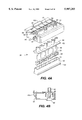
- FIG. 5A is an exploded, perspective view illustrating a distribution module using SC coupling strips.
- FIG. 5B is a cross-sectional view of a distribution module with SC coupling strips installed.
- FIG. 6A is an exploded, perspective view illustrating a distribution module using ST coupling strips.
- FIG. 6B is a cross-sectional view of a distribution module with ST coupling strips installed.
- FIG. 7A is an exploded, perspective view illustrating an alternative embodiment of ST coupling strips and a slack tray for use with the distribution module.
- FIG. 7B is a perspective view illustrating the ST coupling strips and slack tray shown in FIG. 7A installed in the distribution module.
- FIG. 8A is a perspective view illustrating the installation of the slack tray in the distribution module.
- FIG. 8B is a perspective view of the slack tray installed in the distribution module with buffered fiber spooled around the drum.
- FIG. 8C is an elevation view of the slack tray installed in the distribution module.
- FIG. 9 is a perspective view illustrating an alternative installation of the distribution module and slack tray on the front of an electrical cable panel.
- FIG. 10 is a perspective view of a distribution module illustrating the labeling strip and the icons.
- optical cable 22 includes an optical fiber 24, which is comprised of a core and a cladding surrounded by one or more layers of an acrylate coating material for protection. Additionally, optical fiber 24 may be surrounded by a layer of polyvinyl chloride (PVC) to provide what is referred to as a buffered fiber 26. Further, a sheath system is shown, illustratively comprising strength members 28 made from aramid fibrous material and an outer jacket 30 made from PVC. Together, these elements form an optical cable 22 that has excellent transmission and handling characteristics, but which cannot be joined to other optical equipment without a connecting arrangement. For that purpose, another optical connector, such as ST connector 20, and an optical coupler, such as ST coupler 31, are needed.
- another optical connector such as ST connector 20, and an optical coupler, such as ST coupler 31, are needed.
- FIG. 2A An exemplary distribution module for coupling optical connectors to one another is illustrated in FIG. 2A.
- optical or electrical cable panels such as panel 32
- panel 32 are commonly installed on a frame 34 or rack in a communications closet to provide coupling functionality for a plurality of jumper cables to facilitate multi-fiber or multi-wire connections.
- distribution modules 36a,b,c are used with electrical panel 32 to provide high density, optical coupling functionality in a single module.
- panel 32 contains a plurality of substantially rectangular openings 38 for receiving distribution modules 36a,b,c. Openings 38 can be filled with distribution modules, which can be used to provide optical coupling functionality, as shown in FIG.
- FIGS. 2A and 2B illustrate distribution modules in various stages and modes of installation for both optical coupling and electrical coupling respectively.
- distribution module 36a is fully received and secured in panel 32
- distribution module 36c with an accompanying slack tray 40, is shown in the process of being received and secured in panel 32
- distribution module 36b is shown in an alternative installation mode with both the distribution module 36b and slack tray 40 mounted on retainers 42 on the front of panel 32.
- distribution module 36 is shown to comprise a housing 44, LC coupling strips 46 and alignment sleeves 48.
- LC coupling strips are symmetrical and have a plurality of holes 50 defined therein for receiving alignment sleeves 48.
- Alignment sleeves 48 are disposed in holes 50 and are entrapped as coupling strips 46 are joined together as shown in FIG. 3B.
- Sleeves 48 are used to align the ferrules from the two connectors carrying the optical fibers to ensure that a high quality optical path is created.
- Coupling strips 46 can be secured to one another using any suitable means.
- One possible embodiment uses ultrasonic welding to secure the coupling strips together thereby providing a substantially permanent coupling module.
- Housing 44 includes a passage 51 defined by side walls (one side shown) 52 and upper and lower (not shown) walls 54.
- housing 44 includes a labeling region 56 and icon region 58 on its front face 59 for identifying connectors.
- coupling strips 46 are received in passage 51 from the back (i.e., non-face side) of housing 44.
- Upper and lower walls 54 contain a plurality of lips 60 that engage coupling strip tongues or flanges 62 to secure coupling strips 46 in passage 51.
- housing 44 For securing housing 44 to panel 32 (see FIG. 2A), housing 44 includes a pair of pins 61 (see FIGS. 3A, 4A, 5A and 6A) that rest on ears 57 contained in panel 32 alongside panel openings 38 (see FIGS. 2A and 2B). Housing 44 rotates into position on pins 61 (see, for example distribution module 36f in FIG. 2B) and is secured to the frame by latch 63u, shown best in FIG. 7A. Latch 63u is attached to housing 44 in cantilever fashion such that latch 63 is depressed as housing 44 is received in a panel opening 38. Once latch 63 clears upper panel opening edge 39u (see FIG.
- latch 63 springs upward trapping panel opening edge 39u between housing face 59 and ridges 65 (see FIGS. 7A and 10) on latch 63.
- housing 44 can be secured to panel 32 by two latches 63u and 63l that allow housing 44 to be pushed directly into panel opening 38 until latch 63u traps panel opening edge 39u and latch 63l traps panel opening edge 39l as described in the foregoing.
- Latches 63u and 63l include another desirable feature in latch tabs 67.
- distribution module can be installed relatively flush with panel 32, as illustrated by distribution module 36a in FIG. 2A, latch tabs 67 offer a convenient mechanism for grasping and operating latches 63u and 63l.
- latch tabs 67 provide usefull structure on which to apply a pulling force to effect the removal.
- coupling strips 46 are interchangeable and can thus be installed with either strip in communication with connectors on the face 59 of housing 44. Moreover, this symmetry reduces tooling costs as only one type of LC connector strip need be manufactured. Still another cost reduction feature of the instant embodiment is the placement of lips 60 on upper and lower walls 54 rather than designing a more elaborate latching mechanism as part of coupling strips 46. Inasmuch as the number of coupling strips to be manufactured is expected to exceed the number of housings, the reduction in tooling costs stemming from a simpler coupling strip design is significant.
- FIG. 4A illustrates a distribution module 36 in which two different types of coupling strips are to be intalled: an ST coupling strip 64 and an SC coupling strip 66. Because of the design of the SC connector, an SC connector latch 68 is received in each SC connector port 70. As illustrated, SC connector latches 68 are installed individually in SC coupling strip 66; however, SC connector latches 68 can be molded as a single strip to correspond with SC ports 70 to reduce manufacturing costs and to reduce assembly time.
- ST coupling strip 64 and SC coupling strip 66 are assembled substantially as described hereinbefore with respect to LC coupling strips 46 shown in FIG. 3A.
- sleeves 48 are received and retained in SC connector latch holes 72 and ST coupling strip holes 74 (see FIG. 6A) when coupling strips 64 and 66 are joined thereby entrapping sleeves 48 and SC connector latches 68 as shown in FIGS. 4A and 4B.
- the joined coupling strips are received and retained in passage 51 in the same manner as described hereinbefore with respect to FIG. 3A.
- the symmetrical nature of the coupling strips in that either ST coupling strip 64 or SC coupling strip 66 can be installed to communicate with connectors at the front face 59 of housing 44, provides great flexibility in configuring distribution module 36 to couple connectors comprising a plurality of connector types on either side of panel 32.
- FIGS. 5A and 5B show a distribution module configured in an SC duplex arrangement. That is, two SC coupling strips 66 are used along with a plurality of SC connector latches 68. Again, the SC connector latches 68 can be molded as a single strip to reduce manufacturing costs and assembly time.
- FIGS. 6A and 6B show a distribution module configured in an ST duplex arrangement.
- the ST coupling strips comprise an ST cap strip 76 and an ST base strip 78.
- ST cap strip 76 has a plurality of clips 80 disposed along its top and bottom surfaces. Each clip 80 has a tab 82 for securing cap strip 76 to base strip 78.
- cap strip 76 includes a plurality of sleeve retainers 86 for each ST port to hold the alignment sleeves 48 (see FIGS. 3 through 6).
- the mechanism by which sleeve retainers 86 hold alignment sleeves 48 is the subject of copending application entitled "SLEEVE HOUSING FOR OPTICAL COUPLING BUILDOUT," U.S. Ser. No. 08/857,841, is now patented, U.S. Pat. No. 5,838,855, by Stephenson, which is incorporated herein by reference.
- ST base strip 78 is designed with ST ports large enough to receive sleeve retainers 86 and includes a plurality of complementary holes 84 for receiving tabs 82.
- cap strip 76 and base strip 78 are pressed together thereby compressing clips 80 towards the body of cap strip 76 to allow cap strip 76 to be fully received in base strip 78.
- clips 80 being elastic and having a physical memory, spring back to their uncompressed position allowing tabs 82 to enter holes 84 securing cap strip 76 to base strip 78.
- base strip 78 is secured to housing 44 via tabs 88. As base strip 78 is positioned into passage 51 from the face 59 side of housing 44, tabs 88 are depressed as they engage edges 90 at the entrance to said passage 51.
- FIG. 7B shows distribution module 36 with ST cap strip 76 and ST base strip 78 assembled along with an accompanying slack tray 40.
- cap strip 76 can be removed from base strip 78 by simply squeezing clips 80 to disengage tabs 82 from holes 84 and pulling the two strips apart.
- This is a significant advantage for applications where it is desirable to have a cleaning capability of the internals of the coupling strips.
- the cleaning process is greatly simplified as only the connectors on cap strip 76 need be removed to clean alignment sleeves 48 and sleeve retainers 86 when cap strip 76 is removed from base strip 78.
- the connectors attached to base strip 78 can remain intact through the cleaning process. This substantially reduces the time and corresponding labor costs incurred in cleaning alignment sleeves 48 and sleeve retainers 86.
- FIGS. 8A through 8C illustrate the use of an optional slack tray 40 in conjunction with distribution module 36.
- distribution module 36 will generally be used to provide optical coupling functionality; however, as discussed in the foregoing, it is also envisioned that electrical coupling strips could be used in distribution module 36.
- Slack tray 40 would likely be unnecessary for many electrical applications, such as coaxial cable, because of electrical cable's more rugged nature. However, slack tray 40 provides important protection for fragile optical cable.
- Slack tray 40 for use with distribution module 36 will now be described.
- Slack tray 40 is comprised of a base 94 from which a drum 96 rises for spooling buffered fiber 98 as shown in FIG. 8B (see also FIG. 1 showing buffered fiber 26) and side walls 99.
- side walls 99 and drum 96 are designed with several wings 97 that guide the buffered fiber onto drum 96 and aid in retaining the buffered fiber on drum 96 once it is spooled.
- side walls 99 provide similar assistance in guiding and retaining the fiber.
- slack tray base 94 includes a plurality of apertures 102 through which cable ties can be used to secure the jacketed cable at the end opposite the distribution module to ensure that cable movement or disturbance external to slack tray 40 is not transmitted to the buffered fiber 98. Additional apertures 102 are included in base 94 within drum 96 and in the walls of drum 96 for even greater flexibility in securing the cable, either jacketed or buffered, via cable ties. Slack tray 40 further includes a spillway region 104, which will be discussed more fully hereinafter with reference to FIG. 8C.
- Distribution module housing 44 includes a pair of slots 105 for receiving bifurcated mounting tabs 106.
- a latch arm 108 runs between each bifurcated mounting tab 106 to hook over an internal lip in slots 105 to secure slack tray 40 to housing 44 as shown in FIG. 8B. It will be appreciated by those skilled in the art that a single mounting tab and slot combination could be used in the alternative to further reduce manufacturing costs.
- optical cable and buffered fiber cannot be bent at extreme angles as the protective sheathing and/or the fiber itself could be bent sufficiently to cause at least some of the light to escape the waveguide.
- cable and fiber manufacturers will specify the minimum bend radius for both jacketed and buffered fiber.
- a common standard used for jacketed fiber is that the minimum bend radius be at least ten times the cable diameter.
- the manufacturers specifications should be consulted before spooling buffered fiber onto drum 96.
- Alternative embodiments may use modular drums 96 of varying diameters to accommodate fiber types having disparate bend qualities.
- Spillway region 104 is preferably shaped to form a trough below connector boots 100. This trough provides room for a technician's fingers when manipulating connector boots 100 on the back side of distribution module 36.
- FIG. 9 illustrates an alternative mounting arrangement for distribution module housing 44 and slack tray 40 that provides front panel access to both sides of distribution module 36 (see also FIG. 2A, distribution module 36b).
- This mounting arrangement will most frequently be used as a service position that provides easy access to both sides of distribution module 36 for connector reconfiguration.
- panel 32 includes a set of three retainer mount holes 110a, 110b, 110c positioned alongside panel openings 38.
- Retainer 42 has three prongs 112a, 112b and 112c positioned to correspond to retainer mount holes 110a, 110b and 110c. Prong 112a is inserted first with prong 112b essentially acting as an alignment guide.
- Mount hole 110c is preferably shaped to be wider at the top and narrower at the bottom. This geometry allows prong 112c to slip into the wide portion of mount hole 110c but not the narrow portion. Thus, retainer 42 is locked into position by placing upward pressure on prong 112c to allow entry into the wide portion of mount hole 110c and then releasing prong 112c to allow the narrow shaft of prong 112c to spring into the narrower, bottom portion of mount hole 110c.
- slack tray 40 has a pair of shoulders 118 that rest in retainer slots 114 as seen in FIG. 9. Retainer slots 114 are preferably of sufficient width to support two slack trays positioned side by side as illustrated in FIG.
- Slack tray 40 is secured to panel 32 by hooking feet 115 (see FIGS. 8A and 8B) under upper panel edge 39u slightly compressing legs 117 such that slack tray 40 is effectively wedged between upper panel edge 39u and retainer slots 114.
- retainer arm 116 can be used to collect both in service and out of service patch cables to prevent them from becoming entangled.
- this front panel mounting arrangement allows a technician to quickly unsnap distribution module 36 from its operative position in panel 32 and place distribution module 36 into a maintenance position on retainer 42. In this maintenance position, the technician enjoys easy access to both sides of distribution module 36 substantially reducing labor time and cost for applications requiring frequent cable reconfiguration.
- the technician is provided with another option in arranging panels in a telecommunications closet as a panel can now be mounted substantially flush with a wall and the distribution modules 36 placed into operation while held on retainers 42, which is their normal maintenance position.
- distribution module housing 44 has a labeling region 56 positioned above the coupling strips that sequentially number the individual ports from left to right as shown in FIG. 10. Furthermore, labeling region 56 is recessed from housing face 59 so that a user definable labeling strip 120, made from a flexible cardboard or paper, can be inserted over labeling region and held via tabs 122.
- a second labeling mechanism is provided via icon region 58.
- icon region 58 is positioned above the coupling strips and is designed to receive individual icons identifying the nature of the connection using a particular port.
- telephone icons 124 can be used to identify a port as connecting voice or telephone service.
- a computer icon 126 can be used to identify a port as connecting data or computer service or a television icon (not shown) can be used to identify a port as connecting cable television service.
- the distribution module is highly versatile in that it can be used to couple both optical and electrical connectors through the use of high density coupling strips in the same panel.
- the distribution module can be used in a traditional electrical coupling panel thereby providing a means for integrating both electrical and optical coupling functionality in the same panel.
- Such integration allows technicians to reuse panels independent of the cable type.
- the use of high density coupling strips significantly minimizes the technician's installation and configuration time when compared to the simplex or duplex coupling systems known heretofore.
- a slack tray can be used with the distribution module to protect the exposed, buffered fiber from potential damage.
- the slack tray and distribution module can be mounted on the front of a panel, which is a highly convenient maintenance position for technicians when connectors are frequently reconfigured or when access to the rear of a panel is limited by choice or necessity.
Landscapes
- Physics & Mathematics (AREA)
- General Physics & Mathematics (AREA)
- Optics & Photonics (AREA)
- Light Guides In General And Applications Therefor (AREA)
- Mechanical Coupling Of Light Guides (AREA)
Abstract
Description
Claims (18)
Priority Applications (1)
| Application Number | Priority Date | Filing Date | Title |
|---|---|---|---|
| US08/947,598 US5987203A (en) | 1997-10-09 | 1997-10-09 | Distribution module for optical couplings |
Applications Claiming Priority (1)
| Application Number | Priority Date | Filing Date | Title |
|---|---|---|---|
| US08/947,598 US5987203A (en) | 1997-10-09 | 1997-10-09 | Distribution module for optical couplings |
Publications (1)
| Publication Number | Publication Date |
|---|---|
| US5987203A true US5987203A (en) | 1999-11-16 |
Family
ID=25486386
Family Applications (1)
| Application Number | Title | Priority Date | Filing Date |
|---|---|---|---|
| US08/947,598 Expired - Lifetime US5987203A (en) | 1997-10-09 | 1997-10-09 | Distribution module for optical couplings |
Country Status (1)
| Country | Link |
|---|---|
| US (1) | US5987203A (en) |
Cited By (82)
| Publication number | Priority date | Publication date | Assignee | Title |
|---|---|---|---|---|
| US6215064B1 (en) * | 1999-03-19 | 2001-04-10 | Siecor Operations, Llc | Electronics jumper management assembly |
| WO2001088587A1 (en) * | 2000-05-19 | 2001-11-22 | Marconi Communications Spa | Optical assembly |
| US6443627B1 (en) | 2001-01-10 | 2002-09-03 | Fitel Usa Corp. | Duplex optical connector |
| USD465455S1 (en) | 2000-12-11 | 2002-11-12 | Fiber Optic Network Solutions Corporation | Module for fiber optic equipment |
| US6478472B1 (en) | 2001-01-10 | 2002-11-12 | Fitel Usa Corp. | High-density optical connecting block |
| US20020181924A1 (en) * | 2000-12-22 | 2002-12-05 | Fiber Optic Network Solutions, Inc. | Module and housing for DWDM equipment |
| FR2832225A1 (en) * | 2001-11-13 | 2003-05-16 | Nexans | Telecommunications high density fibre optic divider/interconnection method having divider bays/ central solder zone with assembly using mounting plug/cradle/connection length adjustment then position placing second plug. |
| US6586680B1 (en) | 2000-06-02 | 2003-07-01 | Panduit Corp. | Modular bend radius control fixture |
| US20030128951A1 (en) * | 2001-11-13 | 2003-07-10 | Didier Lecomte | Optical fiber connection and distribution module intended for use in an optical distribution frame |
| US20030202767A1 (en) * | 1998-09-10 | 2003-10-30 | Glynn Thomas A. | Telecommunications fiber optic infrastructure |
| US6782206B1 (en) | 2000-11-27 | 2004-08-24 | Golden Bloom Resources, Ltd. | Multi-port optical node |
| US20040175088A1 (en) * | 2003-03-05 | 2004-09-09 | Dagley Mark R. | High density fiber optic distribution frame |
| US20050023020A1 (en) * | 2002-05-23 | 2005-02-03 | Friedrich Denter | Cover plates for ADSL-splitter positions in modular distribution frames |
| US20050163448A1 (en) * | 2004-01-27 | 2005-07-28 | Blackwell Chois A.Jr. | Multi-port optical connection terminal |
| US6980725B1 (en) * | 2002-04-30 | 2005-12-27 | Calix Networks, Inc. | Space reuse during technology upgrade in a protection area of an outdoor enclosure |
| US20070025675A1 (en) * | 2005-07-27 | 2007-02-01 | Anne Kramer | Fiber optic adapter module |
| US7400814B1 (en) * | 2007-01-13 | 2008-07-15 | Furukawa Electric North America, Inc. | Wall-mountable optical fiber and cable management apparatus |
| WO2008137894A1 (en) * | 2007-05-07 | 2008-11-13 | Adc Telecommunications, Inc. | Fiber optic enclosure with external cable spool |
| US20090074370A1 (en) * | 2007-08-06 | 2009-03-19 | Adc Telecommunications, Inc. | Fiber optic enclosure with internal cable spool |
| US20090232455A1 (en) * | 2008-03-04 | 2009-09-17 | Ponharith Pon Nhep | Multi-port adapter block |
| US7740409B2 (en) | 2007-09-19 | 2010-06-22 | Corning Cable Systems Llc | Multi-port optical connection terminal |
| US20100239210A1 (en) * | 2009-03-20 | 2010-09-23 | Wakileh George I | Multipurpose Telecommunications Modules |
| US7869682B2 (en) | 2007-09-05 | 2011-01-11 | Adc Telecommunications, Inc. | Fiber optic enclosure with tear-away spool |
| US20110044599A1 (en) * | 2009-07-21 | 2011-02-24 | Adc Telecommunications, Inc. | Rapid universal rack mount enclosure |
| US20110085774A1 (en) * | 2009-10-13 | 2011-04-14 | Leviton Manufacturing Co., Inc. | Fiber optic adapter plates with integrated fiber optic adapters |
| WO2011054743A3 (en) * | 2009-11-05 | 2011-06-30 | Weidmüller Interface GmbH & Co. KG | Mounting arrangement for electrical devices |
| US20110229102A1 (en) * | 2006-10-11 | 2011-09-22 | Panduit Corp. | Release latch for pre-terminated cassette |
| US20110235985A1 (en) * | 2010-03-26 | 2011-09-29 | Cote Monique L | Movable Adapter Panel |
| US20110268409A1 (en) * | 2010-04-30 | 2011-11-03 | Giraud William J | Apparatuses and related components and methods for expanding capacity of fiber optic housings |
| CN101221270B (en) * | 2007-01-13 | 2012-01-11 | 古河电子北美公司 | Wall-mountable optical fiber and cable management apparatus |
| CN101558341B (en) * | 2006-09-05 | 2012-08-01 | 普雷斯曼电缆和系统有限公司 | System for inserting fiber optic cables into fiber optic receivers and cable adapters for them |
| US8265447B2 (en) | 2008-09-16 | 2012-09-11 | Adc Telecommunications, Inc. | Modular fiber optic enclosure with external cable spool |
| US8382382B2 (en) | 2008-08-27 | 2013-02-26 | Adc Telecommunications, Inc. | Fiber optic adapter with integrally molded ferrule alignment structure |
| US8417074B2 (en) | 2008-11-21 | 2013-04-09 | Adc Telecommunications, Inc. | Fiber optic telecommunications module |
| DE202012104617U1 (en) * | 2012-11-28 | 2014-03-03 | Weidmüller Interface GmbH & Co. KG | Mounting a connection device |
| US8755663B2 (en) | 2010-10-28 | 2014-06-17 | Corning Cable Systems Llc | Impact resistant fiber optic enclosures and related methods |
| US8837940B2 (en) | 2010-04-14 | 2014-09-16 | Adc Telecommunications, Inc. | Methods and systems for distributing fiber optic telecommunication services to local areas and for supporting distributed antenna systems |
| US8873926B2 (en) | 2012-04-26 | 2014-10-28 | Corning Cable Systems Llc | Fiber optic enclosures employing clamping assemblies for strain relief of cables, and related assemblies and methods |
| US8953924B2 (en) | 2011-09-02 | 2015-02-10 | Corning Cable Systems Llc | Removable strain relief brackets for securing fiber optic cables and/or optical fibers to fiber optic equipment, and related assemblies and methods |
| US8958679B2 (en) | 2010-03-02 | 2015-02-17 | Tyco Electronics Services Gmbh | Fibre-optic telecommunications module |
| US8965168B2 (en) | 2010-04-30 | 2015-02-24 | Corning Cable Systems Llc | Fiber management devices for fiber optic housings, and related components and methods |
| US8989547B2 (en) | 2011-06-30 | 2015-03-24 | Corning Cable Systems Llc | Fiber optic equipment assemblies employing non-U-width-sized housings and related methods |
| US8985862B2 (en) | 2013-02-28 | 2015-03-24 | Corning Cable Systems Llc | High-density multi-fiber adapter housings |
| US8992099B2 (en) | 2010-02-04 | 2015-03-31 | Corning Cable Systems Llc | Optical interface cards, assemblies, and related methods, suited for installation and use in antenna system equipment |
| US9008485B2 (en) | 2011-05-09 | 2015-04-14 | Corning Cable Systems Llc | Attachment mechanisms employed to attach a rear housing section to a fiber optic housing, and related assemblies and methods |
| US9020320B2 (en) | 2008-08-29 | 2015-04-28 | Corning Cable Systems Llc | High density and bandwidth fiber optic apparatuses and related equipment and methods |
| US9022814B2 (en) | 2010-04-16 | 2015-05-05 | Ccs Technology, Inc. | Sealing and strain relief device for data cables |
| US9038832B2 (en) | 2011-11-30 | 2015-05-26 | Corning Cable Systems Llc | Adapter panel support assembly |
| US9042702B2 (en) | 2012-09-18 | 2015-05-26 | Corning Cable Systems Llc | Platforms and systems for fiber optic cable attachment |
| US9069151B2 (en) | 2011-10-26 | 2015-06-30 | Corning Cable Systems Llc | Composite cable breakout assembly |
| US9116324B2 (en) | 2010-10-29 | 2015-08-25 | Corning Cable Systems Llc | Stacked fiber optic modules and fiber optic equipment configured to support stacked fiber optic modules |
| US9146374B2 (en) | 2012-09-28 | 2015-09-29 | Adc Telecommunications, Inc. | Rapid deployment packaging for optical fiber |
| US9146362B2 (en) | 2012-09-21 | 2015-09-29 | Adc Telecommunications, Inc. | Insertion and removal tool for a fiber optic ferrule alignment sleeve |
| US9188760B2 (en) | 2011-12-22 | 2015-11-17 | Adc Telecommunications, Inc. | Mini rapid delivery spool |
| US9213161B2 (en) | 2010-11-05 | 2015-12-15 | Corning Cable Systems Llc | Fiber body holder and strain relief device |
| US9223094B2 (en) | 2012-10-05 | 2015-12-29 | Tyco Electronics Nederland Bv | Flexible optical circuit, cassettes, and methods |
| US9261663B2 (en) | 2010-06-18 | 2016-02-16 | Adc Communications (Shanghai) Co., Ltd. | Fiber optic distribution terminal and method of deploying fiber distribution cable |
| US20160139346A1 (en) * | 2013-07-16 | 2016-05-19 | 3M Innovative Properties Company | Telecommunication enclosure for external connection |
| US9435975B2 (en) | 2013-03-15 | 2016-09-06 | Commscope Technologies Llc | Modular high density telecommunications frame and chassis system |
| US9494758B2 (en) | 2014-04-03 | 2016-11-15 | Commscope Technologies Llc | Fiber optic distribution system |
| US9519118B2 (en) | 2010-04-30 | 2016-12-13 | Corning Optical Communications LLC | Removable fiber management sections for fiber optic housings, and related components and methods |
| US9535229B2 (en) | 2011-10-07 | 2017-01-03 | Commscope Technologies Llc | Fiber optic cassette, system, and method |
| US9645317B2 (en) | 2011-02-02 | 2017-05-09 | Corning Optical Communications LLC | Optical backplane extension modules, and related assemblies suitable for establishing optical connections to information processing modules disposed in equipment racks |
| US9851524B2 (en) | 2014-01-28 | 2017-12-26 | Commscope Technologies Llc | Slidable fiber optic connection module with cable slack management |
| WO2018047099A1 (en) * | 2016-09-09 | 2018-03-15 | 3M Innovative Properties Company | Modular fiber frame |
| US9995898B2 (en) | 2010-06-23 | 2018-06-12 | Commscope Technologies Llc | Telecommunications assembly |
| US10044156B1 (en) * | 2017-04-26 | 2018-08-07 | EMC IP Holding Company, LLC | Cable management |
| US10094996B2 (en) | 2008-08-29 | 2018-10-09 | Corning Optical Communications, Llc | Independently translatable modules and fiber optic equipment trays in fiber optic equipment |
| US10154608B1 (en) | 2017-04-26 | 2018-12-11 | EMC IP Holding Company LLC | Cable management |
| US10154607B1 (en) | 2017-04-26 | 2018-12-11 | EMC IP Holding Company LLC | Cable management |
| US10302874B2 (en) | 2015-05-15 | 2019-05-28 | Commscope Telecommunications (Shanghai) Co., Ltd. | Alignment sleeve assembly and fiber optic adapter |
| US10371914B2 (en) | 2011-06-24 | 2019-08-06 | Commscope Technologies Llc | Fiber termination enclosure with modular plate assemblies |
| US10545305B2 (en) | 2012-12-19 | 2020-01-28 | CommScope Connectivity Belgium BVBA | Distribution device with incrementally added splitters |
| CN111615283A (en) * | 2019-02-25 | 2020-09-01 | 康普技术有限责任公司 | Cable management ring and panel for telecommunications equipment |
| US10998703B1 (en) * | 2020-02-26 | 2021-05-04 | International Business Machines Corporation | Cable routing and bend radius defining tool |
| US11294136B2 (en) | 2008-08-29 | 2022-04-05 | Corning Optical Communications LLC | High density and bandwidth fiber optic apparatuses and related equipment and methods |
| US11372165B2 (en) | 2011-09-12 | 2022-06-28 | Commscope Technologies Llc | Flexible lensed optical interconnect device for signal distribution |
| US11409068B2 (en) | 2017-10-02 | 2022-08-09 | Commscope Technologies Llc | Fiber optic circuit and preparation method |
| US11592628B2 (en) | 2012-09-28 | 2023-02-28 | Commscope Technologies Llc | Fiber optic cassette |
| EP4521150A1 (en) * | 2023-09-06 | 2025-03-12 | Corning Research & Development Corporation | Distribution frame of a fiber optic network with improved adapter fastening |
| US12321031B2 (en) | 2021-07-09 | 2025-06-03 | Belden Canada Ulc | Support frame for providing adapter-less connections for fiber optic cables |
| US12339511B2 (en) | 2020-03-31 | 2025-06-24 | Commscope Technologies Llc | Fiber optic cable management systems and methods |
Citations (9)
| Publication number | Priority date | Publication date | Assignee | Title |
|---|---|---|---|---|
| US4934785A (en) * | 1983-08-29 | 1990-06-19 | American Telephone And Telegraph Company | Optical fiber connector |
| US5212752A (en) * | 1992-05-27 | 1993-05-18 | At&T Bell Laboratories | Optical fiber ferrule connector having enhanced provisions for tuning |
| US5274729A (en) * | 1992-07-30 | 1993-12-28 | At&T Bell Laboratories | Universal optical fiber buildout system |
| US5386487A (en) * | 1993-09-27 | 1995-01-31 | The Whitaker Corporation | Apparatus for maintaining plug assemblies of optical fiber connectors in a side by side relation with float therebetween |
| US5613025A (en) * | 1995-07-13 | 1997-03-18 | Grois; Igor | Adapter assembly for fiber optic connectors |
| US5717810A (en) * | 1994-01-21 | 1998-02-10 | Adc Telecommunications, Inc. | High-density fiber distribution frame |
| US5764843A (en) * | 1993-09-08 | 1998-06-09 | N.V. Raychem S.A. | Optical fibre organizer |
| US5778130A (en) * | 1996-12-31 | 1998-07-07 | Siecor Corporation | Optical fiber connector housing |
| US5838858A (en) * | 1996-05-14 | 1998-11-17 | Molex Incorporated | Fiber optic connection unit |
-
1997
- 1997-10-09 US US08/947,598 patent/US5987203A/en not_active Expired - Lifetime
Patent Citations (9)
| Publication number | Priority date | Publication date | Assignee | Title |
|---|---|---|---|---|
| US4934785A (en) * | 1983-08-29 | 1990-06-19 | American Telephone And Telegraph Company | Optical fiber connector |
| US5212752A (en) * | 1992-05-27 | 1993-05-18 | At&T Bell Laboratories | Optical fiber ferrule connector having enhanced provisions for tuning |
| US5274729A (en) * | 1992-07-30 | 1993-12-28 | At&T Bell Laboratories | Universal optical fiber buildout system |
| US5764843A (en) * | 1993-09-08 | 1998-06-09 | N.V. Raychem S.A. | Optical fibre organizer |
| US5386487A (en) * | 1993-09-27 | 1995-01-31 | The Whitaker Corporation | Apparatus for maintaining plug assemblies of optical fiber connectors in a side by side relation with float therebetween |
| US5717810A (en) * | 1994-01-21 | 1998-02-10 | Adc Telecommunications, Inc. | High-density fiber distribution frame |
| US5613025A (en) * | 1995-07-13 | 1997-03-18 | Grois; Igor | Adapter assembly for fiber optic connectors |
| US5838858A (en) * | 1996-05-14 | 1998-11-17 | Molex Incorporated | Fiber optic connection unit |
| US5778130A (en) * | 1996-12-31 | 1998-07-07 | Siecor Corporation | Optical fiber connector housing |
Cited By (232)
| Publication number | Priority date | Publication date | Assignee | Title |
|---|---|---|---|---|
| US20030202767A1 (en) * | 1998-09-10 | 2003-10-30 | Glynn Thomas A. | Telecommunications fiber optic infrastructure |
| US6728460B2 (en) | 1998-09-10 | 2004-04-27 | Thomas A. Glynn | Telecommunications fiber optic infrastructure |
| US6721482B1 (en) * | 1998-09-10 | 2004-04-13 | Thomas A. Glynn | Telecommunications fiber optic infrastructure |
| US6692162B2 (en) | 1998-09-10 | 2004-02-17 | Thomas A. Glynn | Telecommunications fiber optic infrastructure |
| US6215064B1 (en) * | 1999-03-19 | 2001-04-10 | Siecor Operations, Llc | Electronics jumper management assembly |
| WO2001088587A1 (en) * | 2000-05-19 | 2001-11-22 | Marconi Communications Spa | Optical assembly |
| US6586680B1 (en) | 2000-06-02 | 2003-07-01 | Panduit Corp. | Modular bend radius control fixture |
| US6782206B1 (en) | 2000-11-27 | 2004-08-24 | Golden Bloom Resources, Ltd. | Multi-port optical node |
| USD465455S1 (en) | 2000-12-11 | 2002-11-12 | Fiber Optic Network Solutions Corporation | Module for fiber optic equipment |
| US20020181924A1 (en) * | 2000-12-22 | 2002-12-05 | Fiber Optic Network Solutions, Inc. | Module and housing for DWDM equipment |
| US6901200B2 (en) | 2000-12-22 | 2005-05-31 | Fiber Optic Network Solutions, Inc. | Module and housing for optical fiber distribution and DWDM equipment |
| US6478472B1 (en) | 2001-01-10 | 2002-11-12 | Fitel Usa Corp. | High-density optical connecting block |
| US6443627B1 (en) | 2001-01-10 | 2002-09-03 | Fitel Usa Corp. | Duplex optical connector |
| US20030128951A1 (en) * | 2001-11-13 | 2003-07-10 | Didier Lecomte | Optical fiber connection and distribution module intended for use in an optical distribution frame |
| US20030118311A1 (en) * | 2001-11-13 | 2003-06-26 | Jean-Pierre Thibault | Optical high-density distribution frame and method for making jumper connections in such a distribution frame |
| FR2832225A1 (en) * | 2001-11-13 | 2003-05-16 | Nexans | Telecommunications high density fibre optic divider/interconnection method having divider bays/ central solder zone with assembly using mounting plug/cradle/connection length adjustment then position placing second plug. |
| EP1312953A3 (en) * | 2001-11-13 | 2008-11-19 | Nexans | High density optical fibre distribution device and method of installing connecting fibres |
| US6845208B2 (en) | 2001-11-13 | 2005-01-18 | Nexans | Optical high-density distribution frame and method for making jumper connections in such a distribution frame |
| US6865330B2 (en) | 2001-11-13 | 2005-03-08 | Nexans | Optical fiber connection and distribution module intended for use in an optical distribution frame |
| US6980725B1 (en) * | 2002-04-30 | 2005-12-27 | Calix Networks, Inc. | Space reuse during technology upgrade in a protection area of an outdoor enclosure |
| US20050023020A1 (en) * | 2002-05-23 | 2005-02-03 | Friedrich Denter | Cover plates for ADSL-splitter positions in modular distribution frames |
| US20040175088A1 (en) * | 2003-03-05 | 2004-09-09 | Dagley Mark R. | High density fiber optic distribution frame |
| US7120347B2 (en) * | 2004-01-27 | 2006-10-10 | Corning Cable Systems Llc | Multi-port optical connection terminal |
| US7653282B2 (en) | 2004-01-27 | 2010-01-26 | Corning Cable Systems Llc | Multi-port optical connection terminal |
| US7333708B2 (en) | 2004-01-27 | 2008-02-19 | Corning Cable Systems Llc | Multi-port optical connection terminal |
| US20060280420A1 (en) * | 2004-01-27 | 2006-12-14 | Blackwell Chois A Jr | Multi-port optical connection terminal |
| US20050163448A1 (en) * | 2004-01-27 | 2005-07-28 | Blackwell Chois A.Jr. | Multi-port optical connection terminal |
| US20070025675A1 (en) * | 2005-07-27 | 2007-02-01 | Anne Kramer | Fiber optic adapter module |
| WO2007015868A1 (en) * | 2005-07-27 | 2007-02-08 | Adc Telecommunications, Inc. | Fiber optic adapter module |
| US7416349B2 (en) | 2005-07-27 | 2008-08-26 | Adc Telecommunications, Inc. | Fiber optic adapter module |
| AU2006276202B2 (en) * | 2005-07-27 | 2011-12-08 | Adc Telecommunications, Inc. | Fiber optic adapter module |
| CN101208625B (en) * | 2005-07-27 | 2010-05-19 | Adc电信公司 | Fiber Adapter Module |
| CN101558341B (en) * | 2006-09-05 | 2012-08-01 | 普雷斯曼电缆和系统有限公司 | System for inserting fiber optic cables into fiber optic receivers and cable adapters for them |
| US20110229102A1 (en) * | 2006-10-11 | 2011-09-22 | Panduit Corp. | Release latch for pre-terminated cassette |
| US8346046B2 (en) * | 2006-10-11 | 2013-01-01 | Panduit Corp. | Release latch for pre-terminated cassette |
| US20080170831A1 (en) * | 2007-01-13 | 2008-07-17 | Furukawa Electric North America, Inc., | Wall-mountable optical fiber and cable management apparatus |
| USRE48063E1 (en) | 2007-01-13 | 2020-06-23 | Commscope Technologies Llc | Fiber optic cable distribution box |
| US7522806B2 (en) | 2007-01-13 | 2009-04-21 | Ofs Fitel, Llc | Fiber optic cable distribution box |
| USRE45153E1 (en) | 2007-01-13 | 2014-09-23 | Adc Telecommunications, Inc. | Fiber optic cable distribution box |
| USRE49385E1 (en) | 2007-01-13 | 2023-01-24 | Commscope Technologies Llc | Fiber optic cable distribution box |
| USRE46255E1 (en) | 2007-01-13 | 2016-12-27 | Commscope Technologies Llc | Fiber optic cable distribution box |
| CN101221270B (en) * | 2007-01-13 | 2012-01-11 | 古河电子北美公司 | Wall-mountable optical fiber and cable management apparatus |
| US20080273854A1 (en) * | 2007-01-13 | 2008-11-06 | Furukawa Electric North America, Inc. | Fiber optic cable distribution box |
| US7400814B1 (en) * | 2007-01-13 | 2008-07-15 | Furukawa Electric North America, Inc. | Wall-mountable optical fiber and cable management apparatus |
| US10788642B2 (en) * | 2007-05-07 | 2020-09-29 | Commscope Technologies Llc | Fiber optic assembly with cable storage arrangement |
| US12235506B2 (en) | 2007-05-07 | 2025-02-25 | Commscope Technologies Llc | Fiber optic enclosure with external cable spool |
| US20210302682A1 (en) * | 2007-05-07 | 2021-09-30 | Commscope Technologies Llc | Fiber optic enclosure with external cable spool |
| US11009671B2 (en) * | 2007-05-07 | 2021-05-18 | Commscope Technologies Llc | Fiber optic assembly with cable storage arrangement |
| WO2008137894A1 (en) * | 2007-05-07 | 2008-11-13 | Adc Telecommunications, Inc. | Fiber optic enclosure with external cable spool |
| US9535227B2 (en) | 2007-05-07 | 2017-01-03 | Commscope Technologies Llc | Fiber optic cable spool assembly |
| US20170235079A1 (en) * | 2007-05-07 | 2017-08-17 | Commscope Technologies Llc | Fiber optic enclosure with external cable spool |
| US20190086629A1 (en) * | 2007-05-07 | 2019-03-21 | Commscope Technologies Llc | Fiber optic assembly with cable storage arrangement |
| US10627592B2 (en) * | 2007-05-07 | 2020-04-21 | Commscope Technologies Llc | Fiber optic assembly with cable spool |
| US8380035B2 (en) | 2007-05-07 | 2013-02-19 | Adc Telecommunications, Inc. | Fiber optic enclosure with external cable spool |
| US7715679B2 (en) * | 2007-05-07 | 2010-05-11 | Adc Telecommunications, Inc. | Fiber optic enclosure with external cable spool |
| US8131126B2 (en) | 2007-05-07 | 2012-03-06 | Adc Telecommunications, Inc. | Fiber optic enclosure with external cable spool |
| US9057860B2 (en) | 2007-05-07 | 2015-06-16 | Adc Telecommunications, Inc. | Fiber optic enclosure with external cable spool |
| US20100310224A1 (en) * | 2007-08-06 | 2010-12-09 | Adc Telecommunications, Inc. | Fiber optic enclosure with internal cable spool |
| US8494333B2 (en) | 2007-08-06 | 2013-07-23 | Adc Telecommunications, Inc. | Dispensing cable from an internal cable spool of a fiber optic enclosure |
| US8189984B2 (en) | 2007-08-06 | 2012-05-29 | Adc Telecommunications, Inc. | Fiber optic enclosure with internal cable spool |
| US10712518B2 (en) | 2007-08-06 | 2020-07-14 | Commscope Technologies Llc | Fiber optic enclosure with lockable internal cable spool |
| US12019301B2 (en) | 2007-08-06 | 2024-06-25 | Commscope Technologies Llc | Fiber optic enclosure with internal cable spool |
| US7894701B2 (en) | 2007-08-06 | 2011-02-22 | Adc Telecommunications, Inc. | Fiber optic enclosure with internal cable spool |
| US12253734B2 (en) | 2007-08-06 | 2025-03-18 | Commscope Technologies Llc | Fiber optic enclosure with internal cable spool |
| US10895705B2 (en) | 2007-08-06 | 2021-01-19 | Commscope Technologies Llc | Fiber optic enclosure with internal cable spool |
| US10606017B2 (en) | 2007-08-06 | 2020-03-31 | Commscope Technologies Llc | Fiber optic payout assembly including cable spool |
| US10606015B2 (en) | 2007-08-06 | 2020-03-31 | Commscope Technologies Llc | Fiber optic payout assembly including cable spool |
| US10495836B2 (en) | 2007-08-06 | 2019-12-03 | Commscope Technologies Llc | Fiber optic payout assembly including cable spool |
| US7756379B2 (en) | 2007-08-06 | 2010-07-13 | Adc Telecommunications, Inc. | Fiber optic enclosure with internal cable spool |
| US10247897B2 (en) | 2007-08-06 | 2019-04-02 | Commscope Technologies Llc | Fiber optic enclosure with internal cable spool |
| US8705929B2 (en) | 2007-08-06 | 2014-04-22 | Adc Telecommunications, Inc. | Fiber optic enclosure with internal cable spool |
| US10996417B2 (en) | 2007-08-06 | 2021-05-04 | Commscope Technologies Llc | Fiber optic enclosure with internal cable spool and movable cover |
| US10234648B2 (en) | 2007-08-06 | 2019-03-19 | Commscope Technologies Llc | Fiber optic enclosure with internal cable spool |
| US11573390B2 (en) | 2007-08-06 | 2023-02-07 | Commscope Technologies Llc | Fiber optic enclosure with internal cable spool |
| US9606319B2 (en) | 2007-08-06 | 2017-03-28 | Commscope Technologies Llc | Fiber optic enclosure with internal cable spool |
| US20090074370A1 (en) * | 2007-08-06 | 2009-03-19 | Adc Telecommunications, Inc. | Fiber optic enclosure with internal cable spool |
| US20110158599A1 (en) * | 2007-08-06 | 2011-06-30 | Adc Telecommunications, Inc. | Fiber optic enclosure with internal cable spool |
| US10996418B2 (en) | 2007-08-06 | 2021-05-04 | Commscope Technologies Llc | Connecting subscribers to a fiber optic network using a cable spool |
| US8891931B2 (en) | 2007-08-06 | 2014-11-18 | Adc Telecommunications, Inc. | Fiber optic enclosure with internal cable spool |
| US9261666B2 (en) | 2007-08-06 | 2016-02-16 | Commscope Technologies Llc | Fiber optic enclosure with internal cable spool |
| US8229267B2 (en) | 2007-09-05 | 2012-07-24 | Adc Telecommunications, Inc. | Fiber optic enclosure with tear-away spool |
| US9563032B2 (en) | 2007-09-05 | 2017-02-07 | Commscope Technologies Llc | Fiber optic enclosure with tear-away spool |
| US8494334B2 (en) | 2007-09-05 | 2013-07-23 | Adc Telecommunications, Inc. | Fiber optic enclosure with tear-away spool |
| US7869682B2 (en) | 2007-09-05 | 2011-01-11 | Adc Telecommunications, Inc. | Fiber optic enclosure with tear-away spool |
| US8774588B2 (en) | 2007-09-05 | 2014-07-08 | Adc Telecommunications, Inc. | Fiber optic enclosure with tear-away spool |
| US9229185B2 (en) | 2007-09-05 | 2016-01-05 | Commscope Technologies Llc | Fiber optic enclosure with tear-away spool |
| US7740409B2 (en) | 2007-09-19 | 2010-06-22 | Corning Cable Systems Llc | Multi-port optical connection terminal |
| US20090232455A1 (en) * | 2008-03-04 | 2009-09-17 | Ponharith Pon Nhep | Multi-port adapter block |
| US9291778B2 (en) * | 2008-03-04 | 2016-03-22 | Commscope Technologies Llc | Multi-port adapter block |
| US8270796B2 (en) * | 2008-03-04 | 2012-09-18 | Adc Telecommunications, Inc. | Multi-port adapter block |
| US20150301289A1 (en) * | 2008-03-04 | 2015-10-22 | Adc Telecommunications, Inc. | Multi-port adapter block |
| US20130071084A1 (en) * | 2008-03-04 | 2013-03-21 | Adc Telecommunications, Inc. | Multi-port adapter block |
| US8929707B2 (en) * | 2008-03-04 | 2015-01-06 | Adc Telecommunications, Inc. | Multi-port adapter block |
| US10197741B2 (en) | 2008-08-27 | 2019-02-05 | Commscope Technologies Llc | Fiber optic adapter with integrally molded ferrule alignment structure |
| US11567267B2 (en) | 2008-08-27 | 2023-01-31 | Commscope Technologies Llc | Fiber optic adapter with integrally molded ferrule alignment structure |
| US11262507B2 (en) | 2008-08-27 | 2022-03-01 | Commscope Technologies Llc | Fiber optic adapter with integrally molded ferrule alignment structure |
| US9778422B2 (en) | 2008-08-27 | 2017-10-03 | Commscope Technologies Llc | Fiber optic adapter with integrally molded ferrule alignment structure |
| US8992095B2 (en) | 2008-08-27 | 2015-03-31 | Adc Telecommunications, Inc. | Fiber optic adapter with integrally molded ferrule alignment structure |
| US12468094B2 (en) | 2008-08-27 | 2025-11-11 | Commscope Technologies Llc | Fiber optic adapter with integrally molded ferrule alignment structure |
| US8845205B2 (en) | 2008-08-27 | 2014-09-30 | Adc Telecommunications, Inc. | Fiber optic adapter with integrally molded ferrule alignment structure |
| US8382382B2 (en) | 2008-08-27 | 2013-02-26 | Adc Telecommunications, Inc. | Fiber optic adapter with integrally molded ferrule alignment structure |
| US9354402B2 (en) | 2008-08-27 | 2016-05-31 | Commscope Technologies Llc | Fiber optic adapter with integrally molded ferrule alignment structure |
| US12001061B2 (en) | 2008-08-27 | 2024-06-04 | Commscope Technologies Llc | Fiber optic adapter with integrally molded ferrule alignment structure |
| US10795090B2 (en) | 2008-08-27 | 2020-10-06 | Commscope Technologies Llc | Fiber optic adapter with integrally molded ferrule alignment structure |
| US10416405B2 (en) | 2008-08-29 | 2019-09-17 | Corning Optical Communications LLC | Independently translatable modules and fiber optic equipment trays in fiber optic equipment |
| US9020320B2 (en) | 2008-08-29 | 2015-04-28 | Corning Cable Systems Llc | High density and bandwidth fiber optic apparatuses and related equipment and methods |
| US10852499B2 (en) | 2008-08-29 | 2020-12-01 | Corning Optical Communications LLC | High density and bandwidth fiber optic apparatuses and related equipment and methods |
| US10126514B2 (en) | 2008-08-29 | 2018-11-13 | Corning Optical Communications, Llc | Independently translatable modules and fiber optic equipment trays in fiber optic equipment |
| US10459184B2 (en) | 2008-08-29 | 2019-10-29 | Corning Optical Communications LLC | High density and bandwidth fiber optic apparatuses and related equipment and methods |
| US11294136B2 (en) | 2008-08-29 | 2022-04-05 | Corning Optical Communications LLC | High density and bandwidth fiber optic apparatuses and related equipment and methods |
| US12072545B2 (en) | 2008-08-29 | 2024-08-27 | Corning Optical Communications LLC | High density and bandwidth fiber optic apparatuses and related equipment and methods |
| US11609396B2 (en) | 2008-08-29 | 2023-03-21 | Corning Optical Communications LLC | High density and bandwidth fiber optic apparatuses and related equipment and methods |
| US10120153B2 (en) | 2008-08-29 | 2018-11-06 | Corning Optical Communications, Llc | Independently translatable modules and fiber optic equipment trays in fiber optic equipment |
| US10094996B2 (en) | 2008-08-29 | 2018-10-09 | Corning Optical Communications, Llc | Independently translatable modules and fiber optic equipment trays in fiber optic equipment |
| US10222570B2 (en) | 2008-08-29 | 2019-03-05 | Corning Optical Communications LLC | Independently translatable modules and fiber optic equipment trays in fiber optic equipment |
| US10444456B2 (en) | 2008-08-29 | 2019-10-15 | Corning Optical Communications LLC | High density and bandwidth fiber optic apparatuses and related equipment and methods |
| US9910236B2 (en) | 2008-08-29 | 2018-03-06 | Corning Optical Communications LLC | High density and bandwidth fiber optic apparatuses and related equipment and methods |
| US11092767B2 (en) | 2008-08-29 | 2021-08-17 | Corning Optical Communications LLC | High density and bandwidth fiber optic apparatuses and related equipment and methods |
| US11754796B2 (en) | 2008-08-29 | 2023-09-12 | Corning Optical Communications LLC | Independently translatable modules and fiber optic equipment trays in fiber optic equipment |
| US10606014B2 (en) | 2008-08-29 | 2020-03-31 | Corning Optical Communications LLC | Independently translatable modules and fiber optic equipment trays in fiber optic equipment |
| US10564378B2 (en) | 2008-08-29 | 2020-02-18 | Corning Optical Communications LLC | High density and bandwidth fiber optic apparatuses and related equipment and methods |
| US11086089B2 (en) | 2008-08-29 | 2021-08-10 | Corning Optical Communications LLC | High density and bandwidth fiber optic apparatuses and related equipment and methods |
| US11294135B2 (en) | 2008-08-29 | 2022-04-05 | Corning Optical Communications LLC | High density and bandwidth fiber optic apparatuses and related equipment and methods |
| US10422971B2 (en) | 2008-08-29 | 2019-09-24 | Corning Optical Communicatinos LLC | High density and bandwidth fiber optic apparatuses and related equipment and methods |
| US8265447B2 (en) | 2008-09-16 | 2012-09-11 | Adc Telecommunications, Inc. | Modular fiber optic enclosure with external cable spool |
| US8417074B2 (en) | 2008-11-21 | 2013-04-09 | Adc Telecommunications, Inc. | Fiber optic telecommunications module |
| US20100239210A1 (en) * | 2009-03-20 | 2010-09-23 | Wakileh George I | Multipurpose Telecommunications Modules |
| US12265274B2 (en) | 2009-07-21 | 2025-04-01 | Commscope Technologies Llc | Rapid universal rack mount enclosure |
| US8798429B2 (en) | 2009-07-21 | 2014-08-05 | Adc Telecommunications, Inc. | Rapid universal rack mount enclosure |
| US9885846B2 (en) | 2009-07-21 | 2018-02-06 | Commscope Technologies Llc | Rapid universal rack mount enclosure |
| US10768386B2 (en) | 2009-07-21 | 2020-09-08 | Commscope Technologies Llc | Rapid universal rack mount enclosure |
| US9448377B2 (en) | 2009-07-21 | 2016-09-20 | Commscope Technologies Llc | Rapid universal rack mount enclosure |
| US11809008B2 (en) | 2009-07-21 | 2023-11-07 | Commscope Technologies Llc | Rapid universal rack mount enclosure |
| US20110044599A1 (en) * | 2009-07-21 | 2011-02-24 | Adc Telecommunications, Inc. | Rapid universal rack mount enclosure |
| US11287592B2 (en) | 2009-07-21 | 2022-03-29 | Commscope Technologies Llc | Rapid universal rack mount enclosure |
| US8422847B2 (en) | 2009-07-21 | 2013-04-16 | Adc Telecommunications, Inc. | Rapid universal rack mount enclosure |
| US20110085774A1 (en) * | 2009-10-13 | 2011-04-14 | Leviton Manufacturing Co., Inc. | Fiber optic adapter plates with integrated fiber optic adapters |
| EP2312355A1 (en) * | 2009-10-13 | 2011-04-20 | Leviton Manufacturing Co., Inc. | Fiber Optic Adapter Plates with Integrated Fiber Optic Adapters |
| US9261654B2 (en) | 2009-10-13 | 2016-02-16 | Leviton Manufacturing Co., Inc. | Fiber optic adapter plates with integrated fiber optic adapters |
| WO2011054743A3 (en) * | 2009-11-05 | 2011-06-30 | Weidmüller Interface GmbH & Co. KG | Mounting arrangement for electrical devices |
| US8992099B2 (en) | 2010-02-04 | 2015-03-31 | Corning Cable Systems Llc | Optical interface cards, assemblies, and related methods, suited for installation and use in antenna system equipment |
| US8958679B2 (en) | 2010-03-02 | 2015-02-17 | Tyco Electronics Services Gmbh | Fibre-optic telecommunications module |
| US20110235985A1 (en) * | 2010-03-26 | 2011-09-29 | Cote Monique L | Movable Adapter Panel |
| US8913866B2 (en) | 2010-03-26 | 2014-12-16 | Corning Cable Systems Llc | Movable adapter panel |
| US8837940B2 (en) | 2010-04-14 | 2014-09-16 | Adc Telecommunications, Inc. | Methods and systems for distributing fiber optic telecommunication services to local areas and for supporting distributed antenna systems |
| US9414137B2 (en) | 2010-04-14 | 2016-08-09 | Commscope Technologies Llc | Methods and systems for distributing fiber optic telecommunication services to local areas and for supporting distributed antenna systems |
| US10819444B2 (en) | 2010-04-14 | 2020-10-27 | Commscope Technologies Llc | Methods and systems for distributing fiber optic telecommunication services to local areas and for supporting distributed antenna systems |
| US9022814B2 (en) | 2010-04-16 | 2015-05-05 | Ccs Technology, Inc. | Sealing and strain relief device for data cables |
| US9075217B2 (en) * | 2010-04-30 | 2015-07-07 | Corning Cable Systems Llc | Apparatuses and related components and methods for expanding capacity of fiber optic housings |
| US9519118B2 (en) | 2010-04-30 | 2016-12-13 | Corning Optical Communications LLC | Removable fiber management sections for fiber optic housings, and related components and methods |
| US8965168B2 (en) | 2010-04-30 | 2015-02-24 | Corning Cable Systems Llc | Fiber management devices for fiber optic housings, and related components and methods |
| US20110268409A1 (en) * | 2010-04-30 | 2011-11-03 | Giraud William J | Apparatuses and related components and methods for expanding capacity of fiber optic housings |
| US9261663B2 (en) | 2010-06-18 | 2016-02-16 | Adc Communications (Shanghai) Co., Ltd. | Fiber optic distribution terminal and method of deploying fiber distribution cable |
| US9563031B2 (en) | 2010-06-18 | 2017-02-07 | Adc Telecommunications (Shanghai) Distribution Co., Ltd. | Fiber optic enclosure with internal cable spool |
| US11402595B2 (en) | 2010-06-23 | 2022-08-02 | Commscope Technologies Llc | Telecommunications assembly |
| US10884211B2 (en) | 2010-06-23 | 2021-01-05 | Commscope Technologies Llc | Telecommunications assembly |
| US11789226B2 (en) | 2010-06-23 | 2023-10-17 | Commscope Technologies Llc | Telecommunications assembly |
| US10627593B2 (en) | 2010-06-23 | 2020-04-21 | Commscope Technologies Llc | Telecommunications assembly |
| US10268014B2 (en) | 2010-06-23 | 2019-04-23 | Commscope Technologies Llc | Telecommunications assembly |
| US9995898B2 (en) | 2010-06-23 | 2018-06-12 | Commscope Technologies Llc | Telecommunications assembly |
| US12235504B2 (en) | 2010-06-23 | 2025-02-25 | Commscope Technologies Llc | Telecommunications assembly |
| US10126516B1 (en) | 2010-06-23 | 2018-11-13 | Commscope Technologies Llc | Telecommunications assembly |
| US8755663B2 (en) | 2010-10-28 | 2014-06-17 | Corning Cable Systems Llc | Impact resistant fiber optic enclosures and related methods |
| US9116324B2 (en) | 2010-10-29 | 2015-08-25 | Corning Cable Systems Llc | Stacked fiber optic modules and fiber optic equipment configured to support stacked fiber optic modules |
| US9213161B2 (en) | 2010-11-05 | 2015-12-15 | Corning Cable Systems Llc | Fiber body holder and strain relief device |
| US10481335B2 (en) | 2011-02-02 | 2019-11-19 | Corning Optical Communications, Llc | Dense shuttered fiber optic connectors and assemblies suitable for establishing optical connections for optical backplanes in equipment racks |
| US9645317B2 (en) | 2011-02-02 | 2017-05-09 | Corning Optical Communications LLC | Optical backplane extension modules, and related assemblies suitable for establishing optical connections to information processing modules disposed in equipment racks |
| US9008485B2 (en) | 2011-05-09 | 2015-04-14 | Corning Cable Systems Llc | Attachment mechanisms employed to attach a rear housing section to a fiber optic housing, and related assemblies and methods |
| US10935744B2 (en) | 2011-06-24 | 2021-03-02 | Commscope Technologies Llc | Fiber termination enclosure with modular plate assemblies |
| US11327262B2 (en) | 2011-06-24 | 2022-05-10 | Commscope Technologies Llc | Fiber termination enclosure with modular plate assemblies |
| US11988883B2 (en) | 2011-06-24 | 2024-05-21 | Commscope Technologies Llc | Fiber termination enclosure with modular plate assemblies |
| US11624884B2 (en) | 2011-06-24 | 2023-04-11 | Commscope Technologies Llc | Fiber termination enclosure with modular plate assemblies |
| US10502916B2 (en) | 2011-06-24 | 2019-12-10 | Commscope Technologies Llc | Fiber termination enclosure with modular plate assemblies |
| US10371914B2 (en) | 2011-06-24 | 2019-08-06 | Commscope Technologies Llc | Fiber termination enclosure with modular plate assemblies |
| US8989547B2 (en) | 2011-06-30 | 2015-03-24 | Corning Cable Systems Llc | Fiber optic equipment assemblies employing non-U-width-sized housings and related methods |
| US8953924B2 (en) | 2011-09-02 | 2015-02-10 | Corning Cable Systems Llc | Removable strain relief brackets for securing fiber optic cables and/or optical fibers to fiber optic equipment, and related assemblies and methods |
| US11372165B2 (en) | 2011-09-12 | 2022-06-28 | Commscope Technologies Llc | Flexible lensed optical interconnect device for signal distribution |
| US9952400B2 (en) | 2011-10-07 | 2018-04-24 | Commscope Technologies Llc | Fiber optic cassette, system, and method |
| US11061197B2 (en) | 2011-10-07 | 2021-07-13 | Commscope Technologies Llc | Fiber optic cassette, system, and method |
| US11561356B2 (en) | 2011-10-07 | 2023-01-24 | Commscope Technologies Llc | Fiber optic cassette, system, and method |
| US10578821B2 (en) | 2011-10-07 | 2020-03-03 | Commscope Technologies Llc | Fiber optic cassette, system, and method |
| US9535229B2 (en) | 2011-10-07 | 2017-01-03 | Commscope Technologies Llc | Fiber optic cassette, system, and method |
| US9069151B2 (en) | 2011-10-26 | 2015-06-30 | Corning Cable Systems Llc | Composite cable breakout assembly |
| US9038832B2 (en) | 2011-11-30 | 2015-05-26 | Corning Cable Systems Llc | Adapter panel support assembly |
| US9523834B2 (en) | 2011-12-22 | 2016-12-20 | Commscope Technologies Llc | Fiber optic enclosure |
| US9188760B2 (en) | 2011-12-22 | 2015-11-17 | Adc Telecommunications, Inc. | Mini rapid delivery spool |
| US8873926B2 (en) | 2012-04-26 | 2014-10-28 | Corning Cable Systems Llc | Fiber optic enclosures employing clamping assemblies for strain relief of cables, and related assemblies and methods |
| US9042702B2 (en) | 2012-09-18 | 2015-05-26 | Corning Cable Systems Llc | Platforms and systems for fiber optic cable attachment |
| US9915793B2 (en) | 2012-09-21 | 2018-03-13 | Commscope Technologies Llc | Removal tool for a fiber optic ferrule alignment sleeve |
| US9146362B2 (en) | 2012-09-21 | 2015-09-29 | Adc Telecommunications, Inc. | Insertion and removal tool for a fiber optic ferrule alignment sleeve |
| US9146374B2 (en) | 2012-09-28 | 2015-09-29 | Adc Telecommunications, Inc. | Rapid deployment packaging for optical fiber |
| US11592628B2 (en) | 2012-09-28 | 2023-02-28 | Commscope Technologies Llc | Fiber optic cassette |
| US9927591B2 (en) | 2012-09-28 | 2018-03-27 | Commscope Technologies Llc | Rapid deployment packaging for optical fiber |
| US9470869B2 (en) | 2012-09-28 | 2016-10-18 | Commscope Technologies Llc | Rapid deployment packaging for optical fiber |
| US9223094B2 (en) | 2012-10-05 | 2015-12-29 | Tyco Electronics Nederland Bv | Flexible optical circuit, cassettes, and methods |
| US10955633B2 (en) | 2012-10-05 | 2021-03-23 | Commscope Asia Holdings B.V. | Flexible optical circuit, cassettes, and methods |
| US12130487B2 (en) | 2012-10-05 | 2024-10-29 | Commscope Asia Holdings B.V. | Flexible optical circuit, cassettes, and methods |
| US11573389B2 (en) | 2012-10-05 | 2023-02-07 | Commscope Asia Holdings B.V. | Flexible optical circuit, cassettes, and methods |
| US10317638B2 (en) | 2012-10-05 | 2019-06-11 | Commscope Asia Holdings B.V. | Flexible optical circuit, cassettes, and methods |
| US9874711B2 (en) | 2012-10-05 | 2018-01-23 | Commscope Asia Holdings B.V. | Flexible optical circuit, cassettes, and methods |
| DE202012104617U1 (en) * | 2012-11-28 | 2014-03-03 | Weidmüller Interface GmbH & Co. KG | Mounting a connection device |
| US9039460B2 (en) | 2012-11-28 | 2015-05-26 | Weidmueller Interface Gmbh & Co. Kg | Terminal block assembly with a plurality of terminal blocks held side by side by a pair of end connecting units |
| US10545305B2 (en) | 2012-12-19 | 2020-01-28 | CommScope Connectivity Belgium BVBA | Distribution device with incrementally added splitters |
| US8985862B2 (en) | 2013-02-28 | 2015-03-24 | Corning Cable Systems Llc | High-density multi-fiber adapter housings |
| US9435975B2 (en) | 2013-03-15 | 2016-09-06 | Commscope Technologies Llc | Modular high density telecommunications frame and chassis system |
| US9952398B2 (en) | 2013-03-15 | 2018-04-24 | Commscope Technologies Llc | Modular high density telecommunications frame and chassis system |
| US10473875B2 (en) | 2013-03-15 | 2019-11-12 | Commscope Technologies Llc | Modular high density telecommunications frame and chassis system |
| US9977198B2 (en) * | 2013-07-16 | 2018-05-22 | 3M Innovative Properties Company | High retention force optical coupling |
| US20160139346A1 (en) * | 2013-07-16 | 2016-05-19 | 3M Innovative Properties Company | Telecommunication enclosure for external connection |
| US10324263B2 (en) | 2013-07-16 | 2019-06-18 | Corning Research & Development Corporation | Telecommunication enclosure and coupling with insertion orientation features |
| US11249270B2 (en) | 2014-01-28 | 2022-02-15 | Commscope Technologies Llc | Slidable fiber optic connection module with cable slack management |
| US10545307B2 (en) | 2014-01-28 | 2020-01-28 | Commscope Technologies Llc | Slidable fiber optic connection module with cable slack management |
| US9851524B2 (en) | 2014-01-28 | 2017-12-26 | Commscope Technologies Llc | Slidable fiber optic connection module with cable slack management |
| US11733472B2 (en) | 2014-01-28 | 2023-08-22 | Commscope Technologies Llc | Slidable fiber optic connection module with cable slack management |
| US9977212B2 (en) | 2014-04-03 | 2018-05-22 | Commscope Technologies Llc | Fiber optic distribution system |
| US10481357B2 (en) | 2014-04-03 | 2019-11-19 | Commscope Technologies Llc | Fiber optic distribution system |
| US9494758B2 (en) | 2014-04-03 | 2016-11-15 | Commscope Technologies Llc | Fiber optic distribution system |
| US10302874B2 (en) | 2015-05-15 | 2019-05-28 | Commscope Telecommunications (Shanghai) Co., Ltd. | Alignment sleeve assembly and fiber optic adapter |
| US10365449B2 (en) | 2016-09-09 | 2019-07-30 | Corning Research & Development Corporation | Modular fiber frame |
| WO2018047099A1 (en) * | 2016-09-09 | 2018-03-15 | 3M Innovative Properties Company | Modular fiber frame |
| US10154608B1 (en) | 2017-04-26 | 2018-12-11 | EMC IP Holding Company LLC | Cable management |
| US10154607B1 (en) | 2017-04-26 | 2018-12-11 | EMC IP Holding Company LLC | Cable management |
| US10044156B1 (en) * | 2017-04-26 | 2018-08-07 | EMC IP Holding Company, LLC | Cable management |
| US11609400B2 (en) | 2017-10-02 | 2023-03-21 | Commscope Technologies Llc | Fiber optic circuit and preparation method |
| US11409068B2 (en) | 2017-10-02 | 2022-08-09 | Commscope Technologies Llc | Fiber optic circuit and preparation method |
| US12276858B2 (en) | 2017-10-02 | 2025-04-15 | Commscope Technologies Llc | Fiber optic circuit and preparation method |
| WO2020176482A1 (en) * | 2019-02-25 | 2020-09-03 | Commscope Technologies Llc | Cable management ring and panel for telecommunications equipment |
| CN111615283A (en) * | 2019-02-25 | 2020-09-01 | 康普技术有限责任公司 | Cable management ring and panel for telecommunications equipment |
| US10998703B1 (en) * | 2020-02-26 | 2021-05-04 | International Business Machines Corporation | Cable routing and bend radius defining tool |
| US12339511B2 (en) | 2020-03-31 | 2025-06-24 | Commscope Technologies Llc | Fiber optic cable management systems and methods |
| US12321031B2 (en) | 2021-07-09 | 2025-06-03 | Belden Canada Ulc | Support frame for providing adapter-less connections for fiber optic cables |
| EP4521150A1 (en) * | 2023-09-06 | 2025-03-12 | Corning Research & Development Corporation | Distribution frame of a fiber optic network with improved adapter fastening |
Similar Documents
| Publication | Publication Date | Title |
|---|---|---|
| US5987203A (en) | Distribution module for optical couplings | |
| KR100245143B1 (en) | Double connector with anti-snacks | |
| US11579391B2 (en) | Fiber optic splitter module | |
| CN101636679B (en) | Optical fiber cable inlet device and telecommunications enclosure system | |
| US8270797B2 (en) | Splice holder for communication socket | |
| CN101228467B (en) | Optical fiber connector holder | |
| EP3479151B1 (en) | Multi-purpose sealing device | |
| US7593614B2 (en) | Fiber optic module and system including rear connectors | |
| US5638474A (en) | Anti-snag latch assembly for a connector | |
| EP1883844B1 (en) | Fiber optic adapter module consisting of plurality of integrally formed adapters | |
| US8520997B2 (en) | Fiber optic splitter module | |
| CN101910902B (en) | Telecommunications cable inlet device | |
| EP0768547A1 (en) | Jack receptacle for an optical connector | |
| US9609404B2 (en) | Telecommunications module | |
| WO2023200812A1 (en) | Adapter configured to permit a heat shrink splice holder portion of a fiber splice cassette to hold a mechanical crimp splice protector | |
| EP4439144A1 (en) | Installation grip for a fiber optic cable and method of using same | |
| WO2015066185A1 (en) | Fiber optic splice closure | |
| US20250264668A1 (en) | Adapters and optical assemblies for mating dissimilar optical connectors |
Legal Events
| Date | Code | Title | Description |
|---|---|---|---|
| AS | Assignment |
Owner name: LUCENT TECHNOLOGIES INC., NEW JERSEY Free format text: ASSIGNMENT OF ASSIGNORS INTEREST;ASSIGNORS:ABEL, JOHN N.;KOLESAR, FRANCIS P.;FLYNN, RICHARD M.;AND OTHERS;REEL/FRAME:008846/0962;SIGNING DATES FROM 19971007 TO 19971008 |
|
| STCF | Information on status: patent grant |
Free format text: PATENTED CASE |
|
| FEPP | Fee payment procedure |
Free format text: PAYOR NUMBER ASSIGNED (ORIGINAL EVENT CODE: ASPN); ENTITY STATUS OF PATENT OWNER: LARGE ENTITY |
|
| AS | Assignment |
Owner name: THE CHASE MANHATTAN BANK, AS COLLATERAL AGENT, TEX Free format text: CONDITIONAL ASSIGNMENT OF AND SECURITY INTEREST IN PATENT RIGHTS;ASSIGNOR:LUCENT TECHNOLOGIES INC. (DE CORPORATION);REEL/FRAME:011722/0048 Effective date: 20010222 |
|
| FPAY | Fee payment |
Year of fee payment: 4 |
|
| AS | Assignment |
Owner name: LUCENT TECHNOLOGIES INC., NEW JERSEY Free format text: TERMINATION AND RELEASE OF SECURITY INTEREST IN PATENT RIGHTS;ASSIGNOR:JPMORGAN CHASE BANK, N.A. (FORMERLY KNOWN AS THE CHASE MANHATTAN BANK), AS ADMINISTRATIVE AGENT;REEL/FRAME:018590/0047 Effective date: 20061130 |
|
| FPAY | Fee payment |
Year of fee payment: 8 |
|
| FPAY | Fee payment |
Year of fee payment: 12 |
|
| AS | Assignment |
Owner name: OMEGA CREDIT OPPORTUNITIES MASTER FUND, LP, NEW YORK Free format text: SECURITY INTEREST;ASSIGNOR:WSOU INVESTMENTS, LLC;REEL/FRAME:043966/0574 Effective date: 20170822 Owner name: OMEGA CREDIT OPPORTUNITIES MASTER FUND, LP, NEW YO Free format text: SECURITY INTEREST;ASSIGNOR:WSOU INVESTMENTS, LLC;REEL/FRAME:043966/0574 Effective date: 20170822 |
|
| AS | Assignment |
Owner name: WSOU INVESTMENTS, LLC, CALIFORNIA Free format text: ASSIGNMENT OF ASSIGNORS INTEREST;ASSIGNOR:ALCATEL LUCENT;REEL/FRAME:044000/0053 Effective date: 20170722 |
|
| AS | Assignment |
Owner name: WSOU INVESTMENTS, LLC, CALIFORNIA Free format text: RELEASE BY SECURED PARTY;ASSIGNOR:OCO OPPORTUNITIES MASTER FUND, L.P. (F/K/A OMEGA CREDIT OPPORTUNITIES MASTER FUND LP;REEL/FRAME:049246/0405 Effective date: 20190516 |