EP1314994A2 - Stabilisierung der transversalen Magnetisierung bei supraleitenden NMR-Resonatoren - Google Patents
Stabilisierung der transversalen Magnetisierung bei supraleitenden NMR-Resonatoren Download PDFInfo
- Publication number
- EP1314994A2 EP1314994A2 EP02025787A EP02025787A EP1314994A2 EP 1314994 A2 EP1314994 A2 EP 1314994A2 EP 02025787 A EP02025787 A EP 02025787A EP 02025787 A EP02025787 A EP 02025787A EP 1314994 A2 EP1314994 A2 EP 1314994A2
- Authority
- EP
- European Patent Office
- Prior art keywords
- magnetic field
- components
- transverse
- superconducting
- der
- Prior art date
- Legal status (The legal status is an assumption and is not a legal conclusion. Google has not performed a legal analysis and makes no representation as to the accuracy of the status listed.)
- Granted
Links
- 230000006641 stabilisation Effects 0.000 title claims abstract description 16
- 230000005291 magnetic effect Effects 0.000 claims abstract description 122
- 238000005481 NMR spectroscopy Methods 0.000 claims abstract description 74
- 230000003068 static effect Effects 0.000 claims abstract description 23
- 238000011105 stabilization Methods 0.000 claims abstract description 15
- 238000005259 measurement Methods 0.000 claims abstract description 14
- 230000000087 stabilizing effect Effects 0.000 claims abstract 3
- 239000000523 sample Substances 0.000 claims description 66
- 238000000034 method Methods 0.000 claims description 29
- 238000001514 detection method Methods 0.000 claims description 25
- 238000001816 cooling Methods 0.000 claims description 14
- 238000012937 correction Methods 0.000 claims description 11
- 230000035945 sensitivity Effects 0.000 claims description 11
- 238000011156 evaluation Methods 0.000 claims description 9
- 230000007704 transition Effects 0.000 claims description 5
- 238000011896 sensitive detection Methods 0.000 claims description 2
- 238000013016 damping Methods 0.000 claims 1
- 230000005415 magnetization Effects 0.000 abstract description 55
- 239000002887 superconductor Substances 0.000 description 21
- 230000008859 change Effects 0.000 description 15
- 239000000463 material Substances 0.000 description 13
- 230000000694 effects Effects 0.000 description 11
- 230000007774 longterm Effects 0.000 description 9
- 230000008901 benefit Effects 0.000 description 8
- 238000011161 development Methods 0.000 description 8
- 230000010355 oscillation Effects 0.000 description 8
- 210000002023 somite Anatomy 0.000 description 7
- 238000001228 spectrum Methods 0.000 description 7
- 230000033228 biological regulation Effects 0.000 description 6
- 238000013461 design Methods 0.000 description 5
- 230000006870 function Effects 0.000 description 5
- 230000001105 regulatory effect Effects 0.000 description 5
- 230000009471 action Effects 0.000 description 4
- 238000004458 analytical method Methods 0.000 description 4
- 239000004020 conductor Substances 0.000 description 4
- 239000007788 liquid Substances 0.000 description 4
- 239000010409 thin film Substances 0.000 description 4
- 230000003247 decreasing effect Effects 0.000 description 3
- 230000007246 mechanism Effects 0.000 description 3
- 238000000655 nuclear magnetic resonance spectrum Methods 0.000 description 3
- 230000000737 periodic effect Effects 0.000 description 3
- 230000008569 process Effects 0.000 description 3
- 230000002829 reductive effect Effects 0.000 description 3
- 239000000758 substrate Substances 0.000 description 3
- 230000003321 amplification Effects 0.000 description 2
- 238000013459 approach Methods 0.000 description 2
- 230000002238 attenuated effect Effects 0.000 description 2
- 230000000295 complement effect Effects 0.000 description 2
- 230000008878 coupling Effects 0.000 description 2
- 238000010168 coupling process Methods 0.000 description 2
- 238000005859 coupling reaction Methods 0.000 description 2
- 238000010586 diagram Methods 0.000 description 2
- 230000005284 excitation Effects 0.000 description 2
- 238000010438 heat treatment Methods 0.000 description 2
- 230000006872 improvement Effects 0.000 description 2
- 230000006698 induction Effects 0.000 description 2
- 238000003199 nucleic acid amplification method Methods 0.000 description 2
- 230000009467 reduction Effects 0.000 description 2
- 230000004044 response Effects 0.000 description 2
- 230000003595 spectral effect Effects 0.000 description 2
- 239000000725 suspension Substances 0.000 description 2
- 230000009897 systematic effect Effects 0.000 description 2
- 238000005496 tempering Methods 0.000 description 2
- 230000009466 transformation Effects 0.000 description 2
- 229910021521 yttrium barium copper oxide Inorganic materials 0.000 description 2
- 229920001817 Agar Polymers 0.000 description 1
- 241001136792 Alle Species 0.000 description 1
- 238000012935 Averaging Methods 0.000 description 1
- 241001295925 Gegenes Species 0.000 description 1
- 238000003491 array Methods 0.000 description 1
- 230000009286 beneficial effect Effects 0.000 description 1
- 230000015572 biosynthetic process Effects 0.000 description 1
- 238000004364 calculation method Methods 0.000 description 1
- 230000003750 conditioning effect Effects 0.000 description 1
- 238000010276 construction Methods 0.000 description 1
- 230000001276 controlling effect Effects 0.000 description 1
- 230000007423 decrease Effects 0.000 description 1
- 230000001934 delay Effects 0.000 description 1
- 230000005347 demagnetization Effects 0.000 description 1
- 230000001419 dependent effect Effects 0.000 description 1
- 230000008034 disappearance Effects 0.000 description 1
- 238000006073 displacement reaction Methods 0.000 description 1
- 238000009826 distribution Methods 0.000 description 1
- 230000008030 elimination Effects 0.000 description 1
- 238000003379 elimination reaction Methods 0.000 description 1
- 238000005516 engineering process Methods 0.000 description 1
- 238000001704 evaporation Methods 0.000 description 1
- 230000008020 evaporation Effects 0.000 description 1
- 238000002474 experimental method Methods 0.000 description 1
- 238000001914 filtration Methods 0.000 description 1
- 230000007274 generation of a signal involved in cell-cell signaling Effects 0.000 description 1
- 229910052734 helium Inorganic materials 0.000 description 1
- 239000001307 helium Substances 0.000 description 1
- SWQJXJOGLNCZEY-UHFFFAOYSA-N helium atom Chemical compound [He] SWQJXJOGLNCZEY-UHFFFAOYSA-N 0.000 description 1
- 239000002655 kraft paper Substances 0.000 description 1
- 238000012423 maintenance Methods 0.000 description 1
- 230000007257 malfunction Effects 0.000 description 1
- 230000010358 mechanical oscillation Effects 0.000 description 1
- 239000002184 metal Substances 0.000 description 1
- 230000035515 penetration Effects 0.000 description 1
- 230000002085 persistent effect Effects 0.000 description 1
- 238000001472 pulsed field gradient Methods 0.000 description 1
- 238000010791 quenching Methods 0.000 description 1
- 238000011084 recovery Methods 0.000 description 1
- 230000000284 resting effect Effects 0.000 description 1
- 230000002441 reversible effect Effects 0.000 description 1
- 229910052594 sapphire Inorganic materials 0.000 description 1
- 239000010980 sapphire Substances 0.000 description 1
- 230000035939 shock Effects 0.000 description 1
- 238000010583 slow cooling Methods 0.000 description 1
- 238000012916 structural analysis Methods 0.000 description 1
- 239000000126 substance Substances 0.000 description 1
- 230000001360 synchronised effect Effects 0.000 description 1
- 230000036962 time dependent Effects 0.000 description 1
- 230000001052 transient effect Effects 0.000 description 1
- 238000009827 uniform distribution Methods 0.000 description 1
- 238000010792 warming Methods 0.000 description 1
Images












Classifications
-
- G—PHYSICS
- G01—MEASURING; TESTING
- G01R—MEASURING ELECTRIC VARIABLES; MEASURING MAGNETIC VARIABLES
- G01R33/00—Arrangements or instruments for measuring magnetic variables
- G01R33/20—Arrangements or instruments for measuring magnetic variables involving magnetic resonance
- G01R33/28—Details of apparatus provided for in groups G01R33/44 - G01R33/64
- G01R33/32—Excitation or detection systems, e.g. using radio frequency signals
- G01R33/34—Constructional details, e.g. resonators, specially adapted to MR
- G01R33/34046—Volume type coils, e.g. bird-cage coils; Quadrature bird-cage coils; Circularly polarised coils
- G01R33/34069—Saddle coils
-
- G—PHYSICS
- G01—MEASURING; TESTING
- G01R—MEASURING ELECTRIC VARIABLES; MEASURING MAGNETIC VARIABLES
- G01R33/00—Arrangements or instruments for measuring magnetic variables
- G01R33/20—Arrangements or instruments for measuring magnetic variables involving magnetic resonance
- G01R33/28—Details of apparatus provided for in groups G01R33/44 - G01R33/64
- G01R33/32—Excitation or detection systems, e.g. using radio frequency signals
- G01R33/34—Constructional details, e.g. resonators, specially adapted to MR
- G01R33/34046—Volume type coils, e.g. bird-cage coils; Quadrature bird-cage coils; Circularly polarised coils
- G01R33/34061—Helmholtz coils
-
- G—PHYSICS
- G01—MEASURING; TESTING
- G01R—MEASURING ELECTRIC VARIABLES; MEASURING MAGNETIC VARIABLES
- G01R33/00—Arrangements or instruments for measuring magnetic variables
- G01R33/20—Arrangements or instruments for measuring magnetic variables involving magnetic resonance
- G01R33/28—Details of apparatus provided for in groups G01R33/44 - G01R33/64
- G01R33/32—Excitation or detection systems, e.g. using radio frequency signals
- G01R33/34—Constructional details, e.g. resonators, specially adapted to MR
- G01R33/34015—Temperature-controlled RF coils
- G01R33/34023—Superconducting RF coils
-
- G—PHYSICS
- G01—MEASURING; TESTING
- G01R—MEASURING ELECTRIC VARIABLES; MEASURING MAGNETIC VARIABLES
- G01R33/00—Arrangements or instruments for measuring magnetic variables
- G01R33/20—Arrangements or instruments for measuring magnetic variables involving magnetic resonance
- G01R33/28—Details of apparatus provided for in groups G01R33/44 - G01R33/64
- G01R33/32—Excitation or detection systems, e.g. using radio frequency signals
- G01R33/34—Constructional details, e.g. resonators, specially adapted to MR
- G01R33/34092—RF coils specially adapted for NMR spectrometers
-
- G—PHYSICS
- G01—MEASURING; TESTING
- G01R—MEASURING ELECTRIC VARIABLES; MEASURING MAGNETIC VARIABLES
- G01R33/00—Arrangements or instruments for measuring magnetic variables
- G01R33/20—Arrangements or instruments for measuring magnetic variables involving magnetic resonance
- G01R33/28—Details of apparatus provided for in groups G01R33/44 - G01R33/64
- G01R33/38—Systems for generation, homogenisation or stabilisation of the main or gradient magnetic field
- G01R33/389—Field stabilisation, e.g. by field measurements and control means or indirectly by current stabilisation
Definitions
- NMR nuclear magnetic resonance
- RF high frequency
- NMR is a very meaningful and accurate method for structural analysis Unfortunately, it is not very sensitive. It is Therefore, a primary concern of NMR is that resonators are provided which have the highest possible reception sensitivity, i. one have the highest possible S / N ratio.
- HTS high temperature superconductor
- the substance to be measured is usually liquid and in a measuring tube included, which is usually at room temperature and through an intermediate tube and a vacuum chamber from the cold NMR resonator, which is located at about 20K, is disconnected.
- Arrangements with cooled superconducting RF coils are, for example described in [1] or [7].
- a cross section through the NMR magnet, with Shim system and cryo probe head with cooled superconducting RF coil (Resonator) is shown schematically in Fig. 2.
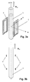
- Such an RF coil arrangement is shown in principle in Figures 3a, b, in Fig. 3a in perspective and in Fig. 3b as a section in the xz-plane.
- An object of the present invention is therefore, in the RF coils according to [1] no annoying magnetization at all Be with these Coils applying the methods according to [2], [3], although their magnetization be substantially eliminated.
- the big problem comes in the subsequent operation, because of an unwanted, mechanical tilting the coils opposite the magnet, these coils can be magnetized again become.
- the present invention should also enable a once-demagnetized coil during the entire further operation always remains demagnetized.
- the good effects of the device according to the invention are also compatible with these coil types ([5], [6]) and even cumulatively, i. by the present invention can also be the remaining, already very small Disturbances of these coil types again by another essential Factor be reduced.
- magnetization then generates an additional magnetic field outside the superconductor, which can cause strong unwanted field disturbances in the sample volume.
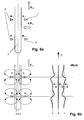
- Fig. 6b the impact of the transverse magnetization is shown schematically on the field disturbances outside of the RF coil, and particularly to the B z components inside the NMR sample.
- transverse magnetic field change we understand an additional magnetic field component_dB T in the coordinate system of the superconducting coil which is perpendicular to the direction of the static magnetic field B 0 existing up to this change. This also corresponds, in the coordinate system of the SL coil, to first order rotation of the static magnetic field with respect to the SL coil, which is also equivalent to rotation of the coil with respect to the static magnetic field.
- the residual ripple of all coils of type [6] is also proportional to transverse magnetization. This in turn can be done with the transversal Magnetic field to be controlled. If the field stays small, so will This transverse magnetization can be small and thus the remaining Residual disturbances are again greatly reduced.
- the present invention adopts the exact diametrically opposite viewpoint and avoids all the above problems by presenting a device which prevents the changes of the transverse field components from the outset .
- the object of the present invention is thus, in an NMR spectrometer the generic type described above, the RF coils with contains superconducting components, no disturbing transversal Magnetization.
- this object is achieved in an equally astonishingly simple and surprisingly effective manner in that a stabilization device is provided which keeps the magnetic field components B T acting transversely to the homogeneous magnetic field B 0 on the superconducting components of the RF resonator.
- the surprising mode of action of the invention is based essentially on the following points:
- the tilts are so extremely small that it is not obvious at first how they should be controlled at all.
- the order of magnitude is how mentioned above, in the range of about 10-100 microns / m or about 100nm-1 ⁇ m / cm. Depending on the exact requirement, therefore, the angular orientation of the superconducting Coils are in this area.
- the above values are based on a magnet with a field of 10T. Tighten at higher fields They meet angle requirements accordingly even further.
- the stabilization device comprises a normally conducting, advantageously cooled and optionally additional superconducting components containing transverse field shield which surrounds the RF resonator circumferentially, with this in a relative tilting controlled manner, in particular rigidly connected tipping is and the force acting on the RF resonator transverse magnetic field components B T at least attenuates.
- the high-frequency noise can be filtered out in a very simple manner become. This can be very beneficial even without further action can be applied, because it can cause vibration-related disturbances lead to field modulation and spectral interference, be filtered out. This may be the only sensible way of doing this high-frequency Fighting disorders, because the compensation methods listed below can not react arbitrarily fast.
- This embodiment is also ideally suited to the active compensation method in the range of high frequencies (e.g., in the range above 10-100 Hz) too complement and thus overall a broadband stabilization throughout Range 0Hz to infinity to achieve. Furthermore, causes such a sign no disadvantages, not even with respect to shimming, because the response it only slows down a bit, but all shim functions are preserved.
- the stabilization device comprises a flat or consisting of discrete wire-shaped or layered conductors, superconducting transversal field shield surrounding the RF resonator circumferentially, with this in a relative tilting controlled manner, in particular is connected rigidly rigid and keeps the transverse magnetic field components B T acting on the RF resonator constant.
- This type of shield can carry persistent currents. In principle, it is therefore suitable to maintain the shielding at arbitrarily low frequencies up to zero. In the case of an implementation of such a shield, ideally then even any further measures are unnecessary, in particular also the active ones. However, there may be problems with shimming and B 0 control (Lock).
- the arrangement has a certain complexity due to the cooling and must be independent of SL coil so that it can be controlled as desired. It is questionable whether the shim values remain sufficiently accurate after cooling below the critical temperature. In addition, in this embodiment usually no Nachshimmen possible, but possibly not even necessary.
- transverse field shield is interrupted in the z direction at one or more points by slots which allow the z component of the homogeneous static magnetic field B 0 to pass unimpeded.
- a field lock works here, but shimming is still not possible without further measures (eg heating via Tc when shimmering, or shim system inside).
- a further particularly preferred embodiment of the NMR spectrometer according to the invention is characterized in that a detection device is provided which measures the transverse magnetic field components B T , that the stabilization device comprises an active compensation device to which the measured transverse magnetic field components B T are fed via feedback or control , and that the active compensation device keeps the transverse magnetic field components in the region of the superconducting components of the RF resonator constant.
- the stabilization device comprises a device for carrying out a rotational movement of the superconducting components of the RF resonator about an axis which is not parallel to the homogeneous magnetic field B 0 .
- any transverse field can be created in their coordinate system in a very effective way.
- B T components are easily possible and there is no dissipation caused by the necessary (for coils) operating current at coils.
- the transverse field is also extremely homogeneous, which is not easy to do with field coils.
- tilting is the exact physical answer to interference caused by tilting. For thin-film coils, all of which are arranged in a plane or parallel to a plane, a single axis which is not perpendicular to this plane and not parallel to B 0 is sufficient.
- the stabilization device may include means for performing rotational movement of the superconducting components of the RF resonator about two axes that are not parallel to one another and that are not parallel to the homogeneous magnetic field B 0 .
- both components must be controlled by B T. This is done with this embodiment of the invention without further difficulties.
- the arrangement requires a higher complexity.
- the stabilization device one or more Magnetic coils includes the transverse magnetic fields in the field of generate superconducting components of the RF resonator.
- This can be a fast actuator without moving parts are used, however the field homogeneity in the design of the coils are considered in advance got to.
- the detection device for measuring the transverse magnetic field components B T comprises one or more Hall probes.
- This solution is very simple and inexpensive, but problems with long-term stability, drifting and disturbing temperature coefficients can occur.
- the arrangement needs a power supply that can potentially cause field disturbances.
- At least one of the Hall probes is coupled to a superconducting loop so as to increase the sensitivity of the Hall probe to the transverse magnetic field component to be measured.
- This also leads to an increased stability of the arrangement, which, however, comes at a higher complexity.
- the transformer loop must not disturb the B 0 field in the region of the NMR sample.
- a heater may also be required to set the zero point. If, for some reason, the loop should "quench", the zero reference is lost.
- the detection device for measuring the transverse magnetic field components B T comprises one or more SQUID sensors, which are coupled to the transverse magnetic field by one or more superconducting loops.
- the detection device for measuring the transverse magnetic field components B T comprises one or more SQUID sensors, which are coupled to the transverse magnetic field by one or more superconducting loops.
- Such an arrangement is extremely sensitive, since a SQUID can detect magnetic fields ⁇ 1G.
- the detection device for measuring the transverse magnetic field components B T comprises one or more electrically conductive pick-up loops, which are periodically tilted and their induced voltages are evaluated.
- This arrangement has a sufficiently high sensitivity, does not use "exotic" technology and when operating correctly always an absolute zero position is given (coil plane exactly perpendicular to B 0 ). The large signal behavior is completely problem-free. The zero reference can not be lost in principle. There are no disturbances of the B 0 field when the amplifier is high-impedance (FET), since then a voltage is induced but no current flows. In addition, no temperature dependence of the arrangement is to be feared. For this application, therefore, such a detector seems ideal.
- the detection device has a device for the phase sensitive detection of the induced voltage in the Pickup loop (s) open. This allows a convenient signal evaluation and has the advantage of static zero drifts in the amplifier electronics do not matter because the payload is different from zero Frequency was modulated.
- the phase-sensitive evaluation of the induced voltage in the pick-up loop should be at the fundamental frequency the tilting movement take place.
- An increase of the useful signal at f with simultaneous reduction of the interference signal at 2f results when two or more oppositely periodically tilted pick-up coils are connected so that the B T signal components add up.
- a pick-up coil or a coil pair or a coil system consisting of a plurality of pick-up coils is provided for each of the degrees of freedom associated with the transverse magnetic field components B T.
- a single pick-up coil, a pair of coils or a coil system can be provided for both with the transverse magnetic field components B T associated degrees of freedom, which is or is periodically tilted about two non-parallel axes. This saves a coil.
- the detection device for measuring the transverse magnetic field components B T comprises an NMR transmitting / receiving system, which determines the absolute value of the magnetic field in the measuring volume by means of the determination of a nuclear magnetic resonance frequency, and in which by means of superconducting, adjacent structures transversal field component changes dB T are converted into longitudinal field component changes dB 0 .
- the SL structure may possibly be arranged on the same substrate as the SL coil itself. This allows a very accurate measurement.
- transverse field component changes dB T acting on the detection device largely correspond to those which act on the superconducting components of the RF resonator, and that a control device, preferably a PID or PID controller, is provided with the detection device measured transverse magnetic field components B T constant, in particular controls to zero.
- the detection device is arranged outside the complete influence of the compensation device, and in which the effect of the compensation device is controlled according to the measured transverse field components such that in the region of the superconducting components of the RF resonator, the transverse magnetic field components B T constant being held.
- the detector can be mounted farther away from the SL coil.
- the correct transverse field components B T can be measured by placing the detection device in close proximity to the superconducting components of the RF resonator.
- the NMR spectrometer in which the detection device in the immediate vicinity of the magnetic center of the magnet arrangement for generating a homogeneous static magnetic field B 0 , in particular within an area with
- the detection device arranged radially outside a gradient system. This results a lesser influence by gradient fields, although the detection device nevertheless very close to the location of the SL coils is arranged. For that must however, radial space is created around the gradient coils.
- a shielded gradient system is used, so that the Influence by gradient fields is negligible.
- the detection device is arranged on the magnetic axis or composed of a plurality of sub-detectors about the z-axis such that it effectively measures the transversal magnetic field components B T occurring on the z-axis. Since the detector can not be exactly at the location of the SL coil, the best possible estimate of B T at the location of the SL coil is determined by averaging the individual measurements.
- Tilts of the SL coil result in minimal lateral displacements, but to mechanical collisions as well as limitations of the possible Tilt angle could lead.
- the axes of rotation of the compensation device run through the superconducting Components of the RF resonator.
- the axes of rotation of the compensation device pass through the detection device. This shifts the detector does not become active during the control processes, and none will introduced additional measurement error, which otherwise affects the quality of the scheme could affect.
- NMR spectrometer in which the compensation device via further Signal inputs has, with which additional corrections of the transversal Fields can be carried out by further influences, in particular by mechanical creep or thermal deformation of components, caused. This results in intervention options for Compensations of known artifacts or malfunctions as well as to Fine tune.
- the compensation device one or more piezo actuators for tilting the superconducting components of the RF resonator exhibit.
- the piezo actuators work in the magnetic field, generating but in turn no magnetic field disturbances.
- the working stroke should be sufficient. There is no power consumption in the resting position.
- the compensation device for tilting the superconducting components of the RF resonator one or more conductor loops, which come with a control electronics supplied currents and by Lorentz forces in the magnetic field to be moved.
- the hub can be almost any size, the solution is inexpensive and are not high voltages, such. for piezo actuators required.
- the scope of the present invention also includes a method for Operation of an NMR spectrometer according to the invention, in which the evaluation the disturbances taking into account known influences, the generated by a shim system takes place. This leaves the control perfecting the transversal field components.
- the evaluation of the Disturbances taking into account known influences caused by a Gradient system are generated. This allows rule disturbances prevent the gradient system, if not by constructive measures can be kept small enough.
- the additional fields which are generated by the switching of gradients in the correction with taken into account and / or that during the time in which the gradient switched is made, no corrections.
- Blanking is the easiest way to disable the above-described disorders. It requires only a digital connection, but no calibration.
- the compensation device is activated before or during the cooling of the superconducting components of the RF resonator, and remains activated during cooling below the transition temperature T c . This not only prevents the subsequent formation of shielding currents in the SL resonator, but from the outset already their emergence.
- the voice coil arrangement is virtually predestined for this mode of operation, since it functions completely independent of temperature, since it requires detectors and actuators which are already active above the transition temperature T c of the SL coil and have the necessary accuracy over the entire temperature range.
- the compensation device is switched on at any desired time, in particular after demagnetization of the superconducting components of the HF resonator, in order to keep the B T fields applied at this time constant. Once a trouble-free state (however) is reached, it can be "frozen".
- NMR spectrometer particularly preferred is a method for operating a According to the invention NMR spectrometer, wherein in addition to a active control at the same time also an attenuation of the high-frequency transverse field components done with a transversal field sign.
- a method for operating a According to the invention NMR spectrometer wherein in addition to a active control at the same time also an attenuation of the high-frequency transverse field components done with a transversal field sign.
- the regulation must never allow deviations from B T above a certain maximum value, otherwise the SL resonator will be magnetized irreversibly by exceeding its critical current, and then either has to be demagnetized or warmed up. This crossing can already happen through arbitrarily short, unregulated excursions, eg by a shock. If the regulation can not be readjusted in full and speed in real time, this inevitably happens. Therefore, a normal-conducting shield as a complement is very valuable, it prevents unchecked rapid B T field changes. Even large B T changes thus come through, but with a limited rate of change, so that the regulation / control can follow this.
- the present invention relates to the field of nuclear magnetic resonance (NMR). In particular, it is about the magnetization and the magnetic Conditioning of superconducting RF coils for receiving RF signals from a sample.
- NMR nuclear magnetic resonance
- RF radio frequency
- the magnet assembly 1 may comprise one or more superconductive coils, which in a vessel 4 with liquid helium within a Cryostats 5 is housed with a room temperature hole 6. To the To keep heat conduction as low as possible, the vessel 4 in an insulating vacuum 7 within the cryostat 5 by means of a vertical suspension 8 and a lateral suspension 9 arranged. Furthermore, the Arrangement a shim system 10 and a probe head 11, in which the RF resonator 2 is housed. By an insulating vacuum 12 are cooling lines 13 for cooling the SL elements of the RF resonator 2 via a Heat exchanger 15 out. Finally, the arrangement also has a Supply line 14 for tempering air to the sample tube 3 in the probe head 11th on.
- the object of the present invention is, in all known superconducting RF coils, the disturbances caused by the coil of the static Magnetic field and thereby virtually eliminate artifacts in the spectra or to significantly reduce over the prior art, as well as during to keep the entire duration of use low.
- the Device according to the invention ensure trouble-free long-term operation. This is achieved by active control of the transverse field components and / or by their passive shielding by means of normal or superconducting shields.
- the compensation device is technically quite well feasible, be it through active mechanical tilting of the superconducting RF coils or by additional transverse field coils. But there are also implementation variants possible in which the entire magnetic coil of the NMR magnet in their orientation is controlled.
- the difficulty of an active arrangement is certainly one suitable detector that sensitive to the extremely small transverse fields and must measure stable.
- the practical feasibility of active realization The present invention is narrow enough with the feasibility of one linked to a good detector.
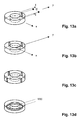
- Such a transverse field detector is in various Embodiments in the figures 13 a to d shown in principle.
- a Hall probe which is a component (e.g., By) of the transverse magnetic field ( Figure 13a), where Toroid is arranged about the symmetry axis of the probe head 11 (see e.g. Transverse field detector 20 in Fig. 1).
- the inner implementation can but quite different, such as with two or four Hall probes (Fig. 13b, 13c), or else an oscillating pick-up coil (FIG. 13d, explanations see below).
- the detector does not necessarily have to be installed in the probe itself but can be placed in principle at any position of the NMR system in which the relationship between the orientation of the NMR Coils and the detector is defined.
- the detector can also be implemented as part of the shim or even the magnet system itself.
- FIG. 15a A coil with an area of about 1 cm 2 , which is wound with 100 - 1000 turns of a thin wire, is aligned with the surface first exactly perpendicular to the B 0 field.
- This coil has one or more mechanical actuators 22 which allow them to be periodically oscillated around the starting position by one (or two) axes which lie in the coil plane and are perpendicular to B 0 .
- the frequency of the oscillation can typically be in the range 1 kHz-10 kHz.
- the amplitude can be very small, typically about 100-1000 nm.
- the coil is connected to a sensitive voltage amplifier, with a spectral noise density of typically 1nV / Hz 0.5 .
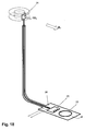
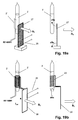
- FIG. 16 a shows the periodic tilting alpha (t) of the coil about the y-axis with respect to its rest position in a plane xy perpendicular to B 0 .
- This useful signal is superimposed by the background signal, derived from B 0 .
- this can be easily separated using a lock-in amplifier because the background signal occurs at twice the frequency as the wanted signal. Since the background signal is quadratic and the wanted signal depends linearly on the oscillation amplitude, the interference by the background signal in relation to the useful signal can be made arbitrarily small by the suitable choice of a sufficiently small oscillation amplitude.
- An arrangement of two coils is used, which are parallel to each other are arranged to have parallel axes to swing these in sync, but with opposite phase (FIG. 15b).
- the outputs of the two coils are connected in series and fed to the amplifier.
- the polarity of Series switching is chosen so that the transversal signals add up.
- the tilts become one with this Purpose dedicated special actuator 22 generates. This does not have to be mandatory so, arrangements are possible in which the compensation device (s.u.) By a periodic additional signal at the same time also for signal generation can be used.
- a detector for transverse fields such as a stable Hall probe, which is positioned with its sensitive direction perpendicular to the B 0 field (FIG. 13 b). It then measures the transverse field component of the magnetic field. This can be further increased in sensitivity with a small superconducting transformer as needed ( Figures 14a and 14b).
- FIG. 18 illustrated SQUID detector with a SQUID 23 and a pick-up loop 24.
- SQUID Superconducting Quantum Interference Device
- the SQUID is not even in the magnetic field works, here must be a superconducting loop 25 as Flow transformer can be used as in the application of SQUID's for magnetic field and magnetization measurements is common.
- the Shielded signal line at the tap of the superconducting loop 25 is with a heating device 26 heated.
- the pick-up loop 25 must be oriented perpendicular to the B 0 field in the direction of the transverse magnetic field components B T to be measured.
- This sample 3 is then measured for its NMR resonance frequency in a continuous or periodic measurement (analogous to the NMR field lock) with the aid of an RF coil 2' leading to an NMR auxiliary spektrometer device.
- the deviation from the desired frequency then directly gives a measure of the transverse field component B T , which acts in the direction perpendicular to the superconducting surface 27 or loop 28.
- a transversal field detector in one of the above or other conceivable embodiments, can now be used to measure one (eg B x ) or both (eg B y ) components of the transverse magnetic field.
- B x eg B x
- B y superconductor plane
- FIG. 1 A schematic diagram of a preferred implementation of the device according to the invention is shown in FIG.
- the transverse field detector 20 thus measures the occurring transverse magnetic field components B T.
- the output of the detector 20 is then linked by means of a control device to an actuator 22 of a compensation device (tilting of the coils about a fulcrum 19).
- This compensation device now ensures by means of a control / regulating circuit 29 that the transverse field components B T are always returned to the original state at the location of the superconducting RF coils 2 when a deviation occurs.
- the SL coils are e.g. at a tilt of the magnet in the same Direction and at exactly the same angle parallel to the magnet with tilted.
- the drive of the tilting mechanism can preferably be accomplished by piezoelectric actuators or else by electromagnetic forces acting on field coils, which are preferably in the magnetic field B 0 of the NMR magnet. But other drives, such as by piezoelectric motors, electric motors, stepper motors or the like. Can be realized.
- the compensation device can also consist of field coils 30, which generate an additional transverse field in a desired strength and direction. This is then controlled so that the transverse magnetic field components B T remain unchanged at the coil location (FIG. 11, as well as FIG. 12 for both components B x and B y ).
- These field coils 30 can be mounted in the probe head 11, in the shim system or else on or in the cryo magnet.
- the transverse field detector shown in Fig. 1 becomes 20 as close as possible to the superconducting coils, immovable, i. rigidly connected to the probe head 11 (see detector 20 "in Fig. 9), so that he as accurately as possible actually measures transversal field components acting on the coils.
- the control device the compensation device consisting of a device for tilting the RF coils, so that control the superconducting RF coils always remain in the constant transverse field.
- the transverse field detector 20 placed as close as possible to the superconducting RF coils 2, and rigidly angularly connected to them (see Fig. 10).
- the compensation device now tilts the RF coils 2 together with the detector 20th around the axis of rotation 19 '.
- the control device may simply be the compensation device Always control so that the detector 20 always in constant transverse field remains, and thus also the RF coils. 2
- the detector It is always convenient to place the detector in the homogeneous field area, because then it is ensured that the detector has the same fields measures how the RF coils 2 experience.
- a good measure is the detector in the Area where the field gradients are less than 100G / mm.
- the detector may also be placed at a certain distance from the RF coils 2 ( Figure 11, position B), if required by technical or design requirements.
- the interferences that the detector measures are no longer necessarily identical to those acting on the superconducting RF coils.
- the compensation device no longer has to act equally on the RF coils and the detector.
- more complex algorithms are needed to ensure the constancy of the B T fields (via simple control of the compensation angle, or beyond a zero control on the detector). Arrangements of several sensors at different locations are also possible, from which then the effective B T field is determined at the location of the coils and from this the necessary compensation is determined.
- control algorithms can be used in the widest range Range adapted to the problem
- the scheme can be analog or digital and the control bandwidth can be chosen to be e.g. just slow disturbances are compensated, or else vibrations and Vibrations with a fast control loop to be compensated.
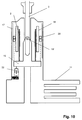
- a very convenient configuration is the connection of the compensation device with a normal conducting magnetic field shield 17 (see Fig. 20).
- the high-frequency noise (vibrations, etc.) are filtered out, and the low-frequency and quasi-static can now work well with the compensation device be corrected.
- the shield 17 is rigidly connected to the probe head 11, and the assembly consisting of the superconducting resonator 2 and the detector 21 is tiltably controlled about the axis 19 opposite the probe head 11, so that the remaining, through the shield 17 attenuated and thus slow B T changes can be precisely controlled with a relatively fast control loop in a simple manner.
- This principle of coupling passive and active stabilization can also be applied to a superconductive shield.
- the devices that apply the corrections with tilting are also different variants conceivable, in particular, the axes of rotation 19 '(one or both directions) advantageously at the magnetic center be placed (see Fig. 10). This has the advantage that the RF coils 2 are moved as little as possible laterally.
- the detector 20 is not placed directly at the RF coils 2, so can Also advantageous is an arrangement in which the axis of rotation 19 through the Detector 20 goes (see Fig. 1). Thus, with co-moved detector 20th no lateral positioning errors due to the correction movements themselves, which can lead to additional measurement errors transmitted to the detector 20.
- the systems can be constructed so that the actuator 22 does not act on the detector 20. Then, the actuator 22 is detected by the detector signal controlled so that the transverse field acting on the RF coils 2 acts, is kept constant.
- this requires a very accurate Calibration of the system to achieve adequate accuracy (equivalent Example in Fig. 8 or Fig. 9).
- a shim system 10 is shown schematically. It generates at Shimmer more, additional field changes. These are, however, i.A. very small (magnitude of the full shim strengths are typically a few G / cm) and can be neglected, especially if only small Shim changes are made. They typically work neither on the RF coils 2 nor on the detector 20 significantly. This one Disturbances, however, are known, they can if necessary with in the control algorithm be fed, so that this from the Shimsystem 10 additional components automatically calculated and if so desired, corrected.
- a gradient system 18 (shown in FIGS. 9, 10, 20) generates additional magnetic fields in the sample volume which generate linear variable B z components, with a dependence of B z on x, y, or z direction. These gradients are called "X, Y, or Z gradients". They produce significant changes in the transverse field of the order of 10 G / cm and more and can lead to unwanted regulatory actions of the system.
Landscapes
- Physics & Mathematics (AREA)
- Condensed Matter Physics & Semiconductors (AREA)
- General Physics & Mathematics (AREA)
- Magnetic Resonance Imaging Apparatus (AREA)
Abstract
Description
- Fig. 1
- eine Prinzipskizze der erfindungsgemäßen Vorrichtung im schematischen Vertikalschnitt;
- Fig. 2
- einen schematischen Vertikalschnitt durch ein NMR-Spektrometer mit supraleitfähigen Magnetspulen und Kryostat nach dem Stand der Technik;
- Fig. 3
- ein Beispiel für eine supraleitende HF-Empfangsspulenanordnung nach dem Stand der Technik , und zwar in Fig. 3a perspektivisch und in Fig. 3b als Schnitt in der xz-Ebene;
- Fig. 4
- die Magnetfeldlinien der Grundfeldspule im ungestörten Fall;
- Fig. 5
- die Magnetfeldlinien der Grundfeldspule im gestörten Fall und zwar in Fig. 5a durch Verkippung der HF-Empfangsspulenanordnung und in Fig. 5b durch Verkippung des Magnetspulensystems;
- Fig. 6
-
- a) die transversale Magnetisierung MT
- b) die Auswirkungen einer Änderung der transversalen Magnetfeldkomponenten dBT auf die Homogenität der Magnetfeldkomponente Bz am Probenort;
- Fig. 7
- eine schematische räumliche Ansicht einer erfindungsgemäßen Anordnung zur Kontrolle von Bx und By mit 2 Freiheitsgraden (Verkippung);
- Fig. 8
- einen schematischen Vertikalschnitt durch eine Anordnung mit Verkippung der Spulen, aber mit fixem Detektor;
- Fig. 9
- eine Anordnung mit Detektor außen an einem Gradientensystem;
- Fig.10
- eine Anordnung mit Drehachse innerhalb des Bereichs der HF-Empfangsspulenanordnung;
- Fig.11
- eine Anordnung mit Kompensation durch Einsatz von Feldspulen;
- Fig.12
- eine räumliche Skizze einer Anordnung mit 2 Feldspulen zur Kontrolle der Magnetfeldkomponenten Bx und By;
- Fig.13a-d
- prinzipielle Anordnung einer erfindungsgemäßen Detektionsvorrichtung in mehreren Ausführungsformen;
- Fig.14a,b
- die Verstärkung der Empfindlichkeit einer Hall-Sonde durch einen SL Transformator;
- Fig.15a
- die grundsätzliche Anordnung eines Detektors mit Induktionsschleife;
- Fig.15b
- die Detektoranordnung mit kompensiertem Einfluss des homogenen Magnetfelds B0;
- Fig.16a-f
- eine Analyse der Funktionsweise einer Detektoranordnung mit Induktionsschlaufe;
- Fig.17
- Ausführungen einer Detektoranordnung mit Induktionsschlaufe und 2 Detektionsrichtungen, und zwar in a) asymmetrischer und b) symmetrischer Anordnung;
- Fig.18
- einen Transversalfeld-Detektor mit SQUID;
- Fig.19
- einen Transversalfeld-Detektor unter Ausnutzung von NMR-Signalen und mit SL Element;
- Fig.20
- ein Transversalfeld-Schild in schematischem Vertikalschnitt; und
- Fig.21a-f
- Ausführungsformen des Transversalfeld-Schildes nach Fig. 20.
Claims (15)
- Kernspinresonanz (=NMR)-Spektrometer mit einer Magnetanordnung (1) zur Erzeugung eines homogenen statischen Magnetfeldes B0 in Richtung einer z-Achse, sowie mit einem Hochfrequenz (=HF)-Resonator (2) zum Empfang von NMR-Signalen aus einem Messvolumen, der eine oder mehrere supraleitende Komponenten enthält,
dadurch gekennzeichnet, dass eine Stabilisierungsvorrichtung vorgesehen ist, die auf die supraleitenden Komponenten des HF-Resonators (2) wirkende Magnetfeldkomponenten BT transversal zum homogenen Magnetfeld B0 konstant hält. - NMR-Spektrometer nach Anspruch 1, dadurch gekennzeichnet, dass die Stabilisierungsvorrichtung einen normalleitende und gegebenenfalls zusätzliche supraleitende Komponenten enthaltenden Transversalfeld-Schild (17) umfasst, der den HF-Resonator (2) umfänglich umgibt, mit diesem in einer bezüglich der relativen Verkippung kontrollierten Weise, insbesondere verkippungssicher starr verbunden ist und die auf den HF-Resonator (2) wirkenden transversalen Magnetfeldkomponenten BT zumindest dämpft.
- NMR-Spektrometer nach einem der vorhergehenden Ansprüche dadurch gekennzeichnet, dass die Stabilisierungsvorrichtung eine Einrichtung (22) zur Durchführung einer Drehbewegung der supraleitenden Komponenten des HF-Resonators (2) um eine oder zwei nicht untereinander parallele und nicht zum homogenen Magnetfeld B0 parallele Achsen umfasst.
- NMR-Spektrometer nach einem der vorhergehenden Ansprüche, dadurch gekennzeichnet, dass eine Detektionsvorrichtung (20) vorgesehen ist, die die transversalen Magnetfeldkomponenten BT misst, dass die Stabilisierungsvorrichtung eine aktive Kompensationsvorrichtung umfasst, der über eine Rückkopplung oder Steuerung (29) die gemessenen transversalen Magnetfeldkomponenten BT zugeführt werden, und dass die aktive Kompensationsvorrichtung die transversalen Magnetfeldkomponenten im Bereich der supraleitenden Komponenten des HF-Resonators (2) konstant hält.
- NMR-Spektrometer nach Anspruch 4 dadurch gekennzeichnet, dass die Detektions-vorrichtung (20) zur Messung der transversalen Magnetfeld-komponenten BT eine oder mehrere Hall-Sonden umfasst, und dass mindestens eine der Hall-Sonden mit einer supraleitenden Schlaufe so gekoppelt ist, dass diese die Empfindlichkeit der Hall-Sonde auf die zu messende transversale Magnetfeldkomponente steigert.
- NMR-Spektrometer nach Anspruch 4 oder 5 dadurch gekennzeichnet, dass die Detektionsvorrichtung (20) zur Messung der transversalen Magnetfeldkomponenten BT eine oder mehrere elektrisch leitende Pick-Up Schlaufen (24) umfasst, die periodisch verkippt und deren induzierte Spannungen ausgewertet werden.
- NMR-Spektrometer nach Anspruch 6, dadurch gekennzeichnet, dass die Detektionsvorrichtung (20) eine Einrichtung zur phasensensitive Detektion der induzierten Spannung in der (den) Pick-Up Schlaufe(n) (24) aufweist, und dass die phasensensitive Auswertung der induzierten Spannung in der Pick-Up Schlaufe (24) mit der Grundfrequenz der Kippbewegung erfolgt.
- NMR-Spektrometer nach einem der Ansprüche 6 oder 7, dadurch gekennzeichnet, dass zwei oder mehrere entgegengesetzt periodisch verkippte Pick-Up Spulen (24) so geschaltet sind, dass sich die BT - Signalkomponenten addieren, und dass die entgegengesetzt verkippten Spulen so dimensioniert sind, mit solchen Kippamplituden betrieben werden und so geschaltet sind, dass sich die sich durch das homogene Magnetfeld B0 ergebenden Signalkomponenten möglichst exakt subtrahieren.
- NMR-Spektrometer nach einem der Ansprüche 4 bis 8, dadurch gekennzeichnet, dass die Detektions-vorrichtung (20) zur Messung der transversalen Magnetfeld-komponenten BT ein NMR Sende/Empfangssystem umfasst, das mittels der Bestimmung einer Kernresonanzfrequenz den absoluten Betrag des Magnetfelds in der Messvolumens bestimmt, und bei dem mittels supraleitender, benachbarter Strukturen transversale Feldkomponentenänderungen dBT in longitudinale Feldkomponentenänderungen dB0 umgewandelt werden.
- NMR-Spektrometer nach einem der Ansprüche 4 bis 9, dadurch gekennzeichnet, dass die Detektions-vorrichtung (20') auf der Magnetachse angeordnet oder so aus mehreren Teildetektoren um die z-Achse herum zusammengesetzt ist, dass sie effektiv die auf der z-Achse auftretenden transversalen Magnetfeldkomponenten BT misst.
- NMR-Spektrometer nach einem der Ansprüche 4 bis 10, dadurch gekennzeichnet, dass die Kompensationsvorrichtung einen oder mehrere Piezo-Aktuatoren (22) zur Verkippung der supraleitenden Komponenten des HF-Resonators (2) aufweist.
- Verfahren zum Betrieb eines NMR-Spektrometers nach einem der vorhergehenden Ansprüche, dadurch gekennzeichnet, dass die Auswertung der Störungen unter Berücksichtigung von bekannten Einflüssen, die durch ein Shimsystem (10) erzeugt werden, erfolgt, und dass die Zusatzfelder, die durch Veränderungen der Einstellung des Shimsystems (10) erzeugt werden, bei der Korrektur mit einberechnet werden.
- Verfahren zum Betrieb eines NMR-Spektrometers nach einem der vorhergehenden Ansprüche, dadurch gekennzeichnet, dass die Auswertung der Störungen unter Berücksichtigung von bekannten Einflüssen, die durch ein Gradientensystem (18) erzeugt werden, erfolgt, und dass die Zusatzfelder, die durch das Schalten von Gradienten erzeugt werden, bei der Korrektur mit berücksichtigt werden und/oder dass während der Zeit, in der der Gradient geschaltet wird, keine Korrekturen vorgenommen werden.
- Verfahren zum Betrieb eines NMR-Spektrometers nach einem der Ansprüche 4 bis 13, dadurch gekennzeichnet, dass die Kompensationsvorrichtung bereits vor oder während des Abkühlens der supraleitenden Komponenten des HF-Resonators (2) aktiviert wird, und dass sie während der Kühlung unter die Sprungtemperatur Tc aktiviert bleibt.
- Verfahren zum Betrieb eines NMR-Spektrometers nach einem der vorhergehenden Ansprüche, dadurch gekennzeichnet, dass zusätzlich zu einer aktiven Kontrolle gleichzeitig auch eine Dämpfung der hochfrequenten Transversalfeldkomponenten mit einem Transversalfeld-Schild (17) nach Anspruch 2 erfolgt.
Applications Claiming Priority (2)
| Application Number | Priority Date | Filing Date | Title |
|---|---|---|---|
| DE10157972 | 2001-11-27 | ||
| DE10157972A DE10157972B4 (de) | 2001-11-27 | 2001-11-27 | NMR-Spektrometer und Betriebsverfahren mit Stabilisierung der transversalen Magnetisierung bei supraleitenden NMR-Resonatoren |
Publications (3)
| Publication Number | Publication Date |
|---|---|
| EP1314994A2 true EP1314994A2 (de) | 2003-05-28 |
| EP1314994A3 EP1314994A3 (de) | 2004-10-27 |
| EP1314994B1 EP1314994B1 (de) | 2008-03-05 |
Family
ID=7707018
Family Applications (1)
| Application Number | Title | Priority Date | Filing Date |
|---|---|---|---|
| EP02025787A Expired - Lifetime EP1314994B1 (de) | 2001-11-27 | 2002-11-16 | Stabilisierung der transversalen Magnetisierung bei supraleitenden NMR-Resonatoren |
Country Status (4)
| Country | Link |
|---|---|
| US (1) | US6833701B2 (de) |
| EP (1) | EP1314994B1 (de) |
| JP (1) | JP3787550B2 (de) |
| DE (1) | DE10157972B4 (de) |
Cited By (1)
| Publication number | Priority date | Publication date | Assignee | Title |
|---|---|---|---|---|
| EP1331489A3 (de) * | 2002-01-29 | 2005-04-20 | Bruker BioSpin AG | Magnetische Homogenisierung von Supraleitenden HF-Spulen für den Empfang von NMR-Signalen |
Families Citing this family (17)
| Publication number | Priority date | Publication date | Assignee | Title |
|---|---|---|---|---|
| US6335622B1 (en) * | 1992-08-25 | 2002-01-01 | Superconductor Technologies, Inc. | Superconducting control elements for RF antennas |
| DE10033869C2 (de) * | 2000-07-12 | 2003-07-31 | Karlsruhe Forschzent | HTS-Kryomagnet und Aufmagnetisierungsverfahren |
| GB0225898D0 (en) * | 2002-11-06 | 2002-12-11 | Oxford Instr Superconductivity | Apparatus for use in nmr system |
| DE10340352B4 (de) * | 2003-09-02 | 2005-10-20 | Bruker Biospin Ag Faellanden | Kryokopf mit mehreren Wärmetauschern für die Kühlung der HF-Spulen oder Resonatoren |
| US7782059B2 (en) * | 2004-11-23 | 2010-08-24 | M2M Imaging Corp. | Bandwidth expansion in magnetic resonance |
| DE102005013620B3 (de) * | 2005-03-24 | 2006-07-27 | Bruker Biospin Ag | Kryostatanordnung mit thermisch kompensierter Zentrierung |
| US7573268B2 (en) * | 2006-02-22 | 2009-08-11 | Los Alamos National Security, Llc | Direct imaging of neural currents using ultra-low field magnetic resonance techniques |
| JP4851261B2 (ja) * | 2006-08-17 | 2012-01-11 | 株式会社神戸製鋼所 | 冷却式nmrプローブヘッド |
| DE102006046888B4 (de) * | 2006-10-04 | 2010-12-16 | Bruker Biospin Ag | Gekühlter Magnet-Resonanz-Probenkopf mit einem Vakuumbehälter sowie zugehörige NMR-Messapparatur |
| DE102006052076A1 (de) * | 2006-11-04 | 2008-05-08 | Bruker Biospin Ag | Probenhalter für NMR-Messungen mit Feldhomogenisierung im Probenvolumen durch die Grenzflächen des Probenbehälters |
| GB2456795B (en) * | 2008-01-24 | 2010-03-31 | Siemens Magnet Technology Ltd | A limiter for limiting the motion of components in a cryostat |
| DE102011006164B8 (de) * | 2011-03-25 | 2013-04-18 | Bruker Biospin Ag | Kompakter kryogener NMR-Sensor mit integriertem, aktivem Kühlaggregat |
| DE102011086658B3 (de) * | 2011-11-18 | 2013-03-28 | Siemens Aktiengesellschaft | Von Gradienten unabhängige Shimspule für eine Lokalspule einer Magnetresonanzeinrichtung, Lokalspule, Magnetresonanzeinrichtung, sowie Verfahren zur Platzierung einer Shimspuleneinrichtung |
| JP5904326B2 (ja) * | 2012-01-06 | 2016-04-13 | 日本電子株式会社 | Nmr装置のセットアップ方法 |
| DE102013212312B4 (de) * | 2013-06-26 | 2017-02-02 | Bruker Biospin Ag | NMR-Probenkopf mit verbesserter Zentrierung des Probenröhrchens |
| JP6549857B2 (ja) * | 2015-02-18 | 2019-07-24 | 日本電子株式会社 | 磁気共鳴信号検出モジュール |
| JP7306636B2 (ja) * | 2020-03-31 | 2023-07-11 | 日本電子株式会社 | Nmr測定プローブ |
Family Cites Families (28)
| Publication number | Priority date | Publication date | Assignee | Title |
|---|---|---|---|---|
| CH417155A (de) * | 1964-07-23 | 1966-07-15 | Trueb Taeuber & Co Ag | Kernresonanzspektrograph |
| US3609519A (en) * | 1967-11-22 | 1971-09-28 | Jeol Ltd | Apparatus for maintaining field frequency control in a gyromagnetic instrument |
| FR2000229A1 (de) * | 1968-01-15 | 1969-09-05 | Sp Konstruktor | |
| CH520930A (de) * | 1970-03-12 | 1972-03-31 | Spectrospin Ag | Vorrichtung zur Stabilisierung des Magnetfeldes eines Kernresonanzgerätes |
| US3826972A (en) * | 1973-08-17 | 1974-07-30 | Univ Leland Stanford Junior | Method and apparatus for detecting nuclear magnetic resonance |
| US4110681A (en) * | 1977-02-16 | 1978-08-29 | International Business Machines Corporation | NMR field frequency lock system |
| JPS5485093A (en) * | 1977-12-20 | 1979-07-06 | Hitachi Ltd | Magnetic field stabilizing apparatus in nuclear magnetic resonator |
| US4685468A (en) * | 1983-03-18 | 1987-08-11 | Albert Macovski | NMR imaging system using field compensation |
| FR2574945B1 (fr) * | 1984-12-14 | 1987-01-16 | Thomson Cgr | Procede de regulation du champ magnetique delivre par un aimant resistif, systeme d'aimant resistif mettant en oeuvre ce procede et installation d'imagerie par resonance magnetique nucleaire incorporant un tel systeme |
| NL8801162A (nl) * | 1988-05-04 | 1989-12-01 | Philips Nv | Supergeleidend magneetstelsel met supergeleidende cylinders. |
| GB2227095B (en) * | 1989-01-03 | 1993-01-27 | Instrumentarium Corp | Magnetic resonance imaging apparatus and method |
| DE4013111C2 (de) * | 1990-04-25 | 1994-05-26 | Spectrospin Ag | HF-Empfangsspulenanordnung für NMR-Spektrometer |
| US5214383A (en) * | 1990-10-29 | 1993-05-25 | Resonex, Inc. | MRI apparatus with external magnetic field compensation |
| US5166620A (en) * | 1990-11-07 | 1992-11-24 | Advanced Techtronics, Inc. | Nmr frequency locking circuit |
| US5585723A (en) * | 1995-03-23 | 1996-12-17 | Conductus, Inc. | Inductively coupled superconducting coil assembly |
| US5572127A (en) * | 1994-08-29 | 1996-11-05 | Conductus, Inc. | Inhomogeneities in static magnetic fields near superconducting coils |
| DE69526095T2 (de) * | 1995-12-20 | 2002-11-14 | Bruker Biospin Ag, Faellanden | Probenkopf für ein NMR-Spektrometer |
| US6037775A (en) * | 1996-08-13 | 2000-03-14 | Fonar Corporation | Method and apparatus for magnetic field stabilization in a MRI system |
| DE19733574C2 (de) * | 1997-08-02 | 2000-04-06 | Bruker Ag | Supraleitender Hybrid-Resonator für den Empfang für NMR-Signalen |
| US6097187A (en) * | 1997-08-21 | 2000-08-01 | Picker International, Inc. | MRI magnet with fast ramp up capability for interventional imaging |
| US6025719A (en) * | 1997-11-07 | 2000-02-15 | Varian, Inc. | Nuclear magnetic resonance method and apparatus |
| US6201392B1 (en) * | 1997-11-07 | 2001-03-13 | Varian, Inc. | Coplanar RF probe coil arrangement for multifrequency excitation |
| US5986453A (en) * | 1997-11-07 | 1999-11-16 | Varian, Inc. | AC magnetic susceptibility control of superconducting materials in nuclear magnetic resonance (NMR) probes |
| US6054855A (en) * | 1997-11-07 | 2000-04-25 | Varian, Inc. | Magnetic susceptibility control of superconducting materials in nuclear magnetic resonance (NMR) probes |
| DE10006324C1 (de) * | 2000-02-12 | 2001-08-16 | Bruker Ag Faellanden | Gekühlter NMR-Probenkopf mit Vorrichtung zur Zentrierung der Meßprobe |
| DE10006317C1 (de) * | 2000-02-12 | 2001-08-16 | Bruker Ag Faellanden | Gekühlter NMR-Probenkopf mit thermischer Isolation der Meßprobe |
| DE10006323C1 (de) * | 2000-02-12 | 2001-08-09 | Bruker Ag Faellanden | Gekühlter NMR-Probenkopf mit gleichmäßiger Temperierung der Meßprobe |
| US6411092B1 (en) * | 2000-09-30 | 2002-06-25 | Varian, Inc. | Clad metal foils for low temperature NMR probe RF coils |
-
2001
- 2001-11-27 DE DE10157972A patent/DE10157972B4/de not_active Expired - Lifetime
-
2002
- 2002-11-05 US US10/287,882 patent/US6833701B2/en not_active Expired - Lifetime
- 2002-11-16 EP EP02025787A patent/EP1314994B1/de not_active Expired - Lifetime
- 2002-11-27 JP JP2002343933A patent/JP3787550B2/ja not_active Expired - Lifetime
Cited By (1)
| Publication number | Priority date | Publication date | Assignee | Title |
|---|---|---|---|---|
| EP1331489A3 (de) * | 2002-01-29 | 2005-04-20 | Bruker BioSpin AG | Magnetische Homogenisierung von Supraleitenden HF-Spulen für den Empfang von NMR-Signalen |
Also Published As
| Publication number | Publication date |
|---|---|
| DE10157972A1 (de) | 2003-06-12 |
| EP1314994B1 (de) | 2008-03-05 |
| US6833701B2 (en) | 2004-12-21 |
| US20030098689A1 (en) | 2003-05-29 |
| JP2003194904A (ja) | 2003-07-09 |
| EP1314994A3 (de) | 2004-10-27 |
| DE10157972B4 (de) | 2004-01-08 |
| JP3787550B2 (ja) | 2006-06-21 |
Similar Documents
| Publication | Publication Date | Title |
|---|---|---|
| EP1314994B1 (de) | Stabilisierung der transversalen Magnetisierung bei supraleitenden NMR-Resonatoren | |
| DE4101481C2 (de) | Anordnung zum Kompensieren externer Magnetfeldstörungen bei einem Kernresonanzspektrometer mit supraleitender Magnetspule | |
| EP0257371B1 (de) | Vorrichtung zum Kompensieren von zeitvarianten Feldstörungen in Magnetfeldern | |
| EP0116364B1 (de) | Kühleinrichtung für ein Tieftemperatur-Magnetsystem | |
| EP0111827B2 (de) | Vorrichtung zur mehrkanaligen Messung schwacher, sich ändernder Magnetfelder und Verfahren zu ihrer Herstellung | |
| DE69831225T2 (de) | Verringerung der effektiven magnetischen suszeptibilität von supraleitenden rf-spulen in kernspinresonanz-sonden | |
| DE4030371A1 (de) | Quadraturoberflaechenspulenanordnung | |
| DE19536390A1 (de) | Anordnung zur Messung und Regelung des Grundfeldes eines Magneten eines Kernspintomographiegerätes | |
| DE3529815A1 (de) | Messvorrichtung mit einem squid-magnetometer | |
| DE4237011A1 (de) | ||
| WO2015135513A1 (de) | Supraleitender magnetfeldstabilisator | |
| DE69709453T2 (de) | Supraleitender Jochmagnet für die magnetische Resonanz und Methode zu seiner Erregung | |
| DE102005040539B4 (de) | Magnetfeldsensitive Sensoreinrichtung | |
| DE4419061A1 (de) | Anordnung zur Messung und Regelung des Grundfeldes eines Magneten eines Kernspintomographiegerätes | |
| DE10133655A1 (de) | Magnet-Resonanz-Tomographiegerät mit verbesserter örtlicher und zeitlicher Stabilisierung der Homogenität des magnetischen Grundfeldes | |
| DE102004005744A1 (de) | Driftkompensiertes supraleitendes Magnetsystem | |
| DE3400861A1 (de) | Kernspintomograph | |
| DE10227877B4 (de) | Aktiv abgeschirmte, supraleitende Magnetanordnung mit einer Vorrichtung zur zusätzlichen Streufeldoptimierung | |
| DE19702831A1 (de) | Vorrichtung zur Kompensation von externen Feldstörungen des Grundmagnetfeldes bei Kernspintomographen | |
| DE10200861A1 (de) | Magnetresonanzgerät mit einem Wirbelstromerzeuger | |
| DE69735617T2 (de) | Mr-gerät mit mitteln zur reduzierung des auswirkungen von begleitenden gradienten | |
| DE10203279C1 (de) | Verfahren zur Beeinflussung des homogenen statischen Magnetfelds in einer NMR-Apparatur und zugehöriger NMR-Resonator | |
| EP0500618B1 (de) | Gradientenerzeugungssystem, kernspintomograph und verfahren zur bilderzeugung mit einem kernspintomographen | |
| EP4310529A1 (de) | Aktive reduzierung eines temperaturindizierten shimdrifts bei nmr-magnetsystemen | |
| EP1191345B1 (de) | Magnetanordnung mit einem supraleitenden Magnetspulensystem und einer ferromagnetischen Feldform-Vorrichtung |
Legal Events
| Date | Code | Title | Description |
|---|---|---|---|
| PUAI | Public reference made under article 153(3) epc to a published international application that has entered the european phase |
Free format text: ORIGINAL CODE: 0009012 |
|
| AK | Designated contracting states |
Designated state(s): AT BE BG CH CY CZ DE DK EE ES FI FR GB GR IE IT LI LU MC NL PT SE SK TR |
|
| AX | Request for extension of the european patent |
Extension state: AL LT LV MK RO SI |
|
| PUAL | Search report despatched |
Free format text: ORIGINAL CODE: 0009013 |
|
| AK | Designated contracting states |
Kind code of ref document: A3 Designated state(s): AT BE BG CH CY CZ DE DK EE ES FI FR GB GR IE IT LI LU MC NL PT SE SK TR |
|
| AX | Request for extension of the european patent |
Extension state: AL LT LV MK RO SI |
|
| 17P | Request for examination filed |
Effective date: 20041002 |
|
| AKX | Designation fees paid |
Designated state(s): CH DE FR GB LI |
|
| 17Q | First examination report despatched |
Effective date: 20070109 |
|
| GRAP | Despatch of communication of intention to grant a patent |
Free format text: ORIGINAL CODE: EPIDOSNIGR1 |
|
| GRAS | Grant fee paid |
Free format text: ORIGINAL CODE: EPIDOSNIGR3 |
|
| GRAA | (expected) grant |
Free format text: ORIGINAL CODE: 0009210 |
|
| AK | Designated contracting states |
Kind code of ref document: B1 Designated state(s): CH FR GB LI |
|
| RBV | Designated contracting states (corrected) |
Designated state(s): CH FR GB LI |
|
| REG | Reference to a national code |
Ref country code: GB Ref legal event code: FG4D Free format text: NOT ENGLISH |
|
| REG | Reference to a national code |
Ref country code: CH Ref legal event code: EP |
|
| REG | Reference to a national code |
Ref country code: DE Ref legal event code: 8566 |
|
| ET | Fr: translation filed | ||
| PLBE | No opposition filed within time limit |
Free format text: ORIGINAL CODE: 0009261 |
|
| STAA | Information on the status of an ep patent application or granted ep patent |
Free format text: STATUS: NO OPPOSITION FILED WITHIN TIME LIMIT |
|
| 26N | No opposition filed |
Effective date: 20081208 |
|
| REG | Reference to a national code |
Ref country code: FR Ref legal event code: PLFP Year of fee payment: 14 |
|
| REG | Reference to a national code |
Ref country code: FR Ref legal event code: PLFP Year of fee payment: 15 |
|
| REG | Reference to a national code |
Ref country code: FR Ref legal event code: PLFP Year of fee payment: 16 |
|
| REG | Reference to a national code |
Ref country code: CH Ref legal event code: PFA Owner name: BRUKER SWITZERLAND AG, CH Free format text: FORMER OWNER: BRUKER BIOSPIN AG, CH |
|
| PGFP | Annual fee paid to national office [announced via postgrant information from national office to epo] |
Ref country code: FR Payment date: 20211119 Year of fee payment: 20 Ref country code: GB Payment date: 20211123 Year of fee payment: 20 |
|
| PGFP | Annual fee paid to national office [announced via postgrant information from national office to epo] |
Ref country code: CH Payment date: 20211123 Year of fee payment: 20 |
|
| REG | Reference to a national code |
Ref country code: CH Ref legal event code: PL |
|
| REG | Reference to a national code |
Ref country code: GB Ref legal event code: PE20 Expiry date: 20221115 |
|
| PG25 | Lapsed in a contracting state [announced via postgrant information from national office to epo] |
Ref country code: GB Free format text: LAPSE BECAUSE OF EXPIRATION OF PROTECTION Effective date: 20221115 |