EP1312909A1 - Dispositif pour la réalisation d'essais mécaniques sur des structures - Google Patents
Dispositif pour la réalisation d'essais mécaniques sur des structures Download PDFInfo
- Publication number
- EP1312909A1 EP1312909A1 EP02292779A EP02292779A EP1312909A1 EP 1312909 A1 EP1312909 A1 EP 1312909A1 EP 02292779 A EP02292779 A EP 02292779A EP 02292779 A EP02292779 A EP 02292779A EP 1312909 A1 EP1312909 A1 EP 1312909A1
- Authority
- EP
- European Patent Office
- Prior art keywords
- launcher
- pyrotechnic
- concrete slab
- rails
- fixing
- Prior art date
- Legal status (The legal status is an assumption and is not a legal conclusion. Google has not performed a legal analysis and makes no representation as to the accuracy of the status listed.)
- Granted
Links
- 238000012360 testing method Methods 0.000 claims description 41
- 239000006096 absorbing agent Substances 0.000 description 8
- 230000001133 acceleration Effects 0.000 description 4
- 230000005484 gravity Effects 0.000 description 4
- 230000035939 shock Effects 0.000 description 4
- 239000007789 gas Substances 0.000 description 3
- 238000005303 weighing Methods 0.000 description 3
- 238000010521 absorption reaction Methods 0.000 description 2
- 238000006073 displacement reaction Methods 0.000 description 2
- 230000000694 effects Effects 0.000 description 2
- 230000003137 locomotive effect Effects 0.000 description 2
- 239000002184 metal Substances 0.000 description 2
- 230000000284 resting effect Effects 0.000 description 2
- 230000002745 absorbent Effects 0.000 description 1
- 239000002250 absorbent Substances 0.000 description 1
- 230000000295 complement effect Effects 0.000 description 1
- 230000007547 defect Effects 0.000 description 1
- 230000006866 deterioration Effects 0.000 description 1
- 230000009189 diving Effects 0.000 description 1
- 238000010304 firing Methods 0.000 description 1
- 238000009863 impact test Methods 0.000 description 1
- 238000002955 isolation Methods 0.000 description 1
- 230000000670 limiting effect Effects 0.000 description 1
- 238000012986 modification Methods 0.000 description 1
- 230000004048 modification Effects 0.000 description 1
- 230000002829 reductive effect Effects 0.000 description 1
- 230000003014 reinforcing effect Effects 0.000 description 1
- 230000000717 retained effect Effects 0.000 description 1
- 239000002689 soil Substances 0.000 description 1
- 230000003068 static effect Effects 0.000 description 1
- 238000006467 substitution reaction Methods 0.000 description 1
Images




Classifications
-
- G—PHYSICS
- G01—MEASURING; TESTING
- G01M—TESTING STATIC OR DYNAMIC BALANCE OF MACHINES OR STRUCTURES; TESTING OF STRUCTURES OR APPARATUS, NOT OTHERWISE PROVIDED FOR
- G01M17/00—Testing of vehicles
- G01M17/08—Railway vehicles
-
- B—PERFORMING OPERATIONS; TRANSPORTING
- B61—RAILWAYS
- B61K—AUXILIARY EQUIPMENT SPECIALLY ADAPTED FOR RAILWAYS, NOT OTHERWISE PROVIDED FOR
- B61K13/00—Other auxiliaries or accessories for railways
-
- G—PHYSICS
- G01—MEASURING; TESTING
- G01M—TESTING STATIC OR DYNAMIC BALANCE OF MACHINES OR STRUCTURES; TESTING OF STRUCTURES OR APPARATUS, NOT OTHERWISE PROVIDED FOR
- G01M17/00—Testing of vehicles
- G01M17/007—Wheeled or endless-tracked vehicles
- G01M17/0078—Shock-testing of vehicles
Definitions
- the invention relates to a device for carrying out mechanical tests on structures, in particular energy absorbing elements in the railway sector. Of such tests have the particularity of requiring energies which can reach relatively large values of the order of 6 MJ.
- shock test devices in which a railway vehicle is set in motion on a railway track, at using a locomotive or even by gravity using a portion of track slope, the vehicle once launched from hitting an obstacle placed on the track railway.
- such testing devices have the disadvantage of requiring or a significant momentum, generally greater than 500 m, when the vehicle is launched by a locomotive, a significant drop in the case of the set in motion by gravity, which makes the facilities dedicated to these tests.
- Document FR 2 765 685 discloses a device for producing acceleration and deceleration using a pyrotechnic launcher. Such a pyrotechnic launcher has the advantage of being able to propel with programmed acceleration and high energy mobile equipment on a test track.
- the device of tests disclosed in this document is not suitable for launching different types of vehicles, including rail, and does not allow the realization of a wide variety of mechanical tests using more or less large amounts of energy.
- the latest rail vehicles are fitted with absorbers of energy arranged in the extension of the vehicle chassis and dimensioned for absorb a very large amount of energy, for example to absorb a shock with another rail vehicle, but may also include components energy absorbers sized to deform from a lower level energy, often arranged at the level of the cockpit structure, allowing the absorption of a shock using less energy, such as a shock with a truck.
- an object of the present invention is to provide a device for carrying out mechanical tests on structures, and in particular energy absorbers of the railway sector, including a pyrotechnic launcher which allows launching mobile elements of very different size under high energy while minimizing the risks of pitching of the latter.
- Another object of the present invention is to propose a device for carrying out impact tests which is versatile in allowing the testing of absorbent elements of very different size and resistance.
- the invention relates to a device for carrying out tests mechanical on structures, in particular energy absorbing elements, characterized in that a pyrotechnic launcher comprising a launch tube in which slides a push rod is disposed at one end of a portion of track rail, the pyrotechnic launcher being supported in its central part by an element support and being blocked towards the rear by a stop element arranged behind the launcher pyrotechnic, the support element and the stop element comprising means for fixing allowing the pyrotechnic launcher to be maintained at different heights by compared to the rails of the railway.
- a pyrotechnic launcher comprising a launch tube in which slides a push rod is disposed at one end of a portion of track rail, the pyrotechnic launcher being supported in its central part by an element support and being blocked towards the rear by a stop element arranged behind the launcher pyrotechnic, the support element and the stop element comprising means for fixing allowing the pyrotechnic launcher to be maintained at different heights by
- FIG. 1 represents a particular embodiment of the device for the carrying out mechanical tests according to the invention in which the testing device comprises a concrete slab 1 extending in length over several tens of meters, this concrete slab 1 having a width of the order of 2 m and a thickness of the order of 1.5 m.
- Concrete slab 1 is buried in the ground so its upper surface is at ground level in the surrounding space.
- the concrete slab 1 is anchored by means of a series of piles 11 inserted into the ground and partially embedded in the concrete slab 1 to guarantee a good performance of concrete slab 1 in loose soil.
- the concrete slab 1 supports at one end a launcher pyrotechnic 2, known per se, capable of supplying variable energy capable of reach 6 MJ.
- This pyrotechnic launcher 2 comprises a launch tube 20 in which slides a push piston, not shown in the figures, pressing a push rod 21, the push piston being retained at the end of travel inside the launch tube 20 by stops, the push rod 21 being free from exit the launch tube 20.
- the push piston is propelled inside the tube launch 20 by gases supplied by pyrotechnic gas generators 22 arranged in the rear part of the launcher 2, these generators 22 being able to produce gases according to a programmed pressure to obtain a propulsion of the piston of thrust following a programmed acceleration.
- the concrete slab 1 also supports, in front of the pyrotechnic launcher 2, a portion of railway track 3 extending over the entire length of the concrete slab 1 and also extending beyond the concrete slab 1 over several dozen meters, the rails of track 3 being buried in concrete so that the upper surface of the rails is flush with the upper surface of the slab of concrete 1.
- the concrete slab 1 comprises a pit 4 extending under the pyrotechnic launcher 2 and extending in front of the latter for several tens of meters between the rails of the railway 3, this pit 4 comprising a sliding launching cart 5 longitudinally on guides 6 arranged inside the pit 4.
- the pit 4 present at the end of the guides 6, at a distance of about 40 m from the launcher pyrotechnic 2, a wall facing the pyrotechnic launcher 2, this wall can receive an energy absorber 15 on which abuts the carriage launch 5.
- the pit 4 is also provided with inserts on its side walls, these inserts allowing the fixing of an intermediate front wall allowing the support of an energy absorbing element, for example at a distance of the order of 15 m or 25 m relative to the pyrotechnic launcher 2, on which comes abut the launching cart 5.
- the launching cart 5 has on its face upper a lashing ring 51 enabling it to be secured to a vehicle light resting on the rails of the railway.
- the pyrotechnic launcher 2 is supported at its center by a gantry 7 fixed to the concrete slab 1 and is immobilized at its part rear by a stop element 8 anchored in the concrete slab 1.
- the gantry 7 shown in more detail in Figure 2 has two elements vertical 71 provided with multiple holes allowing fixing at different heights of tabs 72 supporting a ring 73 surrounding the launching tube 20, not shown in this figure, this ring 73 being mounted on the legs 72 along a horizontal axis perpendicular to the launch tube 20.
- the vertical elements 71 are reinforced in their rear part by reinforcing bars 74.
- the stopper element 8 shown in more detail in FIG. 3, is formed of a block of concrete split in two to allow passage of an access stair to the launcher pyrotechnic 2 and has a wall 8a extending vertically behind the launcher pyrotechnic 2 on which is fixed a support chair 9.
- This support chair 9 has a bearing surface 91 intended to be fixed directly to the rear part of the pyrotechnic launcher 2 and has two oblique feet 92 which are fixed on two fixing plates 81 supported by the vertical wall 8a of the stopper element 8, these fixing plates 81 being provided with multiple holes allowing the fixing of the support chair 9 at different heights.
- a plate intermediate 82 metallic is interposed between the fixing plate 81 and the wall vertical 8a of the stopper element 8, this intermediate plate 82 having a thickness machined very precisely to ensure perfect perpendicularity of the fixing plates 81 relative to the rails of the track 3, compensating for the possible defects of perpendicularity of the wall 8a.
- Such precision in the positioning of the fixing plates 81 thus ensures excellent parallelism between the launch tube 20 and the rails of the track 3 by through the support chair 9.
- the range of fixing heights of the support chair 9 on the stop element 8 and legs 72 on the gantry 7 will allow shots with an axis launch tube 20 arranged between -300 mm and +1500 mm with a discreet pitch of 100 mm thus making it possible to carry out different configurations of shots, some of which some are shown in Figures 4 to 8.
- FIG. 4 represents an example of a firing configuration for carrying out tests impact using the device of Figure 1, wherein the launcher pyrotechnic 2 is used as a catapult, using an energy of around 1 MJ, to propel a test vehicle 12 weighing at a given speed around 3 tonnes on a stationary vehicle 13, weighing around 80 tonnes, arranged downstream on track 3.
- the front of the test vehicle 12 is provided with an energy absorbing element 14 to be tested and the pyrotechnic launcher 2 is arranged at a height such that the axis of the push rod 21 passes substantially by the center of gravity of the test vehicle 12, thus limiting any risk of pitching and therefore derailment during catapulting of the test vehicle 12.
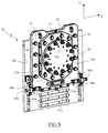
- the rear face of the test vehicle 12 is provided with a device interface 35, as shown in FIG. 9, on which the end of the push rod 21 of launcher 2, this interface device 35 comprising means to adjust the coaxiality of the push rod 21 relative to the tube launch 20.
- the interface device 35 comprises a base 30 made integral with the vehicle 12 by being for example fixed on the wall vertical rear of the test vehicle 12.
- This base 30 supports a first plate adjustment 31 which is immobilized on the base 30 by means of fixing screws 16, these fixing screws passing through the first plate 31 by oblong holes allowing a displacement along the X axis of the first plate 31 relative to the base 30 when the fixing screws 16 are not tightened.
- the base 30 has a width greater than the width of the first plate 31 and supports laterally, of each side of the first plate 31, a cleat 30a comprising a threaded bore according to the X axis provided with an adjustment screw 30b, the latter having one end bearing against a stop 31a carried by the first plate 31, the two tabs 30a allowing precise positioning along the X axis of the first plate 31 by relative to the base 30 before it is immobilized by tightening the fixing screws 16.
- the first adjustment plate 31 supports meanwhile a second adjustment plate 32 of reduced size compared to the dimensions of the first adjustment plate 31, this second plate 32 being immobilized on the first plate 31 by means of fixing screws 17 passing through oblong holes in the second plate 32 and coming to be screwed into threaded bores of the first plate 31 provided for this purpose, the oblong holes of the second plate 32 allowing a displacement along the Y axis of the second adjustment plate 32 relative to the first plate 31 when the fixing screws 17 are not tightened.
- the first one plate 31 also includes on each side of the second plate 32 rules 31b guiding the second plate 32 onto the next first plate 31 the Y axis by preventing any movement along the X axis.
- the first plate 31 finally comprises opposite the lower part of the second plate 32 a cleat 31c comprising a threaded bore along the Y axis provided with an adjustment screw, the end presses on the lower edge of the first plate 31 and allows its precise positioning along the Y axis before immobilization by tightening the screws fasteners 17.
- the second plate 32 has in its center a support disc 33 which is fixed directly on the end of the push rod 21, this disc having a periphery spherical cooperating with an opening of complementary shape formed in the second plate 32, thus providing a ball joint allowing rotation of the plane of the disc 33 relative to the plane of the second plate 32.
- the second plate 32 includes a clamping screw making it possible to block the movement of rotation of the disc 33 relative to the second plate 32.
- the centering of the rod thrust 21 on the support disc 33 is produced by means of multiple tenons 33a distributed along the edge of the disc 33 and fitting into holes at the end of the push rod 21, the final immobilization being carried out by means of screws fixing through disc holes 33 and screwing into threaded bores provided for this purpose on the end of the push rod 21.
- the interface device 35 thus produced enables the vehicle 12 to be made integral with propel the push rod 21 of the test device while allowing the adjustment of the coaxiality of the push rod 21 with the launching tube 20, perfect coaxiality being essential for obtaining an optimal thrust without risk of deterioration of the test device.
- FIG. 5 represents another configuration of use of the testing device according to the invention in which the pyrotechnic launcher 2 is used as a catapult to propel with an energy of 6 MJ, a test vehicle 12 weighing around 55 t on an obstacle 40 arranged on the track.
- the launcher pyrotechnic 2 is placed slightly higher than in the previous configuration so that the push rod 21 is always substantially aligned with the center of gravity of the test vehicle 12.
- the front face of the test vehicle 12 is provided with an absorbing element of energy 14 to be tested and the rear face of the vehicle 12 is connected to the push rod 21 via the interface device 35 previously described.
- this type test well 4 can advantageously be equipped with a camera against diving allowing to film from below the deformations during the impact.
- FIG. 6 represents yet another configuration for using the device according to the invention in which the pyrotechnic launcher 2 is used with a propulsion of the push rod 21 according to a programmed acceleration.
- a test vehicle 12 supporting an energy absorbing element 14 is attached to another vehicle 13, the energy absorbing element being interposed between the two vehicles 12 and 13. All of these two vehicles 12 and 13 are taken into account.
- the thrust rod 21 is arranged at the height of the rigid chassis of vehicles 12 and 13.
- FIG. 7 represents a configuration in which the pyrotechnic launcher 2 is used as a static press to subject a structure to different stresses railway vehicle.
- the vehicle 12 to be tested is taken sandwich between a metal structure 18 fixed on the concrete slab 1 and the rod of thrust 21 of the pyrotechnic launcher 2.
- the thrust rod is preferably placed at the height of the rigid chassis of the vehicle 12 but little vary depending on the purpose of the tests performed.
- FIG. 8 represents a configuration preferably used for the test of low capacity energy absorbers.
- the pyrotechnic launcher 2 will be lowered into the pit 4 so that the axis of the tube launch 20 is at the height of the launch carriage 5.
- the element energy absorber 15 to be tested is located at the end of the pit 4 in the axis of the carriage 5 so that the carriage catapulted by the pyrotechnic launcher 2 strike the energy absorbing element 15.
- the launching carriage 5 may be used alone or be propelled by being rigidly connected by its lashing ring 51 to a small vehicle resting on the rails of the railway track 3 so as to increase the mass striking the energy absorber 15.
- the launching cart 5 can also be used to tow, by means of the lashing ring 51, a light vehicle, automotive type, for example to perform crash tests.
- Such a device therefore makes it possible to perform mechanical tests, in particular for test the resistance of energy absorbing elements in the railway sector, on a large power range thanks to the pyrotechnic launcher and following numerous configurations thanks to the height adjustment of the pyrotechnic launcher.
- immobilization of the pyrotechnic launcher against the recoil effect by an element bumper on its rear part which simultaneously ensures parallelism between the tube launch and the track allows to maintain an excellent parallelism of the tube launch with the railway during the shots since the recoil effect tends to put in support the support surfaces which ensure parallelism.
- the good performance of the parallelism between the launch tube and the railway track during shots is reinforced by the fact that the stop element and the gantry supporting the pyrotechnic launcher as well as the railway are integral with the same concrete slab.
Landscapes
- Physics & Mathematics (AREA)
- General Physics & Mathematics (AREA)
- Engineering & Computer Science (AREA)
- Mechanical Engineering (AREA)
- Investigating Strength Of Materials By Application Of Mechanical Stress (AREA)
- Testing Of Devices, Machine Parts, Or Other Structures Thereof (AREA)
- Braking Arrangements (AREA)
- Vibration Dampers (AREA)
- Bridges Or Land Bridges (AREA)
Abstract
Description
- l'élément butoir et l'élément support reposent sur une dalle de béton, cette dernière supportant également une partie de la portion de voie ferrée ;
- la dalle de béton est ancrée dans le sol au moyen de pieux d'ancrage plantés dans le sol et noyés partiellement dans la dalle de béton ;
- la dalle de béton comporte une fosse s'étendant entre les rails de la voie ferrée, la fosse recevant un chariot de lancement coulissant entre les rails et pouvant être propulsé par la tige de poussée ;
- les moyens de fixation du lanceur pyrotechnique sur l'élément support et l'élément butoir permettent de descendre le lanceur pyrotechnique sous le niveau des rails de la voie ferrée et la fosse présente une paroi faisant face au lanceur pyrotechnique pouvant recevoir un élément absorbeur d'énergie sur lequel vient buter le chariot de lancement ;
- l'élément support est un portique comprenant deux éléments verticaux munis de multiples trous permettant la fixation à différentes hauteurs de pattes supportant un anneau entourant le tube de lancement, l'anneau pouvant pivoter sur les pattes suivant un axe horizontal perpendiculaire à l'axe du tube de lancement ;
- l'élément butoir est constitué d'un bloc de béton comportant une paroi sensiblement verticale sur laquelle est fixée une plaque de fixation disposée parfaitement perpendiculairement au plan des rails de la voie ferrée, la plaque fixation comportant de multiples trous permettant la fixation à différentes hauteurs d'une chaise d'appui à l'extrémité de laquelle est fixé l'extrémité arrière du lanceur pyrotechnique ;
- la tige de poussée est supportée directement par le véhicule au moyen d'un dispositif interface muni de moyens de réglage de la coaxialité de la tige de poussée par rapport au tube de lancement.
- la figure 1 est une vue en perspective d'un dispositif pour la réalisation d'essais mécaniques sur des éléments absorbeurs d'énergie selon un mode particulier de réalisation de l'invention ;
- la figure 2 est une vue de détail, en perspective, du portique supportant, dans sa partie centrale, le lanceur pyrotechnique du dispositif de la figure 1 ;
- la figure 3 est une vue de détail, en perspective, de l'élément butoir assurant l'immobilisation axiale du lanceur pyrotechnique de la figure 1 ;
- les figures 4 à 8 sont des vues représentant schématiquement l'utilisation du dispositif selon l'invention pour la réalisation de différents essais mécaniques ;
- la figure 9 est une vue en perspective du dispositif interface réalisant la liaison entre le véhicule et la tige de poussée du dispositif d'essais selon l'invention.
Claims (8)
- Dispositif pour la réalisation d'essais mécaniques sur des structures, notamment des éléments absorbeur d'énergie (14,15) du domaine ferroviaire, caractérisé en qu'un lanceur pyrotechnique (2) comportant un tube de lancement (20) dans lequel coulisse une tige de poussée (21) est disposé à une extrémité d'une portion de voie ferrée (3), ledit lanceur pyrotechnique (2) étant supporté dans sa partie centrale par un élément support (7) et étant bloqué vers l'arrière par un élément butoir (8) disposé derrière le lanceur pyrotechnique (2), ledit élément support (7) et ledit élément butoir (8) comportant des moyens de fixation permettant le maintien dudit lanceur pyrotechnique (2) à différentes hauteurs par rapport aux rails de la voie ferrée (3).
- Dispositif selon la revendication 1, caractérisé en ce que ledit élément butoir (8) et ledit élément support (7) reposent sur une dalle de béton (1), ladite dalle de béton (1) supportant également une partie de la portion de voie ferrée (3).
- Dispositif selon la revendication 2, caractérisé en ce que ladite dalle de béton (1) est ancrée dans le sol au moyen de pieux d'ancrage (11) plantés dans le sol et noyés partiellement dans ladite dalle de béton (1).
- Dispositif selon l'une quelconque des revendications 2 à 3, caractérisé en ce que ladite dalle de béton (1) comporte une fosse (4) s'étendant entre les rails de la voie ferrée (3), ladite fosse (4) recevant un chariot de lancement (5) coulissant entre les rails et pouvant être propulsé par la tige de poussée (21).
- Dispositif selon la revendication 4, caractérisé en ce que les moyens de fixation du lanceur pyrotechnique (2) sur l'élément support (7) et l'élément butoir (8) permettent de descendre le lanceur pyrotechnique (2) sous le niveau des rails de la voie ferrée (3) et en ce que ladite fosse (4) présente une paroi faisant face au lanceur pyrotechnique (2) pouvant recevoir un élément absorbeur d'énergie (15) à tester sur lequel vient buter ledit chariot de lancement (5).
- Dispositif selon l'une quelconque des revendications 1 à 5, caractérisé en ce que ledit élément support (7) est un portique comprenant deux éléments verticaux (71) munis de multiples trous permettant la fixation à différentes hauteurs de pattes (72) supportant un anneau (73)entourant le tube de lancement (20), ledit anneau (73) pouvant pivoter sur lesdites pattes (72) suivant un axe horizontal perpendiculaire à l'axe du tube de lancement (20).
- Dispositif selon l'une quelconque des revendications 1 à 6, caractérisé en ce que ledit élément butoir (8) est constitué d'un bloc de béton comportant une paroi sensiblement verticale (8a) sur laquelle est fixée une plaque de fixation (81) disposée parfaitement perpendiculairement au plan des rails de la voie ferrée (3), ladite plaque fixation (81) comportant de multiples trous permettant la fixation à différentes hauteurs d'une chaise d'appui (9) à l'extrémité de laquelle est fixée l'extrémité arrière du lanceur pyrotechnique (2).
- Dispositif selon l'une quelconque des revendications 1 à 7, caractérisé en ce que la tige de poussée (21) est supportée directement par un véhicule (12) au moyen d'un dispositif interface (35) muni de moyens de réglage de la coaxialité de la tige de poussée (21) par rapport au tube de lancement (20).
Applications Claiming Priority (2)
| Application Number | Priority Date | Filing Date | Title |
|---|---|---|---|
| FR0114650A FR2832217B1 (fr) | 2001-11-13 | 2001-11-13 | Dispositif pour la realisation d'essais mecaniques sur des structures |
| FR0114650 | 2001-11-13 |
Publications (2)
| Publication Number | Publication Date |
|---|---|
| EP1312909A1 true EP1312909A1 (fr) | 2003-05-21 |
| EP1312909B1 EP1312909B1 (fr) | 2004-06-16 |
Family
ID=8869330
Family Applications (1)
| Application Number | Title | Priority Date | Filing Date |
|---|---|---|---|
| EP02292779A Expired - Lifetime EP1312909B1 (fr) | 2001-11-13 | 2002-11-07 | Dispositif pour la réalisation d'essais mécaniques sur des structures ( ferroviaire, lanceur pyrotechnique réglable, voie ferrée ) |
Country Status (7)
| Country | Link |
|---|---|
| US (1) | US6739175B2 (fr) |
| EP (1) | EP1312909B1 (fr) |
| AT (1) | ATE269537T1 (fr) |
| CA (1) | CA2411681C (fr) |
| DE (1) | DE60200646T2 (fr) |
| ES (1) | ES2220884T3 (fr) |
| FR (1) | FR2832217B1 (fr) |
Cited By (1)
| Publication number | Priority date | Publication date | Assignee | Title |
|---|---|---|---|---|
| CN112798210A (zh) * | 2021-04-14 | 2021-05-14 | 西南交通大学 | 一种电动悬浮磁浮列车振动试验台及其试验方法 |
Families Citing this family (22)
| Publication number | Priority date | Publication date | Assignee | Title |
|---|---|---|---|---|
| WO2005010478A1 (fr) * | 2003-07-23 | 2005-02-03 | Mts Systems Corporation | Element de force pour simulateur de collision de vehicule |
| DE10339409B3 (de) * | 2003-08-27 | 2004-10-07 | Opel Eisenach Gmbh | Abschussvorrichtung zum Beschleunigen eines Prüfkörpers |
| DE102005039966B3 (de) * | 2005-08-24 | 2007-03-22 | TÜV Kraftfahrt GmbH - TÜV Rheinland Group | Prüfvorrichtung |
| CN100545617C (zh) * | 2006-05-23 | 2009-09-30 | 比亚迪股份有限公司 | 加速度模拟台 |
| CN101498622B (zh) * | 2008-12-25 | 2014-01-01 | 中南大学 | 列车气动性能模拟动模型试验方法及其装置 |
| CN101441137B (zh) * | 2009-01-07 | 2011-01-26 | 中南大学 | 列车气动性能模拟动模型试验制动方法及其制动装置 |
| DE102009038455A1 (de) * | 2009-08-21 | 2011-02-24 | GM Global Technology Operations, Inc., Detroit | Verfahren zum Betrieb einer Crashsimulationseinrichtung, Zusatzvorrichtung für eine Crashsimulationseinrichtung und Crashsimulationseinrichtung mit einer solchen Zusatzvorrichtung |
| JP5429152B2 (ja) * | 2010-12-24 | 2014-02-26 | イオ インダストリー株式会社 | ドアハンドル試験装置 |
| ES2392066B1 (es) * | 2011-02-04 | 2013-10-16 | Seat, S.A. | Sistema para ensayo de resistencia al impacto de portaequipajes de techo en vehículos. |
| CN102416969B (zh) * | 2011-10-17 | 2014-03-19 | 株洲南车时代电气股份有限公司 | 一种夹轨器和一种机车牵引定位系统 |
| CN103698138A (zh) * | 2013-11-29 | 2014-04-02 | 南车青岛四方机车车辆股份有限公司 | 轨道车辆编组试验的车辆固定装置 |
| CN105258901A (zh) * | 2015-11-03 | 2016-01-20 | 南车青岛四方机车车辆股份有限公司 | 一种轨道车辆碰撞试验的防护装置和防护方法 |
| CN107421705B (zh) * | 2017-06-02 | 2023-06-30 | 南京理工大学 | 一种测量缓冲器抗冲击性能的质量可调式实验装置 |
| CN107727410B (zh) * | 2017-10-26 | 2023-10-31 | 山东海诺知识产权运营管理有限公司 | 一种推车式灭火器行驶性能测试装置 |
| CN109269820B (zh) * | 2018-10-17 | 2024-04-19 | 中国人民解放军63921部队 | 一种大型高能缓冲器的试验系统 |
| CN111366373B (zh) * | 2019-03-20 | 2024-07-02 | 襄阳达安汽车检测中心有限公司 | 商用车驾驶室侧面斜20°冲击试验台 |
| CN112197982A (zh) * | 2019-07-08 | 2021-01-08 | 中车长春轨道客车股份有限公司 | 重心可调式高铁模拟碰撞车体及包括该车体的碰撞车 |
| CN110361200B (zh) * | 2019-07-12 | 2021-11-05 | 中国汽车技术研究中心有限公司 | 一种模拟汽车侧面柱碰撞的台车实现与参数获取方法 |
| CN110470492B (zh) * | 2019-08-02 | 2021-01-01 | 中国科学院力学研究所 | 一种动模型实验装置及拖车气动加减速方法 |
| CN110987478B (zh) * | 2019-12-30 | 2021-06-01 | 烟台辰宇汽车部件有限公司 | 一种推力杆试验机 |
| CN114813404B (zh) * | 2022-06-28 | 2022-09-06 | 徐州阳森建设科技有限公司 | 一种太阳能板的抗变形能力测试装置 |
| CN118817287B (zh) * | 2024-09-14 | 2024-12-13 | 齐鲁工业大学(山东省科学院) | 一种用于稳固深海舰船的系泊链疲劳试验装置及其应用 |
Citations (4)
| Publication number | Priority date | Publication date | Assignee | Title |
|---|---|---|---|---|
| SU1658006A1 (ru) * | 1989-05-29 | 1991-06-23 | Центральное Проектно-Конструкторское И Технологическое Бюро Промышленного Транспорта Черной Металлургии | Стенд дл испытани рельсовых транспортных средств |
| US5325700A (en) * | 1993-04-13 | 1994-07-05 | Emerald Hydraulics, Inc. | Railcar cushion device tester and method |
| JPH08240509A (ja) * | 1995-03-01 | 1996-09-17 | Mitsubishi Motors Corp | 車両の衝突試験装置 |
| FR2765685A1 (fr) * | 1997-07-03 | 1999-01-08 | Bernard Castagner | Banc pyrotechnique de realisation d'acceleration et de deceleration a spectres simples ou complexes |
Family Cites Families (6)
| Publication number | Priority date | Publication date | Assignee | Title |
|---|---|---|---|---|
| FR2234171B1 (fr) * | 1973-06-22 | 1976-04-30 | Bulgarski Darjavni Schelesniei | |
| IT1261307B (it) * | 1993-06-22 | 1996-05-14 | Fiat Auto Spa | Apparecchiatura, procedimento e struttura-modello riutilizzabile per effettuare prove d'impatto su elementi componenti di veicoli. |
| US5485742A (en) * | 1994-08-24 | 1996-01-23 | Emerald Hydraulics, Inc. | Test sill for railcar cushion units |
| DE19529801C1 (de) * | 1995-08-14 | 1996-07-18 | Ford Werke Ag | Vorrichtung zur Durchführung eines Crashtests bei einem Fahrzeug |
| US5623094A (en) * | 1996-01-17 | 1997-04-22 | Mga Research Corporation | Sled testing system |
| US6422058B1 (en) * | 2000-08-04 | 2002-07-23 | J. Edgar Myles | Railroad car coupling simulator and method |
-
2001
- 2001-11-13 FR FR0114650A patent/FR2832217B1/fr not_active Expired - Lifetime
-
2002
- 2002-11-07 DE DE60200646T patent/DE60200646T2/de not_active Expired - Lifetime
- 2002-11-07 EP EP02292779A patent/EP1312909B1/fr not_active Expired - Lifetime
- 2002-11-07 ES ES02292779T patent/ES2220884T3/es not_active Expired - Lifetime
- 2002-11-07 AT AT02292779T patent/ATE269537T1/de active
- 2002-11-08 US US10/290,321 patent/US6739175B2/en not_active Expired - Lifetime
- 2002-11-12 CA CA002411681A patent/CA2411681C/fr not_active Expired - Lifetime
Patent Citations (4)
| Publication number | Priority date | Publication date | Assignee | Title |
|---|---|---|---|---|
| SU1658006A1 (ru) * | 1989-05-29 | 1991-06-23 | Центральное Проектно-Конструкторское И Технологическое Бюро Промышленного Транспорта Черной Металлургии | Стенд дл испытани рельсовых транспортных средств |
| US5325700A (en) * | 1993-04-13 | 1994-07-05 | Emerald Hydraulics, Inc. | Railcar cushion device tester and method |
| JPH08240509A (ja) * | 1995-03-01 | 1996-09-17 | Mitsubishi Motors Corp | 車両の衝突試験装置 |
| FR2765685A1 (fr) * | 1997-07-03 | 1999-01-08 | Bernard Castagner | Banc pyrotechnique de realisation d'acceleration et de deceleration a spectres simples ou complexes |
Non-Patent Citations (2)
| Title |
|---|
| DATABASE WPI Section EI Week 199212, Derwent World Patents Index; Class R15, AN 1992-095445, XP002211257 * |
| PATENT ABSTRACTS OF JAPAN vol. 1997, no. 01 31 January 1997 (1997-01-31) * |
Cited By (3)
| Publication number | Priority date | Publication date | Assignee | Title |
|---|---|---|---|---|
| CN112798210A (zh) * | 2021-04-14 | 2021-05-14 | 西南交通大学 | 一种电动悬浮磁浮列车振动试验台及其试验方法 |
| CN112798210B (zh) * | 2021-04-14 | 2021-08-31 | 西南交通大学 | 一种电动悬浮磁浮列车振动试验台及其试验方法 |
| US11366038B1 (en) | 2021-04-14 | 2022-06-21 | Southwest Jiaotong University | Vibration test bench for electrodynamic-suspension magnetic levitation (maglev) trains and testing method using same |
Also Published As
| Publication number | Publication date |
|---|---|
| CA2411681C (fr) | 2009-03-10 |
| EP1312909B1 (fr) | 2004-06-16 |
| CA2411681A1 (fr) | 2003-05-13 |
| ATE269537T1 (de) | 2004-07-15 |
| ES2220884T3 (es) | 2004-12-16 |
| US20030089268A1 (en) | 2003-05-15 |
| DE60200646D1 (de) | 2004-07-22 |
| FR2832217B1 (fr) | 2004-10-01 |
| US6739175B2 (en) | 2004-05-25 |
| DE60200646T2 (de) | 2005-07-07 |
| FR2832217A1 (fr) | 2003-05-16 |
Similar Documents
| Publication | Publication Date | Title |
|---|---|---|
| EP1312909B1 (fr) | Dispositif pour la réalisation d'essais mécaniques sur des structures ( ferroviaire, lanceur pyrotechnique réglable, voie ferrée ) | |
| CA2649218C (fr) | Plancher d'aeronef, utilisation d'un tel plancher et troncon d'aeronef muni d'un tel plancher | |
| WO2005003587A1 (fr) | Element de structure pour vehicule destine a amortir certains chocs par deformation plastique | |
| FR2997500A1 (fr) | Banc d'essais pour vehicule automobile | |
| CA3038877A1 (fr) | Satellite comprenant un instrument optique de prise de vue | |
| FR2867766A1 (fr) | Installation pour le transfert de charge entre une plate-forme de transfert et un vehicule de transport | |
| FR2775240A1 (fr) | Perfectionnement aux tampons amortisseurs d'accostage pour vehicules ferroviaires | |
| EP0222678B1 (fr) | Unité mobile de tir au mortier | |
| EP2539571A2 (fr) | Banc d'essais pour moteur à reaction | |
| WO2010139617A1 (fr) | Système d'atterrissage d'un corps et sonde spatiale équipée d'un tel système | |
| EP3825180B1 (fr) | Dispositif de partitionnement pour véhicule frigorifique | |
| FR2780381A1 (fr) | Catapulte pour le lancement d'un corps volant | |
| FR2841883A1 (fr) | Butoir pour quai | |
| FR3138117A1 (fr) | Ensemble propulsif à hélice pour aéronef | |
| FR3004529A1 (fr) | Dispositif de support de tourelleau | |
| EP0275782B1 (fr) | Dispositif perfectionné pour engendrer dans le sol à la fois des ondes acoustiques transversales et longitudinales suivant une pluralité de directions différentes | |
| EP1535804B1 (fr) | Dispositif contre les chocs pour véhicule automobile comprenant des éléments amortisseurs de chocs | |
| BE1013240A6 (fr) | Dispositif de support pour rail de voie ferree. | |
| FR3102555A1 (fr) | Simulateur de collision pour véhicule automobile | |
| EP1472132A1 (fr) | Structure pour vehicule automobile et vehicule equipe d' une telle structure | |
| FR2571975A1 (fr) | Dispositif d'entrainement pour joueurs de ballons. | |
| WO2022171544A1 (fr) | Agencement comprenant un chargeur, un bloc moteur, des longerons et un dispositif de fixation | |
| FR3128932A1 (fr) | Renfort mécanique pour support de fixation arrière d’un berceau moteur | |
| FR2698429A1 (fr) | Glissière perfectionnée et tiroir comportant au moins une telle glissière. | |
| FR2977596A1 (fr) | Base modulaire pour hydrolienne |
Legal Events
| Date | Code | Title | Description |
|---|---|---|---|
| PUAI | Public reference made under article 153(3) epc to a published international application that has entered the european phase |
Free format text: ORIGINAL CODE: 0009012 |
|
| AK | Designated contracting states |
Designated state(s): AT BE BG CH CY CZ DE DK EE ES FI FR GB GR IE IT LI LU MC NL PT SE SK TR |
|
| AX | Request for extension of the european patent |
Extension state: AL LT LV MK RO SI |
|
| GRAP | Despatch of communication of intention to grant a patent |
Free format text: ORIGINAL CODE: EPIDOSNIGR1 |
|
| 17P | Request for examination filed |
Effective date: 20031017 |
|
| RTI1 | Title (correction) |
Free format text: DEVICE FOR MECHANICAL TESTS ON STRUCTURES ( RAILWAY, ADJUSTABLE PYROTECHNICAL PISTON, RAILS ) |
|
| AKX | Designation fees paid |
Designated state(s): AT BE BG CH CY CZ DE DK EE ES FI FR GB GR IE IT LI LU MC NL PT SE SK TR |
|
| GRAS | Grant fee paid |
Free format text: ORIGINAL CODE: EPIDOSNIGR3 |
|
| GRAA | (expected) grant |
Free format text: ORIGINAL CODE: 0009210 |
|
| AK | Designated contracting states |
Kind code of ref document: B1 Designated state(s): AT BE BG CH CY CZ DE DK EE ES FI FR GB GR IE IT LI LU MC NL PT SE SK TR |
|
| PG25 | Lapsed in a contracting state [announced via postgrant information from national office to epo] |
Ref country code: IE Free format text: LAPSE BECAUSE OF FAILURE TO SUBMIT A TRANSLATION OF THE DESCRIPTION OR TO PAY THE FEE WITHIN THE PRESCRIBED TIME-LIMIT Effective date: 20040616 Ref country code: CZ Free format text: LAPSE BECAUSE OF FAILURE TO SUBMIT A TRANSLATION OF THE DESCRIPTION OR TO PAY THE FEE WITHIN THE PRESCRIBED TIME-LIMIT Effective date: 20040616 Ref country code: TR Free format text: LAPSE BECAUSE OF FAILURE TO SUBMIT A TRANSLATION OF THE DESCRIPTION OR TO PAY THE FEE WITHIN THE PRESCRIBED TIME-LIMIT Effective date: 20040616 Ref country code: SK Free format text: LAPSE BECAUSE OF FAILURE TO SUBMIT A TRANSLATION OF THE DESCRIPTION OR TO PAY THE FEE WITHIN THE PRESCRIBED TIME-LIMIT Effective date: 20040616 Ref country code: EE Free format text: LAPSE BECAUSE OF FAILURE TO SUBMIT A TRANSLATION OF THE DESCRIPTION OR TO PAY THE FEE WITHIN THE PRESCRIBED TIME-LIMIT Effective date: 20040616 Ref country code: CY Free format text: LAPSE BECAUSE OF FAILURE TO SUBMIT A TRANSLATION OF THE DESCRIPTION OR TO PAY THE FEE WITHIN THE PRESCRIBED TIME-LIMIT Effective date: 20040616 Ref country code: FI Free format text: LAPSE BECAUSE OF FAILURE TO SUBMIT A TRANSLATION OF THE DESCRIPTION OR TO PAY THE FEE WITHIN THE PRESCRIBED TIME-LIMIT Effective date: 20040616 Ref country code: BG Free format text: LAPSE BECAUSE OF FAILURE TO SUBMIT A TRANSLATION OF THE DESCRIPTION OR TO PAY THE FEE WITHIN THE PRESCRIBED TIME-LIMIT Effective date: 20040616 |
|
| REG | Reference to a national code |
Ref country code: GB Ref legal event code: FG4D Free format text: NOT ENGLISH |
|
| REG | Reference to a national code |
Ref country code: CH Ref legal event code: EP |
|
| REF | Corresponds to: |
Ref document number: 60200646 Country of ref document: DE Date of ref document: 20040722 Kind code of ref document: P |
|
| REG | Reference to a national code |
Ref country code: IE Ref legal event code: FG4D Free format text: FRENCH |
|
| REG | Reference to a national code |
Ref country code: CH Ref legal event code: NV Representative=s name: CABINET ROLAND NITHARDT CONSEILS EN PROPRIETE INDU |
|
| GBT | Gb: translation of ep patent filed (gb section 77(6)(a)/1977) |
Effective date: 20040823 |
|
| PG25 | Lapsed in a contracting state [announced via postgrant information from national office to epo] |
Ref country code: SE Free format text: LAPSE BECAUSE OF FAILURE TO SUBMIT A TRANSLATION OF THE DESCRIPTION OR TO PAY THE FEE WITHIN THE PRESCRIBED TIME-LIMIT Effective date: 20040916 Ref country code: GR Free format text: LAPSE BECAUSE OF FAILURE TO SUBMIT A TRANSLATION OF THE DESCRIPTION OR TO PAY THE FEE WITHIN THE PRESCRIBED TIME-LIMIT Effective date: 20040916 Ref country code: DK Free format text: LAPSE BECAUSE OF FAILURE TO SUBMIT A TRANSLATION OF THE DESCRIPTION OR TO PAY THE FEE WITHIN THE PRESCRIBED TIME-LIMIT Effective date: 20040916 |
|
| PG25 | Lapsed in a contracting state [announced via postgrant information from national office to epo] |
Ref country code: MC Free format text: LAPSE BECAUSE OF NON-PAYMENT OF DUE FEES Effective date: 20041130 |
|
| REG | Reference to a national code |
Ref country code: ES Ref legal event code: FG2A Ref document number: 2220884 Country of ref document: ES Kind code of ref document: T3 |
|
| REG | Reference to a national code |
Ref country code: IE Ref legal event code: FD4D |
|
| PLBE | No opposition filed within time limit |
Free format text: ORIGINAL CODE: 0009261 |
|
| STAA | Information on the status of an ep patent application or granted ep patent |
Free format text: STATUS: NO OPPOSITION FILED WITHIN TIME LIMIT |
|
| 26N | No opposition filed |
Effective date: 20050317 |
|
| PG25 | Lapsed in a contracting state [announced via postgrant information from national office to epo] |
Ref country code: FR Free format text: LAPSE BECAUSE OF NON-PAYMENT OF DUE FEES Effective date: 20050729 |
|
| REG | Reference to a national code |
Ref country code: FR Ref legal event code: ST |
|
| PG25 | Lapsed in a contracting state [announced via postgrant information from national office to epo] |
Ref country code: PT Free format text: LAPSE BECAUSE OF NON-PAYMENT OF DUE FEES Effective date: 20041116 |
|
| REG | Reference to a national code |
Ref country code: CH Ref legal event code: PUE Owner name: ALSTOM TRANSPORT SA, FR Free format text: FORMER OWNER: ALSTOM, FR |
|
| REG | Reference to a national code |
Ref country code: CH Ref legal event code: PUE Owner name: ALSTOM TRANSPORT TECHNOLOGIES, FR Free format text: FORMER OWNER: ALSTOM TRANSPORT SA, FR |
|
| REG | Reference to a national code |
Ref country code: ES Ref legal event code: PC2A Owner name: ALSTOM TRANSPORT SA Effective date: 20140211 |
|
| REG | Reference to a national code |
Ref country code: GB Ref legal event code: 732E Free format text: REGISTERED BETWEEN 20140123 AND 20140129 |
|
| BECH | Be: change of holder |
Owner name: ALSTOM TRANSPORT TECHNOLOGIES Effective date: 20140217 |
|
| REG | Reference to a national code |
Ref country code: NL Ref legal event code: SD Effective date: 20140226 |
|
| REG | Reference to a national code |
Ref country code: DE Ref legal event code: R082 Ref document number: 60200646 Country of ref document: DE Representative=s name: LAVOIX MUNICH, DE |
|
| REG | Reference to a national code |
Ref country code: DE Ref legal event code: R082 Ref document number: 60200646 Country of ref document: DE Representative=s name: LAVOIX MUNICH, DE Effective date: 20140416 Ref country code: DE Ref legal event code: R081 Ref document number: 60200646 Country of ref document: DE Owner name: SPEEDINNOV, FR Free format text: FORMER OWNER: ALSTOM, PARIS, FR Effective date: 20140416 Ref country code: DE Ref legal event code: R081 Ref document number: 60200646 Country of ref document: DE Owner name: ALSTOM TRANSPORT TECHNOLOGIES, FR Free format text: FORMER OWNER: ALSTOM, PARIS, FR Effective date: 20140416 |
|
| REG | Reference to a national code |
Ref country code: CH Ref legal event code: NV Representative=s name: CABINET ROLAND NITHARDT CONSEILS EN PROPRIETE , CH |
|
| REG | Reference to a national code |
Ref country code: AT Ref legal event code: PC Ref document number: 269537 Country of ref document: AT Kind code of ref document: T Owner name: ALSTOM TRANSPORT TECHNOLOGIES, FR Effective date: 20140919 |
|
| REG | Reference to a national code |
Ref country code: DE Ref legal event code: R082 Ref document number: 60200646 Country of ref document: DE Representative=s name: LAVOIX MUNICH, DE Ref country code: DE Ref legal event code: R081 Ref document number: 60200646 Country of ref document: DE Owner name: SPEEDINNOV, FR Free format text: FORMER OWNER: ALSTOM TRANSPORT TECHNOLOGIES, LEVALLOIS-PERRET, FR |
|
| REG | Reference to a national code |
Ref country code: CH Ref legal event code: PUE Owner name: SPEEDINNOV SOCIETE PAR ACTIONS SIMPLIFIEE, FR Free format text: FORMER OWNER: ALSTOM TRANSPORT TECHNOLOGIES, FR |
|
| REG | Reference to a national code |
Ref country code: LU Ref legal event code: PD Owner name: SPEEDINNOV; FR Free format text: FORMER OWNER: ALSTOM TRANSPORT TECHNOLOGIES Effective date: 20170519 |
|
| REG | Reference to a national code |
Ref country code: GB Ref legal event code: 732E Free format text: REGISTERED BETWEEN 20170629 AND 20170705 |
|
| REG | Reference to a national code |
Ref country code: NL Ref legal event code: PD Owner name: SPEEDLNNOV; FR Free format text: DETAILS ASSIGNMENT: CHANGE OF OWNER(S), ASSIGNMENT; FORMER OWNER NAME: ALSTOM TRANSPORT TECHNOLOGIES Effective date: 20170510 |
|
| REG | Reference to a national code |
Ref country code: ES Ref legal event code: PC2A Owner name: SPEEDINNOV Effective date: 20171027 |
|
| REG | Reference to a national code |
Ref country code: AT Ref legal event code: PC Ref document number: 269537 Country of ref document: AT Kind code of ref document: T Owner name: SPEEDINNOV, FR Effective date: 20180221 |
|
| PGFP | Annual fee paid to national office [announced via postgrant information from national office to epo] |
Ref country code: LU Payment date: 20211119 Year of fee payment: 20 |
|
| PGFP | Annual fee paid to national office [announced via postgrant information from national office to epo] |
Ref country code: NL Payment date: 20211118 Year of fee payment: 20 Ref country code: GB Payment date: 20211118 Year of fee payment: 20 Ref country code: DE Payment date: 20211118 Year of fee payment: 20 Ref country code: AT Payment date: 20211119 Year of fee payment: 20 |
|
| PGFP | Annual fee paid to national office [announced via postgrant information from national office to epo] |
Ref country code: IT Payment date: 20211119 Year of fee payment: 20 Ref country code: CH Payment date: 20211119 Year of fee payment: 20 Ref country code: BE Payment date: 20211118 Year of fee payment: 20 |
|
| PGFP | Annual fee paid to national office [announced via postgrant information from national office to epo] |
Ref country code: ES Payment date: 20220121 Year of fee payment: 20 |
|
| REG | Reference to a national code |
Ref country code: DE Ref legal event code: R071 Ref document number: 60200646 Country of ref document: DE |
|
| REG | Reference to a national code |
Ref country code: NL Ref legal event code: MK Effective date: 20221106 |
|
| REG | Reference to a national code |
Ref country code: CH Ref legal event code: PL |
|
| REG | Reference to a national code |
Ref country code: ES Ref legal event code: FD2A Effective date: 20221125 |
|
| REG | Reference to a national code |
Ref country code: GB Ref legal event code: PE20 Expiry date: 20221106 |
|
| REG | Reference to a national code |
Ref country code: BE Ref legal event code: MK Effective date: 20221107 |
|
| REG | Reference to a national code |
Ref country code: AT Ref legal event code: MK07 Ref document number: 269537 Country of ref document: AT Kind code of ref document: T Effective date: 20221107 |
|
| PG25 | Lapsed in a contracting state [announced via postgrant information from national office to epo] |
Ref country code: GB Free format text: LAPSE BECAUSE OF EXPIRATION OF PROTECTION Effective date: 20221106 Ref country code: ES Free format text: LAPSE BECAUSE OF EXPIRATION OF PROTECTION Effective date: 20221108 |