EP1309827B1 - Tieftemperaturluftzerlegungsanlage - Google Patents
Tieftemperaturluftzerlegungsanlage Download PDFInfo
- Publication number
- EP1309827B1 EP1309827B1 EP01974179A EP01974179A EP1309827B1 EP 1309827 B1 EP1309827 B1 EP 1309827B1 EP 01974179 A EP01974179 A EP 01974179A EP 01974179 A EP01974179 A EP 01974179A EP 1309827 B1 EP1309827 B1 EP 1309827B1
- Authority
- EP
- European Patent Office
- Prior art keywords
- column
- box
- low
- pressure column
- temperature air
- Prior art date
- Legal status (The legal status is an assumption and is not a legal conclusion. Google has not performed a legal analysis and makes no representation as to the accuracy of the status listed.)
- Expired - Lifetime
Links
- 238000005194 fractionation Methods 0.000 title claims 14
- XKRFYHLGVUSROY-UHFFFAOYSA-N Argon Chemical compound [Ar] XKRFYHLGVUSROY-UHFFFAOYSA-N 0.000 claims abstract description 118
- 229910052786 argon Inorganic materials 0.000 claims abstract description 59
- 239000007788 liquid Substances 0.000 claims abstract description 16
- 238000010992 reflux Methods 0.000 claims abstract 3
- 238000009833 condensation Methods 0.000 claims description 4
- 230000005494 condensation Effects 0.000 claims description 4
- 238000000354 decomposition reaction Methods 0.000 abstract 1
- 238000004064 recycling Methods 0.000 abstract 1
- 238000000926 separation method Methods 0.000 description 13
- 239000003990 capacitor Substances 0.000 description 9
- 238000004519 manufacturing process Methods 0.000 description 8
- 230000008901 benefit Effects 0.000 description 6
- IJGRMHOSHXDMSA-UHFFFAOYSA-N Atomic nitrogen Chemical compound N#N IJGRMHOSHXDMSA-UHFFFAOYSA-N 0.000 description 4
- QVGXLLKOCUKJST-UHFFFAOYSA-N atomic oxygen Chemical compound [O] QVGXLLKOCUKJST-UHFFFAOYSA-N 0.000 description 4
- 239000001301 oxygen Substances 0.000 description 4
- 229910052760 oxygen Inorganic materials 0.000 description 4
- 230000002349 favourable effect Effects 0.000 description 3
- 238000007689 inspection Methods 0.000 description 3
- 230000009286 beneficial effect Effects 0.000 description 2
- 238000009826 distribution Methods 0.000 description 2
- 238000000034 method Methods 0.000 description 2
- 238000012986 modification Methods 0.000 description 2
- 230000004048 modification Effects 0.000 description 2
- 201000009240 nasopharyngitis Diseases 0.000 description 2
- 229910052757 nitrogen Inorganic materials 0.000 description 2
- 238000011084 recovery Methods 0.000 description 2
- OLBVUFHMDRJKTK-UHFFFAOYSA-N [N].[O] Chemical compound [N].[O] OLBVUFHMDRJKTK-UHFFFAOYSA-N 0.000 description 1
- 238000013459 approach Methods 0.000 description 1
- 238000013461 design Methods 0.000 description 1
- 238000010586 diagram Methods 0.000 description 1
- 239000012530 fluid Substances 0.000 description 1
- 239000007789 gas Substances 0.000 description 1
- 239000012774 insulation material Substances 0.000 description 1
- 238000005304 joining Methods 0.000 description 1
- 238000005259 measurement Methods 0.000 description 1
- DOTMOQHOJINYBL-UHFFFAOYSA-N molecular nitrogen;molecular oxygen Chemical compound N#N.O=O DOTMOQHOJINYBL-UHFFFAOYSA-N 0.000 description 1
- 238000005192 partition Methods 0.000 description 1
- 235000019362 perlite Nutrition 0.000 description 1
- 239000010451 perlite Substances 0.000 description 1
- 238000012360 testing method Methods 0.000 description 1
- 239000002699 waste material Substances 0.000 description 1
Images


Classifications
-
- F—MECHANICAL ENGINEERING; LIGHTING; HEATING; WEAPONS; BLASTING
- F25—REFRIGERATION OR COOLING; COMBINED HEATING AND REFRIGERATION SYSTEMS; HEAT PUMP SYSTEMS; MANUFACTURE OR STORAGE OF ICE; LIQUEFACTION SOLIDIFICATION OF GASES
- F25J—LIQUEFACTION, SOLIDIFICATION OR SEPARATION OF GASES OR GASEOUS OR LIQUEFIED GASEOUS MIXTURES BY PRESSURE AND COLD TREATMENT OR BY BRINGING THEM INTO THE SUPERCRITICAL STATE
- F25J3/00—Processes or apparatus for separating the constituents of gaseous or liquefied gaseous mixtures involving the use of liquefaction or solidification
- F25J3/02—Processes or apparatus for separating the constituents of gaseous or liquefied gaseous mixtures involving the use of liquefaction or solidification by rectification, i.e. by continuous interchange of heat and material between a vapour stream and a liquid stream
- F25J3/04—Processes or apparatus for separating the constituents of gaseous or liquefied gaseous mixtures involving the use of liquefaction or solidification by rectification, i.e. by continuous interchange of heat and material between a vapour stream and a liquid stream for air
-
- F—MECHANICAL ENGINEERING; LIGHTING; HEATING; WEAPONS; BLASTING
- F25—REFRIGERATION OR COOLING; COMBINED HEATING AND REFRIGERATION SYSTEMS; HEAT PUMP SYSTEMS; MANUFACTURE OR STORAGE OF ICE; LIQUEFACTION SOLIDIFICATION OF GASES
- F25J—LIQUEFACTION, SOLIDIFICATION OR SEPARATION OF GASES OR GASEOUS OR LIQUEFIED GASEOUS MIXTURES BY PRESSURE AND COLD TREATMENT OR BY BRINGING THEM INTO THE SUPERCRITICAL STATE
- F25J3/00—Processes or apparatus for separating the constituents of gaseous or liquefied gaseous mixtures involving the use of liquefaction or solidification
- F25J3/02—Processes or apparatus for separating the constituents of gaseous or liquefied gaseous mixtures involving the use of liquefaction or solidification by rectification, i.e. by continuous interchange of heat and material between a vapour stream and a liquid stream
- F25J3/04—Processes or apparatus for separating the constituents of gaseous or liquefied gaseous mixtures involving the use of liquefaction or solidification by rectification, i.e. by continuous interchange of heat and material between a vapour stream and a liquid stream for air
- F25J3/04763—Start-up or control of the process; Details of the apparatus used
- F25J3/04866—Construction and layout of air fractionation equipments, e.g. valves, machines
- F25J3/0489—Modularity and arrangement of parts of the air fractionation unit, in particular of the cold box, e.g. pre-fabrication, assembling and erection, dimensions, horizontal layout "plot"
-
- F—MECHANICAL ENGINEERING; LIGHTING; HEATING; WEAPONS; BLASTING
- F25—REFRIGERATION OR COOLING; COMBINED HEATING AND REFRIGERATION SYSTEMS; HEAT PUMP SYSTEMS; MANUFACTURE OR STORAGE OF ICE; LIQUEFACTION SOLIDIFICATION OF GASES
- F25J—LIQUEFACTION, SOLIDIFICATION OR SEPARATION OF GASES OR GASEOUS OR LIQUEFIED GASEOUS MIXTURES BY PRESSURE AND COLD TREATMENT OR BY BRINGING THEM INTO THE SUPERCRITICAL STATE
- F25J3/00—Processes or apparatus for separating the constituents of gaseous or liquefied gaseous mixtures involving the use of liquefaction or solidification
- F25J3/02—Processes or apparatus for separating the constituents of gaseous or liquefied gaseous mixtures involving the use of liquefaction or solidification by rectification, i.e. by continuous interchange of heat and material between a vapour stream and a liquid stream
- F25J3/04—Processes or apparatus for separating the constituents of gaseous or liquefied gaseous mixtures involving the use of liquefaction or solidification by rectification, i.e. by continuous interchange of heat and material between a vapour stream and a liquid stream for air
- F25J3/04406—Processes or apparatus for separating the constituents of gaseous or liquefied gaseous mixtures involving the use of liquefaction or solidification by rectification, i.e. by continuous interchange of heat and material between a vapour stream and a liquid stream for air using a dual pressure main column system
- F25J3/04412—Processes or apparatus for separating the constituents of gaseous or liquefied gaseous mixtures involving the use of liquefaction or solidification by rectification, i.e. by continuous interchange of heat and material between a vapour stream and a liquid stream for air using a dual pressure main column system in a classical double column flowsheet, i.e. with thermal coupling by a main reboiler-condenser in the bottom of low pressure respectively top of high pressure column
-
- F—MECHANICAL ENGINEERING; LIGHTING; HEATING; WEAPONS; BLASTING
- F25—REFRIGERATION OR COOLING; COMBINED HEATING AND REFRIGERATION SYSTEMS; HEAT PUMP SYSTEMS; MANUFACTURE OR STORAGE OF ICE; LIQUEFACTION SOLIDIFICATION OF GASES
- F25J—LIQUEFACTION, SOLIDIFICATION OR SEPARATION OF GASES OR GASEOUS OR LIQUEFIED GASEOUS MIXTURES BY PRESSURE AND COLD TREATMENT OR BY BRINGING THEM INTO THE SUPERCRITICAL STATE
- F25J3/00—Processes or apparatus for separating the constituents of gaseous or liquefied gaseous mixtures involving the use of liquefaction or solidification
- F25J3/02—Processes or apparatus for separating the constituents of gaseous or liquefied gaseous mixtures involving the use of liquefaction or solidification by rectification, i.e. by continuous interchange of heat and material between a vapour stream and a liquid stream
- F25J3/04—Processes or apparatus for separating the constituents of gaseous or liquefied gaseous mixtures involving the use of liquefaction or solidification by rectification, i.e. by continuous interchange of heat and material between a vapour stream and a liquid stream for air
- F25J3/04642—Recovering noble gases from air
- F25J3/04648—Recovering noble gases from air argon
- F25J3/04654—Producing crude argon in a crude argon column
- F25J3/04666—Producing crude argon in a crude argon column as a parallel working rectification column of the low pressure column in a dual pressure main column system
- F25J3/04672—Producing crude argon in a crude argon column as a parallel working rectification column of the low pressure column in a dual pressure main column system having a top condenser
- F25J3/04678—Producing crude argon in a crude argon column as a parallel working rectification column of the low pressure column in a dual pressure main column system having a top condenser cooled by oxygen enriched liquid from high pressure column bottoms
-
- F—MECHANICAL ENGINEERING; LIGHTING; HEATING; WEAPONS; BLASTING
- F25—REFRIGERATION OR COOLING; COMBINED HEATING AND REFRIGERATION SYSTEMS; HEAT PUMP SYSTEMS; MANUFACTURE OR STORAGE OF ICE; LIQUEFACTION SOLIDIFICATION OF GASES
- F25J—LIQUEFACTION, SOLIDIFICATION OR SEPARATION OF GASES OR GASEOUS OR LIQUEFIED GASEOUS MIXTURES BY PRESSURE AND COLD TREATMENT OR BY BRINGING THEM INTO THE SUPERCRITICAL STATE
- F25J3/00—Processes or apparatus for separating the constituents of gaseous or liquefied gaseous mixtures involving the use of liquefaction or solidification
- F25J3/02—Processes or apparatus for separating the constituents of gaseous or liquefied gaseous mixtures involving the use of liquefaction or solidification by rectification, i.e. by continuous interchange of heat and material between a vapour stream and a liquid stream
- F25J3/04—Processes or apparatus for separating the constituents of gaseous or liquefied gaseous mixtures involving the use of liquefaction or solidification by rectification, i.e. by continuous interchange of heat and material between a vapour stream and a liquid stream for air
- F25J3/04642—Recovering noble gases from air
- F25J3/04648—Recovering noble gases from air argon
- F25J3/04654—Producing crude argon in a crude argon column
- F25J3/04666—Producing crude argon in a crude argon column as a parallel working rectification column of the low pressure column in a dual pressure main column system
- F25J3/04672—Producing crude argon in a crude argon column as a parallel working rectification column of the low pressure column in a dual pressure main column system having a top condenser
- F25J3/04703—Producing crude argon in a crude argon column as a parallel working rectification column of the low pressure column in a dual pressure main column system having a top condenser being arranged in more than one vessel
-
- F—MECHANICAL ENGINEERING; LIGHTING; HEATING; WEAPONS; BLASTING
- F25—REFRIGERATION OR COOLING; COMBINED HEATING AND REFRIGERATION SYSTEMS; HEAT PUMP SYSTEMS; MANUFACTURE OR STORAGE OF ICE; LIQUEFACTION SOLIDIFICATION OF GASES
- F25J—LIQUEFACTION, SOLIDIFICATION OR SEPARATION OF GASES OR GASEOUS OR LIQUEFIED GASEOUS MIXTURES BY PRESSURE AND COLD TREATMENT OR BY BRINGING THEM INTO THE SUPERCRITICAL STATE
- F25J3/00—Processes or apparatus for separating the constituents of gaseous or liquefied gaseous mixtures involving the use of liquefaction or solidification
- F25J3/02—Processes or apparatus for separating the constituents of gaseous or liquefied gaseous mixtures involving the use of liquefaction or solidification by rectification, i.e. by continuous interchange of heat and material between a vapour stream and a liquid stream
- F25J3/04—Processes or apparatus for separating the constituents of gaseous or liquefied gaseous mixtures involving the use of liquefaction or solidification by rectification, i.e. by continuous interchange of heat and material between a vapour stream and a liquid stream for air
- F25J3/04642—Recovering noble gases from air
- F25J3/04648—Recovering noble gases from air argon
- F25J3/04721—Producing pure argon, e.g. recovered from a crude argon column
- F25J3/04727—Producing pure argon, e.g. recovered from a crude argon column using an auxiliary pure argon column for nitrogen rejection
-
- F—MECHANICAL ENGINEERING; LIGHTING; HEATING; WEAPONS; BLASTING
- F25—REFRIGERATION OR COOLING; COMBINED HEATING AND REFRIGERATION SYSTEMS; HEAT PUMP SYSTEMS; MANUFACTURE OR STORAGE OF ICE; LIQUEFACTION SOLIDIFICATION OF GASES
- F25J—LIQUEFACTION, SOLIDIFICATION OR SEPARATION OF GASES OR GASEOUS OR LIQUEFIED GASEOUS MIXTURES BY PRESSURE AND COLD TREATMENT OR BY BRINGING THEM INTO THE SUPERCRITICAL STATE
- F25J3/00—Processes or apparatus for separating the constituents of gaseous or liquefied gaseous mixtures involving the use of liquefaction or solidification
- F25J3/02—Processes or apparatus for separating the constituents of gaseous or liquefied gaseous mixtures involving the use of liquefaction or solidification by rectification, i.e. by continuous interchange of heat and material between a vapour stream and a liquid stream
- F25J3/04—Processes or apparatus for separating the constituents of gaseous or liquefied gaseous mixtures involving the use of liquefaction or solidification by rectification, i.e. by continuous interchange of heat and material between a vapour stream and a liquid stream for air
- F25J3/04763—Start-up or control of the process; Details of the apparatus used
- F25J3/04866—Construction and layout of air fractionation equipments, e.g. valves, machines
- F25J3/04872—Vertical layout of cold equipments within in the cold box, e.g. columns, heat exchangers etc.
-
- F—MECHANICAL ENGINEERING; LIGHTING; HEATING; WEAPONS; BLASTING
- F25—REFRIGERATION OR COOLING; COMBINED HEATING AND REFRIGERATION SYSTEMS; HEAT PUMP SYSTEMS; MANUFACTURE OR STORAGE OF ICE; LIQUEFACTION SOLIDIFICATION OF GASES
- F25J—LIQUEFACTION, SOLIDIFICATION OR SEPARATION OF GASES OR GASEOUS OR LIQUEFIED GASEOUS MIXTURES BY PRESSURE AND COLD TREATMENT OR BY BRINGING THEM INTO THE SUPERCRITICAL STATE
- F25J3/00—Processes or apparatus for separating the constituents of gaseous or liquefied gaseous mixtures involving the use of liquefaction or solidification
- F25J3/02—Processes or apparatus for separating the constituents of gaseous or liquefied gaseous mixtures involving the use of liquefaction or solidification by rectification, i.e. by continuous interchange of heat and material between a vapour stream and a liquid stream
- F25J3/04—Processes or apparatus for separating the constituents of gaseous or liquefied gaseous mixtures involving the use of liquefaction or solidification by rectification, i.e. by continuous interchange of heat and material between a vapour stream and a liquid stream for air
- F25J3/04763—Start-up or control of the process; Details of the apparatus used
- F25J3/04866—Construction and layout of air fractionation equipments, e.g. valves, machines
- F25J3/04872—Vertical layout of cold equipments within in the cold box, e.g. columns, heat exchangers etc.
- F25J3/04878—Side by side arrangement of multiple vessels in a main column system, wherein the vessels are normally mounted one upon the other or forming different sections of the same column
-
- F—MECHANICAL ENGINEERING; LIGHTING; HEATING; WEAPONS; BLASTING
- F25—REFRIGERATION OR COOLING; COMBINED HEATING AND REFRIGERATION SYSTEMS; HEAT PUMP SYSTEMS; MANUFACTURE OR STORAGE OF ICE; LIQUEFACTION SOLIDIFICATION OF GASES
- F25J—LIQUEFACTION, SOLIDIFICATION OR SEPARATION OF GASES OR GASEOUS OR LIQUEFIED GASEOUS MIXTURES BY PRESSURE AND COLD TREATMENT OR BY BRINGING THEM INTO THE SUPERCRITICAL STATE
- F25J2235/00—Processes or apparatus involving steps for increasing the pressure or for conveying of liquid process streams
- F25J2235/58—Processes or apparatus involving steps for increasing the pressure or for conveying of liquid process streams the fluid being argon or crude argon
-
- F—MECHANICAL ENGINEERING; LIGHTING; HEATING; WEAPONS; BLASTING
- F25—REFRIGERATION OR COOLING; COMBINED HEATING AND REFRIGERATION SYSTEMS; HEAT PUMP SYSTEMS; MANUFACTURE OR STORAGE OF ICE; LIQUEFACTION SOLIDIFICATION OF GASES
- F25J—LIQUEFACTION, SOLIDIFICATION OR SEPARATION OF GASES OR GASEOUS OR LIQUEFIED GASEOUS MIXTURES BY PRESSURE AND COLD TREATMENT OR BY BRINGING THEM INTO THE SUPERCRITICAL STATE
- F25J2245/00—Processes or apparatus involving steps for recycling of process streams
- F25J2245/50—Processes or apparatus involving steps for recycling of process streams the recycled stream being oxygen
-
- Y—GENERAL TAGGING OF NEW TECHNOLOGICAL DEVELOPMENTS; GENERAL TAGGING OF CROSS-SECTIONAL TECHNOLOGIES SPANNING OVER SEVERAL SECTIONS OF THE IPC; TECHNICAL SUBJECTS COVERED BY FORMER USPC CROSS-REFERENCE ART COLLECTIONS [XRACs] AND DIGESTS
- Y10—TECHNICAL SUBJECTS COVERED BY FORMER USPC
- Y10S—TECHNICAL SUBJECTS COVERED BY FORMER USPC CROSS-REFERENCE ART COLLECTIONS [XRACs] AND DIGESTS
- Y10S62/00—Refrigeration
- Y10S62/902—Apparatus
- Y10S62/905—Column
-
- Y—GENERAL TAGGING OF NEW TECHNOLOGICAL DEVELOPMENTS; GENERAL TAGGING OF CROSS-SECTIONAL TECHNOLOGIES SPANNING OVER SEVERAL SECTIONS OF THE IPC; TECHNICAL SUBJECTS COVERED BY FORMER USPC CROSS-REFERENCE ART COLLECTIONS [XRACs] AND DIGESTS
- Y10—TECHNICAL SUBJECTS COVERED BY FORMER USPC
- Y10S—TECHNICAL SUBJECTS COVERED BY FORMER USPC CROSS-REFERENCE ART COLLECTIONS [XRACs] AND DIGESTS
- Y10S62/00—Refrigeration
- Y10S62/902—Apparatus
- Y10S62/911—Portable
Definitions
- the invention relates to a cryogenic air separation plant with several modules, the at least one heat exchanger unit, a pressure column and a Low pressure column include, as well as with the respective modules associated Accessories and with at least two cold boxes in which the modules and / or the Accessories are arranged.
- a two-column apparatus for the recovery of argon by cryogenic rectification of the low pressure column a two-column apparatus at an intermediate point a substantially oxygen, Taken from nitrogen and argon fraction and a crude argon column fed. The argon is then freed of oxygen in the crude argon column and taken at the top of the crude argon column as an oxygen-free product.
- the Crude argon column is usually arranged so that its bottom is about on Height of Argonabstichs the low pressure column is located.
- the crude argon column has a very large height, so that the erection and orientation of the crude argon column and the column surrounding thermally insulating sheath, a so-called cold box, very becomes expensive.
- EP-A-0 628 777 it is therefore proposed to use the crude argon column split into two partial columns, with the first column of the height of the Argon tap extends up to the top of the low-pressure column and the size the second part column is selected according to the process conditions.
- EP-A-0 870-524 uses this approach and proposes a Cryogenic air separation plant before, in which the crude argon column is also divided and the columns are arranged so that the coldbox surrounding the columns completed as completely as possible.
- cryogenic air separation plants of this type are not transportable and must therefore be mounted on site. Also at one Division of the plant into a rectification module, which essentially comprises the Oxygen-nitrogen separation takes place, and in an argon module, the soft Including crude argon column with their accessories, the two cold boxes are often so great that these are no longer transportable. A production in the manufacturing plant is not possible.
- the object of the present invention is to provide a cryogenic air separation plant develop that is as easy to manufacture as possible
- the components of the Cryogenic air separation plant conceptual in modules, accessories and the Piping divided.
- the modules include all components that are one of the for the Cryogenic air separation allow specific functions.
- To the thermally too Insulating modules include in particular machines such as e.g. Expansion machines and cryogenic pumps, heat exchange devices, such as e.g. Main heat exchanger, main condenser, top condensers and Secondary condensers, and apparatus for separating the air, such as countercurrents and Rectification columns.
- Accessories include in particular the instrumentation, fittings, Measuring devices, e.g. for flow measurements and analysis, measuring lines as well as Inspection facilities and similar constructive devices.
- the pipelines are not used in this description unless explicitly stated otherwise counted to the accessories, but considered separately.
- Coldbox is understood to mean a container, a casing or a casing, which is suitable, one or more components, in particular modules, one Low-temperature air separation plant record and thermally against the Isolate environment.
- the coldbox is either thermally insulated itself or can filled with suitable thermal insulation material.
- the modules to be accommodated in cold boxes i. the thermally insulated modules, divided into at least two cold boxes.
- cold boxes i. the thermally insulated modules
- a separate coldbox be provided for the two partial columns of a split crude argon column.
- Pressure column and low pressure column can in be housed another coldbox or also on two cold boxes be split. In this way, the coldbox sizes can be reduced, thereby the transport is facilitated.
- the division of the modules on the cold boxes is carried out according to the invention so that at least one coldbox is kept as simple as possible.
- a coldbox is designed as a secondary box in which essentially only modules without their accessories are located.
- the secondary box is one Main box assigned to the majority of the accessories in the Maubox arranged modules includes.
- the secondary box can be very simple be executed and is easy and inexpensive to manufacture.
- the main box is preferably designed so that it not only the accessories of the associated Maubox includes, but even includes one of the modules. It is but in some cases also cheap, in the main box only the accessories of Accommodate modules of the secondary boxes.
- the invention is particularly suitable for a cryogenic tuft removal application having a Rohargonrektberichtsaku, which a first and a second Partial column, a Rohargontechnisch, from the upper part of the first column in the lower portion of the second part column leads, means for returning Return liquid from the sump of the second column to the upper part of the first column Partial column and an argon head condenser whose condensation side with the Upper portion of the second part column is connected comprises.
- the crude argon column is divided into two at such a plant to the overall height to reduce.
- the two partial columns are housed in different cold boxes.
- the first part of the column has no head capacitor itself, but is from the Sump of the second part column supplied with the necessary return liquid.
- the first partial column therefore essentially has only connections for the supply and discharge of Liquid and gas to the low pressure column and the second part column on.
- the accessories to the first part column such. Bequests, measuring and analyzing equipment, not in the first Partial column containing coldbox, but mainly in the coldbox for the second Partial column arranged.
- the coldbox with the first part column can thus be very simple be carried out and represents in the context of the present invention, the secondary box.
- the second coldbox contains as a main box, the second part column, the Argon head condenser and the accessories for both partial columns.
- the Rohargonrekt Interventionsaku can thus be divided into two modules, both do not exceed the permissible transport dimensions, with the first module is particularly easy to prefabricate.
- the Rohargonrekthuisaku is also in two partial columns divided.
- both partial columns are each arranged in a secondary box.
- a first side box comprises the first part column, a second side box the second column with the argon head condenser.
- a main box the most preferred also the Piping of the two partial columns includes.
- the argon rectification unit is provided with a pure argon column, it is cheap to arrange the pure argon column with accessories in the main box.
- the proportion in the secondary box is mentioned accessories a maximum of 30%, more preferably a maximum of 20%.
- the piping is located in the secondary box housed module mainly in the associated main box, of Advantage more than 60%, of particular advantage more than 70% and of all particular advantage more than 80% of the piping of the main box are assigned.
- the main box and the side box cuboid i.e. with a rectangular plan
- the main box and the side box cuboid i.e. with a rectangular plan
- it makes the connections to the Boxes and the passages through the walls of boxes are easier to manufacture.
- the shape of the main box and / or the secondary box adapted the shape of the male in the box modules and / or accessories is. So it is beneficial to have a rectification column that is housed in a secondary box is to be, for example, the first column of a split Rohargonrekttechnik to surround with a cylindrical box.
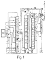
- the air separation plant shown in FIG. 1 has a double column rectifier Main condenser 1, pressure column 2 and low pressure column 3 for the recovery of Nitrogen at the top of the low pressure column 3 and oxygen from the bottom of the Low pressure column 3 on.
- the double column is in common with the Unterkühlungsurgiströmer 4 and other cold components, not shown, such as e.g. cryogenic pumps, housed in several cold boxes, their arrangement will be explained in more detail with reference to FIGS 2 to 6.
- the argon rectification unit consists of two partial columns 6, 7, which are the crude argon column form a pure argon column 8 and the corresponding top condensers 9, 10th
- the first part of the column 6 is in the usual way by a line 17 through which a in essential oxygen and argon-containing fraction in the first part of the column. 6 can be fed, connected to the low pressure column 3.
- the return 18 serves for the return of itself in the bottom of the first part of column 6 accumulating Residual liquid to the low pressure column 3.
- this return line 18 is a pump 12 for Promotion of the residual liquid provided.
- the first partial column 6 has no top condenser.
- the return fluid for this Column 6 is formed by the bottom liquid of the second partial column 7, which by means of a pump 11 is pumped to the head of the sub-column 6.
- In the head capacitor 9 is Return liquid for the second part 7 of the crude argon column by condensation of Overhead fraction in indirect heat exchange against bottom liquid from the pressure column 2, which is supplied via line 19, generated.
- the resulting steam is via line 13 returned to the low pressure column 3.
- excess Bottom liquid is from the top condenser 9 via line 14 in the Low pressure column 3 fed.
- the head capacitor 10 th the pure argon column 8 supplied with bottoms liquid from the pressure column 2. Waste incurred Steam and excess liquid are supplied via lines 15 and 16 which are in the Lines 13 and 14 open, also passed into the low pressure column 3.
- the second part of the column 7th containing coldbox 25 is designed as a main box, which is the first part of the column. 6 containing coldbox 24 is assigned as a secondary box.
- the main box 25 includes in addition to the partial column 7, the argon head condenser 9, the pure argon column 8 and their head capacitor 10. Femer are more than three quarters of the accessories of the first Partial column 6, i. the measuring and control equipment, the fittings and the Inspection facilities, as well as more than three quarters of the casing of the first Partial column arranged in the main box 25.
- FIG. 2b shows an alternative embodiment in which a common cold box 26 is provided for the pressure column 2 and the low pressure column 3.
- the cold boxes 24, 25 the two sub-columns 6 and 7 also have the explained with reference to Figure 2a Main box-auxiliary box ratio.
- the individual cold boxes are interconnected via junction boxes in which For example, the connecting lines extend, connected to each other. It is at all arrangements shown in the figures also advantageous, two or more Coldboxes that need to be connected, right next to each other to connect to each other and to the common wall of coldboxes remove so that a single coldbox is created.
- the two embodiments of Figure 3a and Figure 3b differ from those Figures 2a and 2b in that the second part of column 7 also in a Secondary box 27 is located.
- the main box 28 comprises the majority of the Accessories of the two partial columns 6, 7, the pure argon column 8 and the Capacitors 9, 10 and the pure argon column 8. Further, the cold, i. to be isolated Piping of the two Rohargonteilmodule 6, 7 included in the main box 28.
- the Pressure column 2 and the low pressure column 3 are each in a separate coldbox 22, 23 housed.
- Figure 3b corresponds substantially to Figure 3a, but with the pressure column 2 and the low pressure column 3, analogous to the embodiment of Figure 2b, in a common Coldbox 26 are located.
- the argon rectification unit with the two partial columns 6, 7 becomes on two secondary boxes 24, 27 for the partial columns 6, 7 and a main box 28, the corresponding accessories and the piping contains, split.
- FIGS. 4 to 6 show further embodiments of the invention Concept for the distribution of cold boxes in main and secondary boxes.
- FIG 4a a cryogenic air separation plant is shown in which the coldbox for the double column consisting of pressure column 2 and low pressure column 3 divided according to the invention.
- the low pressure column 3 in a Maubox 35 housed.
- the pressure column 2 with the main capacitor and the Accessories of the low-pressure column 3 is located in the main box 34th Die Rohargonklale is divided and, as already shown in Figure 2, also in two as Main and secondary box running coldboxes 24, 25 arranged. This execution allows the transport of the individual modules with the associated coldboxes.
- Figure 4b shows a modification of the arrangement of Figure 4a, in which the crude argon column divided and housed in two cold boxes 31, 32, in which the two cold boxes 31, 32 for the first and the second partial column 6, 7 in conventional Are executed, i. E. in which all of the respective sub-column 6, 7 associated accessories are also located in the corresponding Coldbox 31, 32.
- a common cold box 33 provided for the two partial columns 6, 7 for argon production.
- the two Partial columns 6, 7 are usually arranged side by side. It has, however also proved to be favorable, the second partial column 7 with the top condenser under the first partial column 6 provide. Since the sump of the first sub-column 6 at the level of Argon deduction from the low pressure column 3 is located in the cold box 33 below the first sub-column 6 space, which is preferably used for the second sub-column 7. To supply the first part of column 6 with return liquid bottoms liquid is made the second part of the column 7 pumped to the head of the first part of the column 6.
- FIGS. 5a to 5c correspond to the arrangements according to FIGS Figures 4a to 4c, wherein only the main box-Nebenbox-relationship between the Pressure column box and the low pressure column box is reversed.
- the main capacitor can either with the low pressure column 3 and the accessories of the pressure column. 2 and those of the low-pressure column 3 are arranged in the main box 30 or preferably placed on or above the pressure column 2 and in the secondary box 29th to be built in.
- FIGS. 6a to 6d show further advantageous variants.
- FIG 6a is a separate main box 36 for the accessories of the pressure column 2 and the Low pressure column 3 is provided.
- the pressure column 2 and the low pressure column 3 are In contrast, each housed in a secondary box 29, 35.
- the secondary box 29 with the pressure column also still the main capacitor integrated.
- the two partial columns 6, 7 of the crude argon column are also in two over the main box-secondary box principle according to the invention interconnected.
- FIGS. 6b and 6c show slight modifications of the arrangement according to FIG. 6a which the two partial columns 6, 7 on the one hand in two conventional, not housed according to the invention cold boxes 31, 32 (Figure 6b) housed are to be found on the other hand in a common coldbox 33 ( Figure 6c).
- Figure 6d an arrangement is shown in which both the pressure 2 and the low-pressure column 3 and the two sub-columns 6, 7 in separate sub-boxes 29, 35, 24, 27 are housed and two main boxes 36, 28 are provided, the on the one hand the secondary boxes 29, 35, on the other hand associated with the secondary boxes 24, 27 are.
- a single main box with the four secondary boxes 29, 35, 24, 27 is connected.
- the different figures are supposed to be the kind of for the different modules used cold boxes, i. whether a main box, a secondary box or a conventional cold box is used, clarify. Their arrangement to each other is not necessarily reproduced correctly in the figures.
- the Coldboxes arranged so that the coldboxes, between which many Pipe connections and other connecting lines run as close as possible stand together. So it is advantageous, for example, the cold box 21 with the Main heat exchanger next to the low pressure column box to arrange and the Pressure column box and the crude argon column box (s) to the low pressure column box to be bordered.
- the connection of the cold boxes with each other via isolated connection boxes or by joining the affected cold boxes and removing the partition.
Landscapes
- Engineering & Computer Science (AREA)
- Physics & Mathematics (AREA)
- Mechanical Engineering (AREA)
- Thermal Sciences (AREA)
- General Engineering & Computer Science (AREA)
- Separation By Low-Temperature Treatments (AREA)
- Sorption Type Refrigeration Machines (AREA)
- Air-Conditioning For Vehicles (AREA)
- Compression-Type Refrigeration Machines With Reversible Cycles (AREA)
Description
- Figur 1
- das Verfahrensschema einer erfindungsgemäßen Luftzerlegungsanlage,
- Figuren 2a und 2b
- erfindungsgemäße Luftzerlegungsanlagen, bei denen eine geteilte Rohargonsäule in einer Haupt- und einer Nebenbox untergebracht ist,
- Figuren 3a und 3b
- eine alternative Aufteilung einer geteilten Rohargonsäule auf Haupt- und Nebenboxen und die
- Figuren 4 bis 6
- analoge Ausführungen bei einer Aufteilung von Druck- und Niederdrucksäule auf Haupt- und Nebenboxen.
Claims (13)
- Tieftemperaturluftzerlegungsanlage mit mehreren Modulen, die mindestens eine Wärmetauschereinheit, eine Drucksäule und eine Niederdrucksäule umfassen, sowie mit den den jeweiligen Modulen zugehörigen Zubehörteilen und mit mindestens zwei Coldboxen, in denen die Module und / oder die Zubehörteile angeordnet sind, dadurch gekennzeichnet, dass mindestens eine der Coldboxen als Hauptbox (25, 28, 30, 34, 36) und mindestens eine der Coldboxen als Nebenbox (24, 27, 29, 35) ausgeführt ist, wobei die Nebenbox (24, 27, 29, 35) mindestens eines der Module (2, 3, 6, 7) beinhaltet und sich die Zubehörteile des in der Nebenbox (24, 27, 29, 35) angeordneten Moduls (2, 3, 6, 7) überwiegend in der Hauptbox (25, 28, 30, 34, 36) befinden.
- Tieftemperaturluftzerlegungsanlage nach Anspruch 1, dadurch gekennzeichnet, dass sich in der Hauptbox (25, 30, 34) mindestens ein Modul (2, 3, 7) befindet.
- Tieftemperaturluftzerlegungsanlage nach Anspruch 1, dadurch gekennzeichnet, dass sich in der Hauptbox (28, 36) kein Modul befindet.
- Tieftemperaturluftzerlegungsanlage nach einem der Ansprüche 1 bis 3, dadurch gekennzeichnet, dass eine Rohargonrektifikationseinheit vorgesehen ist, die eine erste und eine zweite Teilsäule (6, 7), eine Rohargonleitung, die vom oberen Bereich der ersten Teilsäule (6) in den unteren Bereich der zweiten Teilsäule (7) führt, Mittel (11) zum Zurückführen von Rücklaufflüssigkeit vom Sumpf der zweiten Teilsäule (7) in den oberen Bereich der ersten Teilsäule (6) sowie einen Argonkopfkondensator (9), dessen Kondensationsseite mit dem oberen Bereich der zweiten Teilsäule (7) verbunden ist, umfasst, wobei die Nebenbox (24) die erste Teilsäule (6) und die Hauptbox (25) die zweite Teilsäule (7) sowie den Argonkopfkondensator (9) und den überwiegenden Teil der Zubehörteile der ersten Teilsäule (6) beinhaltet.
- Tieftemperaturluftzerlegungsanlage nach Anspruch 4, dadurch gekennzeichnet, dass die Hauptbox (25) eine Reinargonsäule (8) beinhaltet.
- Tieftemperaturluftzerlegungsanlage nach einem der Ansprüche 1 bis 3, dadurch gekennzeichnet, dass eine Rohargonrektifikationseinheit vorgesehen ist, die eine erste und eine zweite Teilsäule (6, 7), eine Rohargonleitung, die vom oberen Bereich der ersten Teilsäule (6) in den unteren Bereich der zweiten Teilsäule (7) führt, Mittel (11) zum Zurückführen von Rücklaufflüssigkeit vom Sumpf der zweiten Teilsäule (7) in den oberen Bereich der ersten Teilsäule (6) sowie einen Argonkopfkondensator (9), dessen Kondensationsseite mit dem oberen Bereich der zweiten Teilsäule (7) verbunden ist, umfasst, wobei die Hauptbox (28) den überwiegenden Teil der Zubehörteile der Rohargonrektifikationseinheit beinhaltet und die erste Teilsäule (6) in einer ersten Nebenbox (24) und die zweite Teilsäule (7) und der Argonkopfkondensator (9) in einer zweiten Nebenbox (27) untergebracht sind.
- Tieftemperaturluftzerlegungsanlage nach Anspruch 6, dadurch gekennzeichnet, dass die zweite Nebenbox (27) eine Reinargonsäule (8) beinhaltet.
- Tieftemperaturluftzerlegungsanlage nach einem der Ansprüche 1 bis 7, dadurch gekennzeichnet, dass sich mehr als 60%, bevorzugt mehr als 70%, besonders bevorzugt mehr als 80 % der Zubehörteile in der Hauptbox (25, 28, 30, 34, 36) befinden.
- Tieftemperaturluftzerlegungsanlage nach einem der Ansprüche 1 bis 8, dadurch gekennzeichnet, dass sich die Drucksäule (2) und die Niederdrucksäule (3) in je einer Nebenbox (29, 35) befinden und die Hauptbox (36) im wesentlichen nur die Zubehörteile der Drucksäule (2) und der Niederdrucksäule (3) beinhaltet.
- Tieftemperaturluftzerlegungsanlage nach einem der Ansprüche 1 bis 8, dadurch gekennzeichnet, dass sich in der Hauptbox (30) die Niederdrucksäule (3) und in der Nebenbox (29) die Drucksäule (2) befindet.
- Tieftemperaturluftzerlegungsanlage nach einem der Ansprüche 1 bis 8, dadurch gekennzeichnet, dass sich in der Hauptbox (34) die Drucksäule (2) und in der Nebenbox (35) die Niederdrucksäule (3) befindet.
- Tieftemperaturluftzerlegungsanlage nach einem der Ansprüche 1 bis 11, dadurch gekennzeichnet, dass eine Nebenbox vorgesehen ist, die eine Rohargonrektifikationseinheit beinhaltet.
- Tieftemperaturluftzerlegungsanlage nach einem der Ansprüche 1 bis 12, dadurch gekennzeichnet, dass sich die dem in der Nebenbox (24, 29, 35) angeordneten Modul (2, 3, 6, 7) zugeordnete Verrohrung überwiegend in der Hauptbox (25, 28, 30, 34, 36) befindet.
Priority Applications (1)
| Application Number | Priority Date | Filing Date | Title |
|---|---|---|---|
| EP01974179A EP1309827B1 (de) | 2000-08-18 | 2001-08-13 | Tieftemperaturluftzerlegungsanlage |
Applications Claiming Priority (6)
| Application Number | Priority Date | Filing Date | Title |
|---|---|---|---|
| DE10040391A DE10040391A1 (de) | 2000-08-18 | 2000-08-18 | Tieftemperaturluftzerlegungsanlage |
| DE10040391 | 2000-08-18 | ||
| EP00122779A EP1180655A1 (de) | 2000-08-18 | 2000-10-19 | Tieftemperaturluftzerlegungsanlage |
| EP00122779 | 2000-10-19 | ||
| PCT/EP2001/009348 WO2002016847A1 (de) | 2000-08-18 | 2001-08-13 | Tieftemperaturluftzerlegungsanlage |
| EP01974179A EP1309827B1 (de) | 2000-08-18 | 2001-08-13 | Tieftemperaturluftzerlegungsanlage |
Publications (2)
| Publication Number | Publication Date |
|---|---|
| EP1309827A1 EP1309827A1 (de) | 2003-05-14 |
| EP1309827B1 true EP1309827B1 (de) | 2005-05-11 |
Family
ID=7652867
Family Applications (2)
| Application Number | Title | Priority Date | Filing Date |
|---|---|---|---|
| EP00122779A Withdrawn EP1180655A1 (de) | 2000-08-18 | 2000-10-19 | Tieftemperaturluftzerlegungsanlage |
| EP01974179A Expired - Lifetime EP1309827B1 (de) | 2000-08-18 | 2001-08-13 | Tieftemperaturluftzerlegungsanlage |
Family Applications Before (1)
| Application Number | Title | Priority Date | Filing Date |
|---|---|---|---|
| EP00122779A Withdrawn EP1180655A1 (de) | 2000-08-18 | 2000-10-19 | Tieftemperaturluftzerlegungsanlage |
Country Status (10)
| Country | Link |
|---|---|
| US (1) | US6948337B2 (de) |
| EP (2) | EP1180655A1 (de) |
| JP (1) | JP2004535543A (de) |
| KR (1) | KR100752818B1 (de) |
| CN (1) | CN1239874C (de) |
| AT (1) | ATE295520T1 (de) |
| AU (1) | AU2001293766A1 (de) |
| DE (2) | DE10040391A1 (de) |
| TW (1) | TW500908B (de) |
| WO (1) | WO2002016847A1 (de) |
Families Citing this family (14)
| Publication number | Priority date | Publication date | Assignee | Title |
|---|---|---|---|---|
| GB0307404D0 (en) * | 2003-03-31 | 2003-05-07 | Air Prod & Chem | Apparatus for cryogenic air distillation |
| US7284395B2 (en) * | 2004-09-02 | 2007-10-23 | Praxair Technology, Inc. | Cryogenic air separation plant with reduced liquid drain loss |
| US7621152B2 (en) * | 2006-02-24 | 2009-11-24 | Praxair Technology, Inc. | Compact cryogenic plant |
| FR2946735B1 (fr) * | 2009-06-12 | 2012-07-13 | Air Liquide | Appareil et procede de separation d'air par distillation cryogenique. |
| DE102010012920A1 (de) * | 2010-03-26 | 2011-09-29 | Linde Aktiengesellschaft | Vorrichtung zur Tieftemperaturzerlegung von Luft |
| DE102012008415A1 (de) * | 2012-04-27 | 2013-10-31 | Linde Aktiengesellschaft | Transportables Paket mit einer Coldbox, Tieftemperatur-Luftzerlegungsanlage und Verfahren zum Herstellen einer Tieftemperatur-Luftzerlegungsanlage |
| US10591209B2 (en) * | 2013-03-06 | 2020-03-17 | Linde Aktiengesellschaft | Air separation plant, method for obtaining a product containing argon, and method for creating an air separation plant |
| CN104019631B (zh) * | 2014-06-26 | 2016-03-16 | 莱芜钢铁集团有限公司 | 一种空气分离装置快速投氩方法 |
| CN104501530B (zh) * | 2014-12-25 | 2017-05-17 | 杭州杭氧股份有限公司 | 一种利用多套空分制取的粗氩提取高纯液氩的装置及方法 |
| WO2019144380A1 (en) | 2018-01-26 | 2019-08-01 | L'air Liquide, Societe Anonyme Pour L'etude Et L'exploitation Des Procedes Georges Claude | Air separation unit by cryogenic distillation |
| EP3614082A1 (de) * | 2018-08-22 | 2020-02-26 | Linde Aktiengesellschaft | Luftzerlegungsanlage, verfahren zur tieftemperaturzerlegung von luft und verfahren zur erstellung einer luftzerlegungsanlage |
| EP3614083A1 (de) * | 2018-08-22 | 2020-02-26 | Linde Aktiengesellschaft | Luftzerlegungsanlage, verfahren zur tieftemperaturzerlegung von luft mittels luftzerlegungsanlage und verfahren zur erstellung einer luftzerlegungsanlage |
| CN109676367A (zh) * | 2018-12-28 | 2019-04-26 | 乔治洛德方法研究和开发液化空气有限公司 | 一种热交换器组件及装配所述热交换器组件的方法 |
| FR3116892B1 (fr) * | 2020-12-02 | 2022-12-30 | Air Liquide | Appareil de séparation d’air par distillation cryogénique |
Family Cites Families (18)
| Publication number | Priority date | Publication date | Assignee | Title |
|---|---|---|---|---|
| DE2822774C2 (de) * | 1978-05-24 | 1982-08-26 | Linde Ag, 6200 Wiesbaden | Verfahren und Anlagenteile zum Errichten einer Fabrikanlage |
| JPS6176296U (de) * | 1984-10-24 | 1986-05-22 | ||
| FR2649962B1 (fr) * | 1989-06-06 | 1993-04-02 | Christian Huon | Unites usines modulaires containerisees pour la fabrication, la transformation et/ou l'elaboration de produits agro-alimentaires |
| JPH0338656A (ja) * | 1989-07-05 | 1991-02-19 | Ricoh Co Ltd | 複写機の操作パネル制御装置 |
| FR2692663B1 (fr) * | 1992-06-17 | 1994-08-19 | Air Liquide | Procédé de construction d'une unité cryogénique de séparation de gaz, unité cryogénique, sous-ensemble et ensemble transportable pour la construction d'une telle unité. |
| FR2695714B1 (fr) * | 1992-09-16 | 1994-10-28 | Maurice Grenier | Installation de traitement cryogénique, notamment de distillation d'air. |
| FR2706025B1 (fr) * | 1993-06-03 | 1995-07-28 | Air Liquide | Installation de distillation d'air. |
| US5522224A (en) * | 1994-08-15 | 1996-06-04 | Praxair Technology, Inc. | Model predictive control method for an air-separation system |
| JP3526648B2 (ja) * | 1995-03-23 | 2004-05-17 | エア・ウォーター株式会社 | 高純度窒素ガス製造装置 |
| FR2752530B1 (fr) * | 1996-08-21 | 1998-09-25 | Air Liquide | Installation de separation d'un melange gazeux |
| GB9623519D0 (en) * | 1996-11-11 | 1997-01-08 | Boc Group Plc | Air separation |
| US6205815B1 (en) * | 1997-04-11 | 2001-03-27 | L'air Liquide, Societe Anonyme Pour L'etude Et L'exploitation Des Procedes Georges Claude | Plant for separation of a gas mixture by distillation |
| JPH10325674A (ja) * | 1997-05-28 | 1998-12-08 | Nippon Air Rikiide Kk | 空気液化分離装置 |
| FR2769656B1 (fr) * | 1997-10-14 | 1999-12-17 | Air Liquide | Procede de realisation d'un paquet par assemblage d'une structure interieure de confinement de fluide, d'une structure exterieure et d'equipements, et procede de construction sur site utilisant un tel paquet |
| FR2774752B1 (fr) * | 1998-02-06 | 2000-06-16 | Air Liquide | Installation de distillation d'air et boite froide correspondante |
| FR2778234B1 (fr) * | 1998-04-30 | 2000-06-02 | Air Liquide | Installation de distillation d'air et boite froide correspondante |
| FR2780147B1 (fr) * | 1999-06-29 | 2001-01-05 | Air Liquide | Installation de distillation d'air et boite froide correspondante |
| US6212907B1 (en) * | 2000-02-23 | 2001-04-10 | Praxair Technology, Inc. | Method for operating a cryogenic rectification column |
-
2000
- 2000-08-18 DE DE10040391A patent/DE10040391A1/de not_active Withdrawn
- 2000-10-19 EP EP00122779A patent/EP1180655A1/de not_active Withdrawn
-
2001
- 2001-08-13 AU AU2001293766A patent/AU2001293766A1/en not_active Abandoned
- 2001-08-13 US US10/344,667 patent/US6948337B2/en not_active Expired - Fee Related
- 2001-08-13 JP JP2002521901A patent/JP2004535543A/ja active Pending
- 2001-08-13 CN CNB018143288A patent/CN1239874C/zh not_active Expired - Fee Related
- 2001-08-13 EP EP01974179A patent/EP1309827B1/de not_active Expired - Lifetime
- 2001-08-13 AT AT01974179T patent/ATE295520T1/de not_active IP Right Cessation
- 2001-08-13 KR KR1020037002302A patent/KR100752818B1/ko not_active Expired - Fee Related
- 2001-08-13 DE DE50106217T patent/DE50106217D1/de not_active Expired - Lifetime
- 2001-08-13 WO PCT/EP2001/009348 patent/WO2002016847A1/de not_active Ceased
- 2001-08-17 TW TW090120252A patent/TW500908B/zh not_active IP Right Cessation
Also Published As
| Publication number | Publication date |
|---|---|
| JP2004535543A (ja) | 2004-11-25 |
| DE50106217D1 (de) | 2005-06-16 |
| CN1447895A (zh) | 2003-10-08 |
| US6948337B2 (en) | 2005-09-27 |
| KR100752818B1 (ko) | 2007-08-29 |
| ATE295520T1 (de) | 2005-05-15 |
| KR20040002838A (ko) | 2004-01-07 |
| DE10040391A1 (de) | 2002-02-28 |
| AU2001293766A1 (en) | 2002-03-04 |
| TW500908B (en) | 2002-09-01 |
| US20040000166A1 (en) | 2004-01-01 |
| EP1180655A1 (de) | 2002-02-20 |
| WO2002016847A1 (de) | 2002-02-28 |
| CN1239874C (zh) | 2006-02-01 |
| EP1309827A1 (de) | 2003-05-14 |
Similar Documents
| Publication | Publication Date | Title |
|---|---|---|
| DE19904527B4 (de) | Luftdestillationsanlage mit mehreren kryogenen Destillationseinheiten des gleichen Typs | |
| EP1243882B1 (de) | Argongewinnung mit einem Drei-Säulen-System zur Luftzerlegung und einer Rohargonsäule | |
| DE19904526B4 (de) | Luftdestillationsanlage und zugehörige Kältebox | |
| EP0669509B1 (de) | Verfahren und Vorrichtung zur Gewinnung von reinem Argon | |
| EP1180655A1 (de) | Tieftemperaturluftzerlegungsanlage | |
| DE19803437A1 (de) | Verfahren und Vorrichtung zur Gewinnung eines Druckprodukts durch Tieftemperaturzerlegung von Luft | |
| EP2841858A2 (de) | Transportables paket mit einer coldbox,tieftemperatur-luftzerlegungsanlage und verfahren zum herstellen einer tieftemperatur-luftzerlegungsanlage | |
| EP2986924B1 (de) | Nachrüstbare vorrichtung zur tieftemperaturzerlegung von luft, nachrüstanlage und verfahren zum nachrüsten einer tieftemperatur-luftzerlegungsanlage | |
| WO2020038608A1 (de) | Luftzerlegungsanlage, verfahren zur tieftemperaturzerlegung von luft und verfahren zur erstellung einer luftzerlegungsanlage | |
| DE10161584A1 (de) | Vorrichtung und Verfahren zur Erzeugung gasförmigen Sauerstoffs unter erhöhtem Druck | |
| DE10302389A1 (de) | Verfahren und Vorrichtung zur Tieftemperaturzerlegung von Luft | |
| WO2016146246A1 (de) | Anlage zur erzeugung von sauerstoff durch tieftemperaturzerlegung von luft | |
| DE69909161T2 (de) | Tieftemperaturrektifikationsvorrichtung mit seriellen Säulen zur hochreinen Stickstoffherstellung | |
| DE19957017A1 (de) | Vorrichtung zur Gewinnung von Argon | |
| DE19919587A1 (de) | Luftdestillationsanlage und Kältebox | |
| EP3067650A1 (de) | Anlage und verfahren zur erzeugung von sauerstoff durch tieftemperaturzerlegung von luft | |
| WO2020038607A2 (de) | Verfahren und anlage zur tieftemperaturzerlegung von luft | |
| DE10000017A1 (de) | Verfahren zur Gewinnung von Krypton und/oder Xenon durch Tieftemperaturzerlegung von Luft | |
| EP2645032A1 (de) | Transportables Paket mit einer Coldbox und Verfahren zum Herstellen einer Tieftemperatur-Luftzerlegungsanlage | |
| DE10045128A1 (de) | Verfahren und Vorrichtung zur Erzeugung hoch reinen Stickstoffs durch Tieftemperatur-Luftzerlegung | |
| EP4396508A2 (de) | Anlage und verfahren zur tieftemperaturzerlegung von luft | |
| DE10332862A1 (de) | Verfahren und Vorrichtung zur Gewinnung von Krypton und/oder Xenon durch Tieftemperaturzerlegung | |
| EP1052465A1 (de) | Verfahren und Vorrichung zur Tieftemperaturzerlegung von Luft | |
| WO2020038606A1 (de) | Luftzerlegungsanlage, verfahren zur tieftemperaturzerlegung von luft mittels luftzerlegungsanlage und verfahren zur erstellung einer luftzerlegungsanlage | |
| DE102019001960A1 (de) | Verfahren und Anlage zur Tieftemperaturzerlegung von Luft |
Legal Events
| Date | Code | Title | Description |
|---|---|---|---|
| PUAI | Public reference made under article 153(3) epc to a published international application that has entered the european phase |
Free format text: ORIGINAL CODE: 0009012 |
|
| 17P | Request for examination filed |
Effective date: 20030110 |
|
| AK | Designated contracting states |
Designated state(s): AT BE CH CY DE DK ES FI FR GB GR IE IT LI LU MC NL PT SE TR |
|
| AX | Request for extension of the european patent |
Extension state: AL LT LV MK RO SI |
|
| GRAP | Despatch of communication of intention to grant a patent |
Free format text: ORIGINAL CODE: EPIDOSNIGR1 |
|
| GRAS | Grant fee paid |
Free format text: ORIGINAL CODE: EPIDOSNIGR3 |
|
| GRAA | (expected) grant |
Free format text: ORIGINAL CODE: 0009210 |
|
| AK | Designated contracting states |
Kind code of ref document: B1 Designated state(s): AT BE CH CY DE DK ES FI FR GB GR IE IT LI LU MC NL PT SE TR |
|
| PG25 | Lapsed in a contracting state [announced via postgrant information from national office to epo] |
Ref country code: ES Free format text: LAPSE BECAUSE OF FAILURE TO SUBMIT A TRANSLATION OF THE DESCRIPTION OR TO PAY THE FEE WITHIN THE PRESCRIBED TIME-LIMIT Effective date: 20050511 Ref country code: IE Free format text: LAPSE BECAUSE OF FAILURE TO SUBMIT A TRANSLATION OF THE DESCRIPTION OR TO PAY THE FEE WITHIN THE PRESCRIBED TIME-LIMIT Effective date: 20050511 Ref country code: TR Free format text: LAPSE BECAUSE OF FAILURE TO SUBMIT A TRANSLATION OF THE DESCRIPTION OR TO PAY THE FEE WITHIN THE PRESCRIBED TIME-LIMIT Effective date: 20050511 |
|
| REG | Reference to a national code |
Ref country code: GB Ref legal event code: FG4D Free format text: NOT ENGLISH |
|
| REG | Reference to a national code |
Ref country code: CH Ref legal event code: EP |
|
| REG | Reference to a national code |
Ref country code: IE Ref legal event code: FG4D Free format text: LANGUAGE OF EP DOCUMENT: GERMAN |
|
| REF | Corresponds to: |
Ref document number: 50106217 Country of ref document: DE Date of ref document: 20050616 Kind code of ref document: P |
|
| PG25 | Lapsed in a contracting state [announced via postgrant information from national office to epo] |
Ref country code: GR Free format text: LAPSE BECAUSE OF FAILURE TO SUBMIT A TRANSLATION OF THE DESCRIPTION OR TO PAY THE FEE WITHIN THE PRESCRIBED TIME-LIMIT Effective date: 20050811 Ref country code: DK Free format text: LAPSE BECAUSE OF FAILURE TO SUBMIT A TRANSLATION OF THE DESCRIPTION OR TO PAY THE FEE WITHIN THE PRESCRIBED TIME-LIMIT Effective date: 20050811 |
|
| PG25 | Lapsed in a contracting state [announced via postgrant information from national office to epo] |
Ref country code: CY Free format text: LAPSE BECAUSE OF FAILURE TO SUBMIT A TRANSLATION OF THE DESCRIPTION OR TO PAY THE FEE WITHIN THE PRESCRIBED TIME-LIMIT Effective date: 20050813 Ref country code: LU Free format text: LAPSE BECAUSE OF NON-PAYMENT OF DUE FEES Effective date: 20050813 |
|
| REG | Reference to a national code |
Ref country code: SE Ref legal event code: TRGR |
|
| PG25 | Lapsed in a contracting state [announced via postgrant information from national office to epo] |
Ref country code: MC Free format text: LAPSE BECAUSE OF NON-PAYMENT OF DUE FEES Effective date: 20050831 Ref country code: LI Free format text: LAPSE BECAUSE OF NON-PAYMENT OF DUE FEES Effective date: 20050831 Ref country code: CH Free format text: LAPSE BECAUSE OF NON-PAYMENT OF DUE FEES Effective date: 20050831 Ref country code: BE Free format text: LAPSE BECAUSE OF NON-PAYMENT OF DUE FEES Effective date: 20050831 |
|
| GBT | Gb: translation of ep patent filed (gb section 77(6)(a)/1977) |
Effective date: 20050909 |
|
| PG25 | Lapsed in a contracting state [announced via postgrant information from national office to epo] |
Ref country code: PT Free format text: LAPSE BECAUSE OF FAILURE TO SUBMIT A TRANSLATION OF THE DESCRIPTION OR TO PAY THE FEE WITHIN THE PRESCRIBED TIME-LIMIT Effective date: 20051019 |
|
| REG | Reference to a national code |
Ref country code: IE Ref legal event code: FD4D |
|
| PLBE | No opposition filed within time limit |
Free format text: ORIGINAL CODE: 0009261 |
|
| STAA | Information on the status of an ep patent application or granted ep patent |
Free format text: STATUS: NO OPPOSITION FILED WITHIN TIME LIMIT |
|
| ET | Fr: translation filed | ||
| REG | Reference to a national code |
Ref country code: CH Ref legal event code: PL |
|
| 26N | No opposition filed |
Effective date: 20060214 |
|
| BERE | Be: lapsed |
Owner name: LINDE A.G. Effective date: 20050831 |
|
| REG | Reference to a national code |
Ref country code: FR Ref legal event code: CA |
|
| PGFP | Annual fee paid to national office [announced via postgrant information from national office to epo] |
Ref country code: FR Payment date: 20090814 Year of fee payment: 9 |
|
| PGFP | Annual fee paid to national office [announced via postgrant information from national office to epo] |
Ref country code: AT Payment date: 20090812 Year of fee payment: 9 Ref country code: DE Payment date: 20090806 Year of fee payment: 9 Ref country code: FI Payment date: 20090813 Year of fee payment: 9 Ref country code: GB Payment date: 20090812 Year of fee payment: 9 Ref country code: NL Payment date: 20090803 Year of fee payment: 9 Ref country code: SE Payment date: 20090806 Year of fee payment: 9 |
|
| PGFP | Annual fee paid to national office [announced via postgrant information from national office to epo] |
Ref country code: IT Payment date: 20090814 Year of fee payment: 9 |
|
| REG | Reference to a national code |
Ref country code: NL Ref legal event code: V1 Effective date: 20110301 |
|
| EUG | Se: european patent has lapsed | ||
| GBPC | Gb: european patent ceased through non-payment of renewal fee |
Effective date: 20100813 |
|
| REG | Reference to a national code |
Ref country code: FR Ref legal event code: ST Effective date: 20110502 |
|
| PG25 | Lapsed in a contracting state [announced via postgrant information from national office to epo] |
Ref country code: FI Free format text: LAPSE BECAUSE OF NON-PAYMENT OF DUE FEES Effective date: 20100813 Ref country code: NL Free format text: LAPSE BECAUSE OF NON-PAYMENT OF DUE FEES Effective date: 20110301 Ref country code: IT Free format text: LAPSE BECAUSE OF NON-PAYMENT OF DUE FEES Effective date: 20100813 Ref country code: AT Free format text: LAPSE BECAUSE OF NON-PAYMENT OF DUE FEES Effective date: 20100813 |
|
| REG | Reference to a national code |
Ref country code: DE Ref legal event code: R119 Ref document number: 50106217 Country of ref document: DE Effective date: 20110301 |
|
| PG25 | Lapsed in a contracting state [announced via postgrant information from national office to epo] |
Ref country code: DE Free format text: LAPSE BECAUSE OF NON-PAYMENT OF DUE FEES Effective date: 20110301 Ref country code: FR Free format text: LAPSE BECAUSE OF NON-PAYMENT OF DUE FEES Effective date: 20100831 |
|
| PG25 | Lapsed in a contracting state [announced via postgrant information from national office to epo] |
Ref country code: GB Free format text: LAPSE BECAUSE OF NON-PAYMENT OF DUE FEES Effective date: 20100813 |
|
| PG25 | Lapsed in a contracting state [announced via postgrant information from national office to epo] |
Ref country code: SE Free format text: LAPSE BECAUSE OF NON-PAYMENT OF DUE FEES Effective date: 20100814 |