EP1309472B1 - Steuersystem für intelligente zünder - Google Patents
Steuersystem für intelligente zünder Download PDFInfo
- Publication number
- EP1309472B1 EP1309472B1 EP01901940A EP01901940A EP1309472B1 EP 1309472 B1 EP1309472 B1 EP 1309472B1 EP 01901940 A EP01901940 A EP 01901940A EP 01901940 A EP01901940 A EP 01901940A EP 1309472 B1 EP1309472 B1 EP 1309472B1
- Authority
- EP
- European Patent Office
- Prior art keywords
- smart
- ignitor
- memory device
- data
- control system
- Prior art date
- Legal status (The legal status is an assumption and is not a legal conclusion. Google has not performed a legal analysis and makes no representation as to the accuracy of the status listed.)
- Expired - Lifetime
Links
- 230000006854 communication Effects 0.000 claims description 24
- 238000004891 communication Methods 0.000 claims description 24
- 230000006870 function Effects 0.000 claims description 21
- 230000015654 memory Effects 0.000 claims description 7
- 230000003068 static effect Effects 0.000 claims description 4
- 230000007175 bidirectional communication Effects 0.000 claims 1
- 239000000463 material Substances 0.000 description 11
- 229910052751 metal Inorganic materials 0.000 description 8
- 239000002184 metal Substances 0.000 description 8
- 238000005065 mining Methods 0.000 description 8
- 235000015429 Mirabilis expansa Nutrition 0.000 description 7
- 244000294411 Mirabilis expansa Species 0.000 description 7
- 235000013536 miso Nutrition 0.000 description 7
- 239000004593 Epoxy Substances 0.000 description 6
- 238000000034 method Methods 0.000 description 6
- 230000004913 activation Effects 0.000 description 5
- 238000010586 diagram Methods 0.000 description 5
- 239000002360 explosive Substances 0.000 description 5
- 238000004519 manufacturing process Methods 0.000 description 5
- 239000004065 semiconductor Substances 0.000 description 5
- 238000012360 testing method Methods 0.000 description 5
- 238000010438 heat treatment Methods 0.000 description 4
- 238000012827 research and development Methods 0.000 description 4
- 238000010276 construction Methods 0.000 description 3
- 238000013528 artificial neural network Methods 0.000 description 2
- 238000010304 firing Methods 0.000 description 2
- 239000011521 glass Substances 0.000 description 2
- 238000012544 monitoring process Methods 0.000 description 2
- 230000008569 process Effects 0.000 description 2
- 230000004044 response Effects 0.000 description 2
- 238000012546 transfer Methods 0.000 description 2
- 230000003213 activating effect Effects 0.000 description 1
- 230000004075 alteration Effects 0.000 description 1
- 229910052782 aluminium Inorganic materials 0.000 description 1
- XAGFODPZIPBFFR-UHFFFAOYSA-N aluminium Chemical compound [Al] XAGFODPZIPBFFR-UHFFFAOYSA-N 0.000 description 1
- 230000005540 biological transmission Effects 0.000 description 1
- 238000004590 computer program Methods 0.000 description 1
- 230000007797 corrosion Effects 0.000 description 1
- 238000005260 corrosion Methods 0.000 description 1
- 238000005474 detonation Methods 0.000 description 1
- 230000009977 dual effect Effects 0.000 description 1
- 230000005611 electricity Effects 0.000 description 1
- 239000003623 enhancer Substances 0.000 description 1
- 238000004880 explosion Methods 0.000 description 1
- 230000000977 initiatory effect Effects 0.000 description 1
- 238000009434 installation Methods 0.000 description 1
- 238000002844 melting Methods 0.000 description 1
- 230000008018 melting Effects 0.000 description 1
- 229910001092 metal group alloy Inorganic materials 0.000 description 1
- 239000000615 nonconductor Substances 0.000 description 1
- 238000012545 processing Methods 0.000 description 1
- 239000003380 propellant Substances 0.000 description 1
- 239000000565 sealant Substances 0.000 description 1
- 229910052710 silicon Inorganic materials 0.000 description 1
- 239000010703 silicon Substances 0.000 description 1
- 239000000758 substrate Substances 0.000 description 1
- 230000001629 suppression Effects 0.000 description 1
- WFKWXMTUELFFGS-UHFFFAOYSA-N tungsten Chemical compound [W] WFKWXMTUELFFGS-UHFFFAOYSA-N 0.000 description 1
- 229910052721 tungsten Inorganic materials 0.000 description 1
- 239000010937 tungsten Substances 0.000 description 1
- 230000000007 visual effect Effects 0.000 description 1
- 238000010618 wire wrap Methods 0.000 description 1
Images





Classifications
-
- B—PERFORMING OPERATIONS; TRANSPORTING
- B60—VEHICLES IN GENERAL
- B60R—VEHICLES, VEHICLE FITTINGS, OR VEHICLE PARTS, NOT OTHERWISE PROVIDED FOR
- B60R21/00—Arrangements or fittings on vehicles for protecting or preventing injuries to occupants or pedestrians in case of accidents or other traffic risks
- B60R21/01—Electrical circuits for triggering passive safety arrangements, e.g. airbags, safety belt tighteners, in case of vehicle accidents or impending vehicle accidents
- B60R21/017—Electrical circuits for triggering passive safety arrangements, e.g. airbags, safety belt tighteners, in case of vehicle accidents or impending vehicle accidents including arrangements for providing electric power to safety arrangements or their actuating means, e.g. to pyrotechnic fuses or electro-mechanic valves
-
- B—PERFORMING OPERATIONS; TRANSPORTING
- B60—VEHICLES IN GENERAL
- B60R—VEHICLES, VEHICLE FITTINGS, OR VEHICLE PARTS, NOT OTHERWISE PROVIDED FOR
- B60R21/00—Arrangements or fittings on vehicles for protecting or preventing injuries to occupants or pedestrians in case of accidents or other traffic risks
- B60R21/01—Electrical circuits for triggering passive safety arrangements, e.g. airbags, safety belt tighteners, in case of vehicle accidents or impending vehicle accidents
- B60R21/017—Electrical circuits for triggering passive safety arrangements, e.g. airbags, safety belt tighteners, in case of vehicle accidents or impending vehicle accidents including arrangements for providing electric power to safety arrangements or their actuating means, e.g. to pyrotechnic fuses or electro-mechanic valves
- B60R21/0173—Diagnostic or recording means therefor
-
- B—PERFORMING OPERATIONS; TRANSPORTING
- B60—VEHICLES IN GENERAL
- B60R—VEHICLES, VEHICLE FITTINGS, OR VEHICLE PARTS, NOT OTHERWISE PROVIDED FOR
- B60R21/00—Arrangements or fittings on vehicles for protecting or preventing injuries to occupants or pedestrians in case of accidents or other traffic risks
- B60R21/02—Occupant safety arrangements or fittings, e.g. crash pads
- B60R21/16—Inflatable occupant restraints or confinements designed to inflate upon impact or impending impact, e.g. air bags
- B60R21/26—Inflatable occupant restraints or confinements designed to inflate upon impact or impending impact, e.g. air bags characterised by the inflation fluid source or means to control inflation fluid flow
- B60R2021/26029—Ignitors
Definitions
- the present invention relates to an apparatus for control, communication, status acquisition, archival, and linking of a smart ignitor control system.
- Smart ignitors are pyrotechnic ignitors that can be electrically connected in parallel each with a unique address that allows each smart ignitor to be individually controlled, communicated with or have its status interrogated.
- vehicle safety devices including but not limited to variably deployable frontal airbags, side airbags, inflatable side curtains, and seat belt pretensioner safety systems than could be done otherwise.
- Smart ignitors may be used in the activation of gas generating devices, opening containers of stored gas, and hybrid type inflators. It would also be advantageous to have similar capabilities for selectively igniting various units of reactive materials, such as explosives, in mining or demolition operations.
- the smart ignitor control system disclosed herein can validate the functionality, control the timing and sequence of the deployment of the smart ignitors of a vehicle safety system in the event of a crash, or when explosives are used in mining or demolition operations.
- US5957988 teaches a control circuit for controlling power supplied to an ignitor element but the control circuit is hardware in a permanent configuration rather than being software that can be easily adapted to particular applications as in the present invention.
- US5957988 discloses a control circuit for controlling power supplied to an ignitor element, including first input for receiving an encoded input signal generated in response to the initiation of a firing mode and a diagnostic mode.
- the encoded input signal comprises a code portion having at least two pulses, and a power portion.
- Logic circuitry determines whether the code portion is valid, the code portion being determined valid when it meets pre-defined conditions within a predetermined time window, and provides an unlocking signal (Sfire) at an output when the code portion is determined to be valid.
- a switch which has a control input coupled to the output of the logic circuitry, is enabled on receipt of the unlocking signal so that power at the first input of the control circuit is supplied to the output of the switch for energizing the ignitor element.
- the power supplied via the enabled switch is sufficient to fire the ignitor element.
- the diagnostic mode the power portion supplied via the enabled switch energizes but does not fire the ignitor element such that diagnostics can be performed.
- US4843964 teaches a smart explosive ignitor and a device for sending an activation signal to the ignitor.
- US5554890, US5659474, US6068287 and WO97/28992 teach systems for controlling the activation of ignitors and/or diagnosing systems for controlling the activation of ignitors, but do not disclose the use of smart ignitors in such systems.
- a smart ignitor control system for controlling smart ignitors comprising:
- ignitor and “smart ignitors” are understood to mean pyrotechnic ignitors that can be electrically connected in parallel each with a unique address which allows each smart ignitor to be individually controlled, communicated with or have its status interrogated. It is understood in.the art that the term “squib” is synonymous with “ignitor”.
- Fig. 11 is a cross section of a smart ignitor 300 taught in commonly owned US 6 166 452. It is understood that the smart ignitor control system of the present invention may be employed with any suitable smart ignitor as defined above, and that the smart ignitor shown in Fig. 11 and described herein is merely exemplary.
- the exemplary smart ignitor 300 has a plastic end cap 303 provided on one end thereof.
- a metallic pin 304 passes through the end cap.
- the ignitor could contain two pins, one pin acting as a power supply pin and the other acting as a return pin, which would create an interface that is polarity independent.
- the pins perform the functions of conducting power to the ignitor and conducting digital communication signals between a slave ASIC in the ignitor and a master ASIC (102 in Figs. 1 and 2).
- the slave ASIC in each ignitor performs important function including, but not limited to, communicating with the master ASIC, diagnosing the functionality of the ignitor, maintaining a unique digital address for the particular ignitor (this address may be assigned either before or after installation of the ignitor in a particular safety device or location in a mining, demolition or construction scheme), controlling a charge pump, and activating a heating element such as a semiconductor bridge or hot wire.
- a three-pin configuration with two pins for the power supply and a third pin for conducting digital transmission signals could be employed.
- a metal disk 305 is provided directly below the end cap 303.
- a seal is formed between the electrically conductive pin 304 and the metal disk 305 by any suitable means such as placing a glass tube 306 around the electrically conductive pin.
- the glass acts as a sealant and also as an electrical insulator between the metal disk 305 and the electrically conductive pins. It is understood that any other suitable means of insulating the electrically conductive pins from the metal disk may be employed.
- a circuit board 308 with a slave ASIC thereon lies alongside the bottom of a metal ring 307, which is connected to the metal disk 305.
- the metal disk along with the metal ring and the circuit board combine to form a chamber 301.
- the electrically conductive pin 304 is secured to the circuit board using an electrically conductive epoxy.
- a heating element 309 is located on the side of the circuit board that faces away from the chamber 301.
- a bridgewire material is selected from high melting temperature metal alloys that are corrosion resistant, tough enough to withstand reactive material loading pressures and that can be welded or soldered to electrical connectors.
- An electrical current passes through the bridgewire and generates heat that ignites the reactive material 310.
- the reactive material is stored in a chamber 302.
- the heating member of an ignitor be a semiconductor bridge.
- a semiconductor bridge comprises a non-metallic substrate that carries a semiconductor layer, preferably comprising a doped silicon.
- a pair of electrically conductive lands are deposited on the semiconductor layer such that a gap separates the lands.
- a reactive material contacts the lands and bridges the gap.
- electricity of sufficient voltage and current is applied across the gap via the lands, a plasma is established in the gap.
- the plasma initiates the reactive material, which in turn initiates an enhancer, which in turn initiates the gas generating propellant in the inflator or an explosive material in a mining or demolition operation.
- the chamber 301 be filled with an epoxy material, such as HYSOL-FD4450 HF from Dexter.
- the epoxy has a dual role; first, the epoxy provides support for the circuit board, and second, the epoxy prevents the circuit board from damage during the tamping procedure.
- a reactive material is in powered or granular form and is tamped into the chamber 302 using a force of about 680 atmospheres.
- the epoxy is required to prevent the circuit board from shifting or moving during the tamping procedure.
- Smart ignitors may be used in substantially any application where ordinary ignitors are currently used. Smart ignitors may be used in gas generating devices associated with vehicle occupant protection systems (such as airbags and seat belt pretensioners). Smart ignitors may be for opening gas storage devices associated with vehicle occupant protection systems (such as airbags and seat belt pretensioners), or gas storage devices used in fire suppression.systems or any other suitable-application where the rapid opening of a stored gas container is required. Smart ignitors may be used in hybrid devices wherein gas is both generated and released from a storage compartment. Furthermore smart ignitors may be used in the detonation of explosive devices for example in mining, construction or demolition operations.
- An automotive safety system using smart ignitors has a plurality of smart ignitors electrically connected in parallel using a common two wire bus.
- An ignitor bus 206 is located between the master ASIC 102 and a plurality of smart ignitors 103. This bus supplies power and a two-way communications path for the smart ignitors.
- Each smart ignitor has a unique bus address allowing it to be controlled, tested and communicated with individually.
- a smart ignitor control system should address the following functions: (a) duplex communications; (b) dynamic and field modifiable instruction sets and program sequences; (c) suitablity for research and development, production and test applications as well as actual vehicle applications; (d) capacity in research and development, production and test applications to be scaled up, and portable with high reliability; (e) ability to integrate the system with database and other applications.
- Fig. 1 is a block diagram of a smart ignitor control system in accordance with the present invention.
- the top level components of the smart ignitor control system include a an electronic information processor 100, a bus interface unit 101 with a power supply 110, and smart ignitors 103 having slave ASICS that communicate with a master ASIC 102.
- the electronic information processor may be a computer, microprocessor, ASIC or any suitable programmable digital or analog logic controller with memory.
- a prototype a smart ignitor control system intended for use in research and development, production and test applications has an electronic information processor comprising a computer using MICROSOFT WINDOWS 95, (MICROSOFT WINDOWS 98 or NT could also be used), with an application program in MICROSOFT VISUAL C++ (a programming language), and a DIO-96 interface card available from National Instruments.
- MICROSOFT WINDOWS 95 MICROSOFT WINDOWS 95
- MICROSOFT WINDOWS 98 or NT could also be used
- an application program in MICROSOFT VISUAL C++ a programming language
- DIO-96 interface card available from National Instruments.
- the electronic information processor receives input from a keyboard.
- the electronic information processor may receive input from sensors that sense a crash, conditions indicating the proper conditions for a high probability of an impending crash, or a switch or timer (as in a static test or mining or demolition application), or sensors that sense the size, and/or location, and/or position of a vehicle occupant.
- a crash is understood to mean all manners of crashes including, but not limited to, frontal crashes, side crashes, rear crashes, rollovers and so forth.
- Fig. 2 is a more detailed block diagram of the smart ignitor control system of Fig. 1 showing in detail function blocks in the communications output electronic circuitry 210, communications input electronic circuitry 211, and optional ignitor bus voltage monitoring circuitry 212.
- the smart ignitor control system of the present invention has: (a) communications output electronic circuitry 210 that generates output serial clock, data, and handshaking signals for communication with a master ASIC 102 that is adapted to communicate with smart ignitors 103; and (b) communications input electronic circuitry 211 that inputs data and handshaking signals from a master ASIC 102.
- the master ASIC is an integral component of the device.
- the master ASIC may be provided as a component of the smart ignitor control system or may be provided as a separate component that is connectable to a smart ignitor control system and a smart ignitor.
- the communications output electronic circuitry in the prototype comprises: (i) data interface circuitry connecting an electronic information processor 100 to a first memory device 202; (ii) data interface circuitry for connecting a master ASIC 102 to a second memory device 203; and (iii) control circuitry controlling the functions of the interface circuitry 220, 221 and memory devices 202, 203.
- the communications input electronic circuitry in the prototype comprises: (i) data interface circuitry connecting the electronic information processor 100 to a memory device 203; (ii) data interface circuitry 224 for connecting a master ASIC 102 to the memory device 203; and (iii) control circuitry 223 controlling the functions of the interface circuitry and memory device.
- the prototype includes optional ignitor bus voltage monitoring circuitry 212 with a converter 208. that digitizes the ignitor bus 206 analog voltages and waveforms, stores the data in a memory device 207 then upload the data to the electronic information processor 100.
- the electronic information processor software then performs functions such as, but not limited to, decoding, analyzing, displaying, archiving, and linking the data in the second memory device 203 to other components such as but not limited to an electronic information processor screen, hardware indicators, one or more database engines, internet gateways, neural networks and expert systems.
- the memory devices 202, 203 207 may be any suitable type of memory device such as flash memory, EPROM, EEPROM, PROM, ROM, static random access memory (RAM), or dynamic RAM.
- RAM #1 202 is flash memory
- RAM #2 203 and RAM #3 207 are static RAMs.
- the smart ignitor control system has circuit architecture with data lines 201 carrying SPI BUS COMMANDS including, but not limited to, clock, data, and handshaking lines to the master ASIC 102 which in turn communicates with the smart ignitors 103.
- these binary patterns are downloaded from the electronic information processor 100.
- This technique allows the serial communications outputs to be changed dynamically without electronic hardware changes (such as but not limited to EPROM's alterations).
- the communication outputs from the smart ignitors 103 are stored in RAM #2 203.
- the contents of RAM #2 are uploaded to the electronic information processor 100.
- the electronic information processor may be connected to systems such as, but not limited to, database engines, internet gateways, neural network and expert systems.
- the software in the electronic information processor may be changed or upgraded (and thus the downloaded contents and functions in RAM #1 202) thus making the system reconfigurable, scalable and expandable.
- the status information, activation and deployment timing and deployment sequence of the smart ignitors in the smart ignitor safety system can be controlled and tailored to a vehicle occupant's characteristics and safety requirements.
- Fig. 5 shows a routine called “Init” which initializes the electronic input/output hardware in the smart ignitor control hardware, sets up the user interface, the electronic hardware and software tests the master ASIC communications to verify it is operational, and an error condition, if present, is displayed to the user.
- the routine called “Init” starts at block 1 when the computer program is first started in the electronic information processor 100 and initializes the electronic input/output hardware in the smart ignitor control hardware at block 2.
- the user interface is set up and initialized.
- the electronic hardware and software tests the master ASIC block 102, which is a custom integrated circuit that supplies power and communicates bidirectionally with a plurality of smart ignitors 103 (in the prototype device up to sixteen smart ignitors) connected to it through the smart ignitor bus 206. Thus the smart ignitors operational status is verified.
- a query is sent to the master ASIC then the electronic hardware and software receives the information from the master ASIC and verifies the content of this information is correct in block 5. If the content of the information is correct the routine exits in block 8. If the content of the information is incorrect an error condition is displayed to the user in block 6 and a master ASIC error flag is set in block 7. Then the routine exits in block 8.
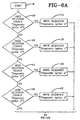
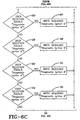
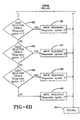
- Fig. 6 shows a routine called "OnExecute” which is executed when the user selects a sequence from a pull-down control on the user interface.
- the selections displayed on the pull-down include diagnostic sequences on any of the up to sixteen connected smart ignitors. This routine performs the diagnostic sequence on the smart ignitor selected.
- the routine called "OnExecute” is executed starting at block 9 when the user selects a sequence from a pull-down menu on the user interface.
- the selections displayed on the pull-down menu include diagnostic sequences on any one or combination of the smart ignitors 103.
- Block 10 if the "Diagnostic Ignitor 0" selection was chosen then the software and electronic hardware writes the sequence for diagnostic ignitor number 0 to ignitor 0 in block 11. The same conditional logic is applied in blocks 12 through 39. If none of the selections in blocks 10, 12, 19, 16, 18, 20, 22, 24, 26, 28, 30, 32, 34, 36, or 38 are true, then block 40 is executed in that the software and electronic hardware writes the sequence for diagnostic ignitor number F (that is, ignitor number 15). After blocks 11, 13, 15, 17, 19, 21, 23, 25, 27, 29, 31, 33, 35, 37 or 39 are executed then the routine exits in block 41.
- Fig. 7 shows a routine called "OnExecuteWrite" that is executed when the user initiates the sequence list control on the user interface is activated.
- Binary information that is to be sent to the MOSI serial data hardware node is stored in a MOSI software array (MOSI is the TTL (transistor-transistor logic) level serial command and data sent to the master ASIC and, when applicable, is sent by the master ASIC to one or more of the smart ignitors. Then the MOSI information is arranged so that the MSB (most significant bit) is sent to the master ASIC first. Then the pulse train length and logic of the SPI Clock is programmed and stored in the SPI Clock array. Next, the logic levels of the /CE signal is set up in the CE array.
- MOSI is the TTL (transistor-transistor logic) level serial command and data sent to the master ASIC and, when applicable, is sent by the master ASIC to one or more of the smart ignitors.
- MOSI is the TTL (transistor-transistor logic) level serial command and data sent to the master ASIC and, when applicable, is sent by the master ASIC to one or more of the smart ignitors.
- the format of the MOSI information is arranged so that the MSB (most significant bit) is sent to the master ASIC 102 first.
- the pulse train length and logic of the SPI Clock is programmed and stored in the SPI Clock array.
- the SPI Clock is the serial TTL pulses that are sent to the master ASIC with the MOSI signals to supply the required timing for the communications.
- the logic levels of the /CE signal (handshaking) is set up in the CE array.
- the /CE signal supplies chip enable logic information to the master ASIC.
- the logic levels of the D_C signal is set up in the D_C array.
- the D_C signal supplies data/command logic information the master ASIC.
- the contents of the MOSI software array, SPI Clock array, CE array, and the D_C array is stored in the data array.
- the routine exits in block 49.
- FIG. 3 is the smart ignitor SPI Bus Waveform showing data captured by a logic analyzer for the "Bus On" command sent via the MOSI serial data node referenced to the SPI clock for timing.
- the master ASIC output is seen in this figure in the MISO serial data node.
- FIG. 4 shows the smart ignitor.
- the master ASIC output is seen in this figure in the MISO serial data node.
- Fig. 8 shows a subroutine called “FlashWrt” that is executed when the user initiates the control button "EXECUTE” on the user interface.
- the contents of RAM #1 is cleared to remove any previously stored information and the electronic hardware for RAM #2 read functions are initialized. Then the content of the software data array is copied to the RAM #1 electronic hardware component. Then the content of the software delay functions is copied to the electronic delay hardware components. Then the binary contents of RAM #1 are sent by the electronic hardware to the inputs of the master ASIC.
- the subroutine called “FlashWrt” is executed when the user initiates the control button "EXECUTE" on the user interface. The routine starts at block 50.
- RAM #1 202 is cleared to remove any previously stored information and the electronic hardware for RAM #2 203 read functions are initialized.
- the contents of the software data array in the electronic information processor 100 is copied to RAM #1.
- the contents of the software delay functions are copied to the electronic delay hardware components 204.
- the binary contents of RAM #1 are sent by the electronic hardware to the master ASIC 201. The routine exits in block 55.
- Fig. 9 shows the software logic flow that starts the functions that read and store the binary output of the master ASIC into RAM #2.
- the routine starts at block 56.
- the "read data" routine is called as shown in block 58. If the condition is FALSE, the condition is retested. This routine exits after the return of the "read data" routine as shown in block 59.
- Fig. 10 shows logic flow that copies the binary contents of RAM #2 to the computer. This logic sequence is executed after the completion of the electronic hardware transfer of binary information from the master ASIC to electronic component RAM #2.
- the software initializes electronic hardware the computer uses to copy the information contents of RAM #2 into the computer. Then the information stored on RAM #2 is copied into a software data array. Next the software sorts the data into either MOSI or MISO. The software displays and processes the MOSI and MISO data as required.
- the software initializes electronic hardware 223 the electronic information processor uses to copy the information contents of RAM #2 into the electronic information processor.
- the information stored on RAM #2 is copied into a software data array.
- the software sorts the data into either MOSI (the write data echoed back from the master ASIC) or MISO (data response from the master ASIC or from the smart ignitors through the master ASIC).
- the software displays and processes the MOSI and MISO data as required. Some requirements may result in both MOSI and MISO data displayed on the computer screen, stored in files, databases, transferred through computer networks, or other operations. Data processing may include, but is not limited to, transferring operation status to the user or users by means of "PASS or FAIL" indications including text, light indicators, or accept/reject of the smart ignitor components or system.
- the routine exits in block 65.
- the prototype was made using discrete components that were interconnected with wire-wrap. However; it is understood that the same functions can be accomplished using microprocessor or microcontroller devices or any other suitable devices.
Landscapes
- Engineering & Computer Science (AREA)
- Mechanical Engineering (AREA)
- Air Bags (AREA)
Claims (8)
- Steuersystem für intelligente Zünder zum Steuern von intelligenten Zündern, umfassend:einen Prozessor für elektronische Information (100), der Ausgangstakt-, Daten-, und Handshaking-Signale an eine erste Speichereinrichtung (202) zuführt;eine elektronische Kommunikationsausgabe-Schaltungsanordnung (210), die Ausgangstakt-, Daten-, und Handshaking-Signale durch Lesen von Daten aus der ersten Speichereinrichtung (202) heraus für eine Kommunikation mit einer Master-ASIC (102), die mit einer Vielzahl von intelligenten Zündern (103) über einen Datenbus (206) kommuniziert, erzeugt,wobei die elektronische Kommunikationsausgabe-Schaltungsanordnung (210) umfasst:eine Datenschnittstellen-Schaltungsanordnung, die den Prozessor (100) für elektronische Information mit der ersten Speichereinrichtung verbindet;eine Datenschnittstellen-Schaltungsanordnung zum Verbinden der Master-ASIC (102) mit der ersten Speichereinrichtung (202), undeine Steuerschaltungsanordnung, die die Funktionen der Schnittstellen-Schaltungsanordnung und der ersten Speichereinrichtung (202) steuert; undeine elektronische Kommunikationseingabe-Schaltungsanordnung (211), die Daten- und Handshaking-Signale von der Master-ASIC (102) elektronischen Schaltung einer zweiten Speichereinrichtung (203) eingibt, umfassend:eine Datenschnittstellen-Schaltungsanordnung, die den Prozessor (100) für elektronische Information mit der zweiten Speichereinrichtung (203) verbindet;eine Datenschnittstellen-Schaltungsanordnung zum Verbinden der Master-ASIC (102), mit der zweiten Speichereinrichtung (203), undeine Steuerschaltungsanordnung, die die Funktionen der Schnittstellen-Schaltungsanordnung und der zweiten Speichereinrichtung (203) steuert.
- Steuersystem für intelligente Zünder nach Anspruch 1, ferner umfassend eine Master-ASIC (102) zum Zuführen von Energie an einen intelligenten Zünder (103) und zum Bereitstellen von bidirektionalen Kommunikationen mit einem intelligenten Zünder.
- Steuersystem für intelligente Zünder nach Anspruch 2, ferner umfassend eine Vielzahl von intelligenten Zündern (103), die in einer Schaltungskommunikation mit der Master-ASIC (102) über einen Zünderbus (206) sind.
- Steuersystem für intelligente Zünder nach Anspruch 1, wobei der Prozessor (100) für elektronische Information aus der Gruppe gewählt wird, die besteht aus Computern, Mikrocomputern, ASICs und programmierbaren digitalen und analogen Logikcontrollern mit Speichern.
- Steuersystem für intelligente Zünder nach Anspruch 1, wobei jede Speichereinrichtung (202, 203) aus der Gruppe gewählt ist, die besteht aus Flash-Speichern, EPROMs, EEPROMs, PROMs, ROMs, statischen Speichern mit wahlfreiem Zugriff und Speichern mit dynamischen wahlfreiem Zugriff.
- Steuersystem für intelligente Zünder nach Anspruch 1, wobei der Prozessor (100) für elektronische Information einen Eingang von einem Schalter oder Timer empfängt.
- Steuersystem für intelligente Zünder nach Anspruch 3, ferner umfassend eine Schaltung (212), die analoge Spannungen und Wellenformen von dem Zünderbus (206) digitalisiert, die digitalisierten Daten in einer dritten Speichereinrichtung (207) speichert, und dann die digitalisierten Daten an den Prozessor (100) für elektronische Information herauflädt.
- Steuersystem für intelligente Zünder nach irgendeinem der vorangehenden Ansprüche, wobei das System in einem Fahrzeug angeordnet ist und der Prozessor (100) für elektronische Information einen Eingang von wenigstens einem Sensor zum Erfassen eines Unfalls oder von Bedingungen, die eine hohe Wahrscheinlichkeit eines bevorstehenden Unfalls anzeigen, empfängt.
Applications Claiming Priority (3)
| Application Number | Priority Date | Filing Date | Title |
|---|---|---|---|
| US598860 | 2000-06-21 | ||
| US09/598,860 US6275756B1 (en) | 2000-06-21 | 2000-06-21 | Smart ignitor control system |
| PCT/US2001/000761 WO2001098113A1 (en) | 2000-06-21 | 2001-01-10 | Smart ignitor control system |
Publications (2)
| Publication Number | Publication Date |
|---|---|
| EP1309472A1 EP1309472A1 (de) | 2003-05-14 |
| EP1309472B1 true EP1309472B1 (de) | 2006-03-15 |
Family
ID=24397216
Family Applications (1)
| Application Number | Title | Priority Date | Filing Date |
|---|---|---|---|
| EP01901940A Expired - Lifetime EP1309472B1 (de) | 2000-06-21 | 2001-01-10 | Steuersystem für intelligente zünder |
Country Status (5)
| Country | Link |
|---|---|
| US (1) | US6275756B1 (de) |
| EP (1) | EP1309472B1 (de) |
| AU (1) | AU2001227792A1 (de) |
| DE (1) | DE60117959T2 (de) |
| WO (1) | WO2001098113A1 (de) |
Families Citing this family (14)
| Publication number | Priority date | Publication date | Assignee | Title |
|---|---|---|---|---|
| US7752970B2 (en) | 2000-09-06 | 2010-07-13 | Ps/Emc West, Llc | Networked electronic ordnance system |
| US7644661B1 (en) * | 2000-09-06 | 2010-01-12 | Ps/Emc West, Llc | Networked electronic ordnance system |
| US6490976B1 (en) | 2001-08-22 | 2002-12-10 | Breed Automotive Technology, Inc. | Smart igniter communications repeater |
| US6588342B2 (en) * | 2001-09-20 | 2003-07-08 | Breed Automotive Technology, Inc. | Frequency addressable ignitor control device |
| DE10149119C1 (de) * | 2001-10-05 | 2002-12-05 | Bosch Gmbh Robert | Vorrichtung zum Anschluß an eine Leitung |
| JP2004122927A (ja) * | 2002-10-02 | 2004-04-22 | Denso Corp | 車両乗員検知装置 |
| DE102004056475A1 (de) * | 2004-11-23 | 2006-05-24 | Conti Temic Microelectronic Gmbh | Steuergerät für ein Fahrzeug, insbesondere für eine Sicherheitseinrichtung eines Fahrzeugs |
| US20080086250A1 (en) * | 2006-10-05 | 2008-04-10 | Renesas Technology America, Inc. | Squib driver circuit diagnostic system and method |
| DE102007023322B4 (de) * | 2007-05-16 | 2017-05-18 | Volkswagen Ag | Personenschutzsystem für ein Fahrzeug und zugehöriges Verfahren |
| US8213151B2 (en) * | 2008-12-31 | 2012-07-03 | Pacific Scientific Energetic Materials Company (California), LLC | Methods and systems for defining addresses for pyrotechnic devices networked in an electronic ordnance system |
| DE102013000116B4 (de) * | 2013-01-05 | 2022-04-21 | Volkswagen Aktiengesellschaft | Verfahren zur Identifikation von pyrotechnischen Einheiten in einem Kraftfahrzeug |
| CN109196300B (zh) * | 2016-05-13 | 2021-05-28 | 均胜安全系统收购有限责任公司 | 智能引爆器组件 |
| US9810515B1 (en) | 2017-02-03 | 2017-11-07 | Pacific Scientific Energetic Materials Company (California) LLC | Multi-level networked ordnance system |
| KR102658538B1 (ko) * | 2019-04-23 | 2024-04-18 | 현대모비스 주식회사 | 차량용 에어백 구동장치 및 그 제어방법 |
Family Cites Families (18)
| Publication number | Priority date | Publication date | Assignee | Title |
|---|---|---|---|---|
| US6116639A (en) * | 1994-05-09 | 2000-09-12 | Automotive Technologies International, Inc. | Vehicle interior identification and monitoring system |
| US4843964A (en) | 1988-02-01 | 1989-07-04 | The United States Of America As Represented By The United States Department Of Energy | Smart explosive igniter |
| US5546307A (en) | 1989-05-30 | 1996-08-13 | Trw Vehicle Safety Systems Inc. | Method and apparatus for discriminating vehicle crash conditions |
| US5261694A (en) * | 1991-06-14 | 1993-11-16 | Automotive Systems Laboratory, Inc. | Reconfigurable air bag firing circuit |
| JP3095569B2 (ja) | 1993-03-16 | 2000-10-03 | 富士通テン株式会社 | 車両のエアバッグシステムのスクイブ点火回路 |
| JP2661863B2 (ja) | 1993-10-29 | 1997-10-08 | 富士通テン株式会社 | 車両のエアバッグシステムにおけるスクイブライン系診断装置 |
| KR100199641B1 (ko) * | 1993-11-15 | 1999-06-15 | 가아디스 비이 소렌센 | 탑승자 보호장치용 작동장치 |
| DE19531899B4 (de) | 1995-08-30 | 2004-11-25 | Robert Bosch Gmbh | Elektronische Einrichtung und Betriebsverfahren für diese |
| US5722687A (en) | 1996-02-09 | 1998-03-03 | Siemens Automotive Corporation | Airbags squib with temperature bias |
| FR2744862B1 (fr) | 1996-02-12 | 1998-04-30 | Motorola Semiconducteurs | Circuit de commande de l'alimentation electrique d'un element allumeur |
| US5666065A (en) * | 1996-05-22 | 1997-09-09 | Delco Electronics Corp. | Fast acting FET test circuit for SIR diagnostics |
| US5872460A (en) * | 1996-10-04 | 1999-02-16 | Delco Electronics Corp. | Fast acting FET test circuit with current detection for SIR diagnostics |
| DE19721839A1 (de) | 1997-04-15 | 1998-10-22 | Dynamit Nobel Ag | Elektronischer Zünder |
| US5938708A (en) * | 1997-07-03 | 1999-08-17 | Trw Inc. | Vehicle computer system having a non-interrupt cooperative multi-tasking kernel and a method of controlling a plurality of vehicle processes |
| US5954360A (en) * | 1997-09-18 | 1999-09-21 | Breed Automotive Technology, Inc. | Vehicle occupant sensing apparatus and method |
| US6036225A (en) * | 1998-07-01 | 2000-03-14 | Trw Inc. | Method and apparatus for controlling an actuatable restraint device using crash severity indexing |
| US6026340A (en) * | 1998-09-30 | 2000-02-15 | The Robert Bosch Corporation | Automotive occupant sensor system and method of operation by sensor fusion |
| US6166452A (en) | 1999-01-20 | 2000-12-26 | Breed Automotive Technology, Inc. | Igniter |
-
2000
- 2000-06-21 US US09/598,860 patent/US6275756B1/en not_active Expired - Lifetime
-
2001
- 2001-01-10 EP EP01901940A patent/EP1309472B1/de not_active Expired - Lifetime
- 2001-01-10 WO PCT/US2001/000761 patent/WO2001098113A1/en not_active Ceased
- 2001-01-10 DE DE60117959T patent/DE60117959T2/de not_active Expired - Fee Related
- 2001-01-10 AU AU2001227792A patent/AU2001227792A1/en not_active Abandoned
Also Published As
| Publication number | Publication date |
|---|---|
| EP1309472A1 (de) | 2003-05-14 |
| US6275756B1 (en) | 2001-08-14 |
| AU2001227792A1 (en) | 2002-01-02 |
| DE60117959T2 (de) | 2006-12-07 |
| DE60117959D1 (de) | 2006-05-11 |
| WO2001098113A1 (en) | 2001-12-27 |
Similar Documents
| Publication | Publication Date | Title |
|---|---|---|
| US6275756B1 (en) | Smart ignitor control system | |
| US6166452A (en) | Igniter | |
| US8213151B2 (en) | Methods and systems for defining addresses for pyrotechnic devices networked in an electronic ordnance system | |
| US6889610B2 (en) | Ordnance firing system | |
| EP1497608B1 (de) | Geschützzündsystem | |
| KR100511120B1 (ko) | 가스 발생기에서 점화기와 차량측 커넥터 사이의 오접속을 판단하는 방법 | |
| EP1529696B1 (de) | Zündpille | |
| JP2000501496A (ja) | 電子起爆装置 | |
| JPWO1995000369A1 (ja) | 乗員保護システムの起動装置 | |
| JP3803636B2 (ja) | バス接続用点火装置 | |
| US6564715B2 (en) | Frequency addressable ignitor control device | |
| JPH11253922A (ja) | 火薬点火器を持つ乗客保護装置用廃棄処理装置及び廃棄処理方法 | |
| JP6289490B2 (ja) | 膨張可能な拘束具用の2重作動システム | |
| Boys | Safe-by-wire: the leading edge in vehicle airbag control | |
| JP4128518B2 (ja) | 着火装置 | |
| Rainwater et al. | Development of Smart Initiators | |
| JP4128519B2 (ja) | 着火装置 | |
| JP2005175672A (ja) | 点火システム | |
| JP2005172311A (ja) | 点火システム | |
| MXPA01007320A (en) | Igniter | |
| JP2001130366A (ja) | 爆薬を用いる装置および車両の乗員保護装置 |
Legal Events
| Date | Code | Title | Description |
|---|---|---|---|
| PUAI | Public reference made under article 153(3) epc to a published international application that has entered the european phase |
Free format text: ORIGINAL CODE: 0009012 |
|
| 17P | Request for examination filed |
Effective date: 20020829 |
|
| AK | Designated contracting states |
Designated state(s): AT BE CH CY DE DK ES FI FR GB GR IE IT LI LU MC NL PT SE TR |
|
| RBV | Designated contracting states (corrected) |
Designated state(s): DE ES FR GB IT |
|
| RAP1 | Party data changed (applicant data changed or rights of an application transferred) |
Owner name: KEY SAFETY SYSTEMS, INC. |
|
| 17Q | First examination report despatched |
Effective date: 20041122 |
|
| GRAP | Despatch of communication of intention to grant a patent |
Free format text: ORIGINAL CODE: EPIDOSNIGR1 |
|
| GRAS | Grant fee paid |
Free format text: ORIGINAL CODE: EPIDOSNIGR3 |
|
| GRAA | (expected) grant |
Free format text: ORIGINAL CODE: 0009210 |
|
| AK | Designated contracting states |
Kind code of ref document: B1 Designated state(s): DE ES FR GB IT |
|
| PG25 | Lapsed in a contracting state [announced via postgrant information from national office to epo] |
Ref country code: IT Free format text: LAPSE BECAUSE OF FAILURE TO SUBMIT A TRANSLATION OF THE DESCRIPTION OR TO PAY THE FEE WITHIN THE PRESCRIBED TIME-LIMIT;WARNING: LAPSES OF ITALIAN PATENTS WITH EFFECTIVE DATE BEFORE 2007 MAY HAVE OCCURRED AT ANY TIME BEFORE 2007. THE CORRECT EFFECTIVE DATE MAY BE DIFFERENT FROM THE ONE RECORDED. Effective date: 20060315 |
|
| REG | Reference to a national code |
Ref country code: GB Ref legal event code: FG4D |
|
| REF | Corresponds to: |
Ref document number: 60117959 Country of ref document: DE Date of ref document: 20060511 Kind code of ref document: P |
|
| PG25 | Lapsed in a contracting state [announced via postgrant information from national office to epo] |
Ref country code: ES Free format text: LAPSE BECAUSE OF FAILURE TO SUBMIT A TRANSLATION OF THE DESCRIPTION OR TO PAY THE FEE WITHIN THE PRESCRIBED TIME-LIMIT Effective date: 20060626 |
|
| ET | Fr: translation filed | ||
| PLBE | No opposition filed within time limit |
Free format text: ORIGINAL CODE: 0009261 |
|
| STAA | Information on the status of an ep patent application or granted ep patent |
Free format text: STATUS: NO OPPOSITION FILED WITHIN TIME LIMIT |
|
| 26N | No opposition filed |
Effective date: 20061218 |
|
| PGFP | Annual fee paid to national office [announced via postgrant information from national office to epo] |
Ref country code: DE Payment date: 20090130 Year of fee payment: 9 |
|
| PGFP | Annual fee paid to national office [announced via postgrant information from national office to epo] |
Ref country code: GB Payment date: 20081211 Year of fee payment: 9 |
|
| PGFP | Annual fee paid to national office [announced via postgrant information from national office to epo] |
Ref country code: IT Payment date: 20090115 Year of fee payment: 9 |
|
| PGFP | Annual fee paid to national office [announced via postgrant information from national office to epo] |
Ref country code: FR Payment date: 20090106 Year of fee payment: 9 |
|
| GBPC | Gb: european patent ceased through non-payment of renewal fee |
Effective date: 20100110 |
|
| REG | Reference to a national code |
Ref country code: FR Ref legal event code: ST Effective date: 20100930 |
|
| PG25 | Lapsed in a contracting state [announced via postgrant information from national office to epo] |
Ref country code: FR Free format text: LAPSE BECAUSE OF NON-PAYMENT OF DUE FEES Effective date: 20100201 |
|
| PG25 | Lapsed in a contracting state [announced via postgrant information from national office to epo] |
Ref country code: DE Free format text: LAPSE BECAUSE OF NON-PAYMENT OF DUE FEES Effective date: 20100803 |
|
| PG25 | Lapsed in a contracting state [announced via postgrant information from national office to epo] |
Ref country code: GB Free format text: LAPSE BECAUSE OF NON-PAYMENT OF DUE FEES Effective date: 20100110 |
|
| PG25 | Lapsed in a contracting state [announced via postgrant information from national office to epo] |
Ref country code: IT Free format text: LAPSE BECAUSE OF NON-PAYMENT OF DUE FEES Effective date: 20100110 |