EP1308625B1 - Appareillage de commande d'un système de refroidissement pour compresseur - Google Patents
Appareillage de commande d'un système de refroidissement pour compresseur Download PDFInfo
- Publication number
- EP1308625B1 EP1308625B1 EP02017501A EP02017501A EP1308625B1 EP 1308625 B1 EP1308625 B1 EP 1308625B1 EP 02017501 A EP02017501 A EP 02017501A EP 02017501 A EP02017501 A EP 02017501A EP 1308625 B1 EP1308625 B1 EP 1308625B1
- Authority
- EP
- European Patent Office
- Prior art keywords
- fluid
- actuator
- summer
- cooling fluid
- arrangement according
- Prior art date
- Legal status (The legal status is an assumption and is not a legal conclusion. Google has not performed a legal analysis and makes no representation as to the accuracy of the status listed.)
- Expired - Lifetime
Links
Images


Classifications
-
- F—MECHANICAL ENGINEERING; LIGHTING; HEATING; WEAPONS; BLASTING
- F04—POSITIVE - DISPLACEMENT MACHINES FOR LIQUIDS; PUMPS FOR LIQUIDS OR ELASTIC FLUIDS
- F04C—ROTARY-PISTON, OR OSCILLATING-PISTON, POSITIVE-DISPLACEMENT MACHINES FOR LIQUIDS; ROTARY-PISTON, OR OSCILLATING-PISTON, POSITIVE-DISPLACEMENT PUMPS
- F04C29/00—Component parts, details or accessories of pumps or pumping installations, not provided for in groups F04C18/00 - F04C28/00
- F04C29/04—Heating; Cooling; Heat insulation
- F04C29/042—Heating; Cooling; Heat insulation by injecting a fluid
-
- F—MECHANICAL ENGINEERING; LIGHTING; HEATING; WEAPONS; BLASTING
- F04—POSITIVE - DISPLACEMENT MACHINES FOR LIQUIDS; PUMPS FOR LIQUIDS OR ELASTIC FLUIDS
- F04C—ROTARY-PISTON, OR OSCILLATING-PISTON, POSITIVE-DISPLACEMENT MACHINES FOR LIQUIDS; ROTARY-PISTON, OR OSCILLATING-PISTON, POSITIVE-DISPLACEMENT PUMPS
- F04C29/00—Component parts, details or accessories of pumps or pumping installations, not provided for in groups F04C18/00 - F04C28/00
- F04C29/0007—Injection of a fluid in the working chamber for sealing, cooling and lubricating
- F04C29/0014—Injection of a fluid in the working chamber for sealing, cooling and lubricating with control systems for the injection of the fluid
-
- F—MECHANICAL ENGINEERING; LIGHTING; HEATING; WEAPONS; BLASTING
- F04—POSITIVE - DISPLACEMENT MACHINES FOR LIQUIDS; PUMPS FOR LIQUIDS OR ELASTIC FLUIDS
- F04C—ROTARY-PISTON, OR OSCILLATING-PISTON, POSITIVE-DISPLACEMENT MACHINES FOR LIQUIDS; ROTARY-PISTON, OR OSCILLATING-PISTON, POSITIVE-DISPLACEMENT PUMPS
- F04C29/00—Component parts, details or accessories of pumps or pumping installations, not provided for in groups F04C18/00 - F04C28/00
- F04C29/02—Lubrication; Lubricant separation
- F04C29/026—Lubricant separation
Definitions
- the invention relates to an arrangement for controlling the cooling fluid flow in compressors, in particular in rotary compressors according to the preamble of patent claim 1 and a method according to the preamble of claim 17.
- the compressors mentioned here are in particular fluid-injected screw compressors. Since such machines are often used in changing locations, they are usually mobile or at least transportable. From these machines, the compressed process fluid is supplied via pneumatic consumers connected to lines, such as pneumatic tools, such as pneumatic hammers, pneumatic impact wrenches, compressed air grinders, and the like.
- the mentioned compressors such as oil-injected screw compressors, have been known for many years.
- a cooling fluid in particular oil is injected into the compression volume.
- the cooling fluid is used to cool the process fluid by dissipating the heat of compression in a separate cooling circuit and also to lubricate certain components of the compressor and to seal the compression volume.
- the process fluid air it is usually sucked from the environment and therefore usually contains a dependent on its temperature amount of gaseous water.
- a first problem to be considered in this case in the injection or return of the cooling fluid is the risk of falling below the dew point for the present in the process fluid air gaseous water.
- Condensed water can be emulsified to some extent with the cooling fluid, in particular the oil, or additionally injected or recycled as an additional phase. This is, among other things, associated with the following disadvantages: reduction of the lubricating properties of the cooling fluid, increased component corrosion and increased bearing wear in the compressor.
- a second, to be distinguished from the first problem arises when the process fluid, in particular the compressed air in the conduit path to the pneumatic device cools and thereby condenses water contained in the process fluid. This can cause corrosion in the pneumatic device. As a result, permanent damage can occur.
- a significant aggravation of the problem is when ice formation occurs within the consumer lines or within the pneumatic consumers due to the low ambient temperature and the cable routes to or in the pneumatic consumer thereby partially or completely blocked. These effects can be further enhanced by the expansion of the compressed air in the pneumatic consumer. This can lead to functional inactivity or even to total inability to operate the associated pneumatic consumers.
- a common technical control principle for controlling the temperature of a cooling fluid in compressors is given for example in EP 0 067 949 B1.
- a thermo slide determines here, whether cooling fluid is passed to the cooling via a fluid cooler or to increase the temperature at the fluid cooler.
- the control leads to a relatively constant temperature of the cooling fluid, wherein the temperature is chosen so that on the one hand falls below the dew point of the process fluid and on the other hand too great a load of the cooling fluid is avoided by a too high temperature.
- An analogous control is described for the field of internal combustion engines, for example in DE 91 05 021 U1.
- valve unit with a cooling fluid inlet and a cooling fluid outlet is described.
- the volume flow of the cooling fluid is also controlled in a bypass line bridging the fluid cooler, wherein a partial flow of the cooling fluid is always passed through the fluid cooler.
- the regulation takes place by means of a valve, which comprises two mutually acting actuators, wherein an actuator depending on the intake temperature and a second actuator in dependence the system temperature is working.
- a disadvantage of this design is, inter alia, that the valve unit is constructed in a complicated and trouble-prone manner and, furthermore, a minimum volume flow of the cooling fluid is conducted via the fluid cooler. It is thus constantly cooled and thus causes a lowering of the temperature of the process fluid.
- US Pat. No. 4,431,390 discloses a regulation in which a second bypass line is still provided past the fluid cooler.
- this second bypass line there is another valve, the pulse, driven by a processor, a certain amount of cooling fluid passes the fluid cooler over.
- These pulses are enabled by the processor in response to various parameters. This solution is therefore very complicated both because of the detection of the various parameters, the evaluation of the parameters and finally also because of the provision of a further bypass line.
- the pre-discussed solutions are primarily concerned with the problem of keeping the cooling fluid in the compressor itself at a temperature that prevent the condensation of water and thus the impairment of the cooling fluid and the compressor.
- the specified regulations are designed so that, in order to preserve the cooling fluid, a much higher temperature of the cooling fluid is avoided.
- the problem of the condensation of water in pneumatic consumers or consumer supply lines is not addressed.
- a solution variant is known from DE 36 01 816 A1.
- the compressed process fluid heated to about 60 ° C above the intake temperature of the compressor is cooled in an oversized aftercooler to a temperature about 10 ° C above the intake temperature.
- a significant portion of the water vapor present in the process fluid condenses and is eliminated by condensate.
- the compressed process fluid is reheated in a downstream heat exchanger, so that - influenced by the current, but assumed in the design as immutable environmental parameters - a fairly dry, about 60 ° C above the intake temperature heated, thus very hot process fluid is present.
- the present invention has for its object, a known arrangement for controlling the cooling fluid in compressors, starting from the prior art, to further develop so that in a simple, inexpensive and reliable construction, the condensation of water in both the cooling fluid and in reduce a consumer dispensed process fluid, in particular a condensation and freezing in the consumer even while maintaining high ease of use or possibly avoid.
- a core idea of the present invention is to provide a summer / winter operation actuator which overrides, in priority to the system control actuator in a summer position, the action of the system control actuator in a direction of action, in whole or in part, such that when the summer / summer activation is activated.
- Winter operation actuator of the partial flow of the guided over the fluid cooler cooling fluid and / or the injection amount of cooling fluid is increased or decreased by a fluid control means.
- the invention uses the context that the temperature of the process fluid at the system outlet is determined by the temperature of the cooling fluid, in particular corresponds approximately to the maximum temperature of the cooling fluid.
- a control of the temperature of the process fluid at the system output can therefore be achieved both by influencing the injection temperature and the injection quantity of the cooling fluid.
- the arrangement can be initially set so that the process fluid is cooled less and supplied to the consumer or consumer lines with a comparatively high temperature , The cooling occurring within the consumer lines or to the consumer then usually enough to ensure a comfortable working for a consumer operating on the consumer. Only at Hot ambient temperature, where the cooling effect of the process fluid on the way to the consumer may no longer be so large, according to the invention, the process fluid is cooled even further by operating a summer / winter operation actuator.
- the summer / winter operation actuator or, more generally, an ambient temperature-compensation actuator is provided to compensate for a reduced or increased cooling effect as possible by a lower or higher ambient temperature.
- the use of the terms summer and winter in connection with summer / winter operation actuator or summer / winter position is for better understanding and generally means two different types of environmental conditions, on the one hand colder and on the other hand warmer ambient conditions.
- the winter operation aims to avoid falling below the dew point of the process fluid up to the consumer, whereas the summer operation should prevent exceeding a maximum temperature at the consumer.
- the summer / winter operating actuator which, more generally, may also be referred to as an ambient temperature compensation actuator for compensating for cooling effects by a higher or lower ambient air, comprises a manual operating device, via which the summer / Winter operation actuator actuate, in particular between two positions, namely a summer position and a winter position can switch.
- the manual actuating device can be designed in different ways, for example a hand lever, a dial, possibly with a reduction gear and another suitable actuating device.
- the summer / winter operating actuator comprises an actuating shaft with an eccentric, wherein the eccentric acts on the fluid control means via a control element.
- the actuating shaft can be, for example, in operative connection with the manual actuating device or driven by an electric motor, pneumatically or hydraulically.
- the summer / winter operation actuator is operatively connected to an outside air thermocouple, wherein the outside air thermoelement activates the summer / winter operation actuator depending on the outside or ambient temperature.
- the summer / winter operating actuator is operatively connected to a thermal sensor which activates the summer / winter operating actuator as a function of the outside temperature.
- the advantage over a manual actuator is that an automatic compensation of an increased or reduced cooling effect takes place in colder or warmer ambient air, whereas, in the case of a manual actuator, the activation of the summer / winter operation actuator by the operator Has.
- system control actuator and the summer / winter operation actuator are operatively connected to a common fluid control means, wherein the fluid control means adjusts the partial flow of the cooling fluid passed through the fluid cooler and wherein the operative connection of the system control actuator with the fluid control means when actuated of the summer / winter operation actuator is completely or partially canceled in the direction of a summer position in a direction of action.
- the control of the cooling of the process fluid can be carried out in a particularly simple and effective manner, when both system control actuator and summer / winter operation actuator act on the fluid flow of the cooling fluid via a common fluid control means.
- the priority circuit considered to be appropriate realized in a particularly simple manner characterized in that the summer / winter operation actuator can be brought if necessary in a position in which he cancels the action of the system control actuator in a direction of action wholly or partially. It is thus possible, as described above, first to set the system to a relatively high temperature of the process fluid and Make corrections at high ambient temperature via the summer / winter operation actuator.
- system control actuator and summer / winter operating actuator are arranged axially zueinender, which allows a relatively simple structure.
- a displaceably mounted control element and the fluid control means are integrally formed as a control cylinder.
- the slidably mounted control element is a force transfer means which does not necessarily have to be surrounded by the fluid flow.
- the one-piece control cylinder engages in the fluid flow and at the same time comprises sealing surfaces in order to effect a seal with respect to the fluid channel.
- system control actuator on, preferably housed in the control and is supported against a fixed against all positions of the summer / winter operation actuator abutment surface.
- system control actuator depending on the position of the summer / winter operation actuator in a direction of action only partially, u.U. also no longer effective with respect to an adjustment of the fluid control agent.
- the summer / winter operating actuator can be switched between at least two positions. He may also take one or more intermediate positions or, which is particularly preferred in terms of control technology, continuously changeable between a first position (winter position) and a second position (summer position).
- the concept of the present invention in a logical inversion, namely to control the process fluid in a compressor through the arrangement for controlling the flow of cooling fluid first at a rather low, condensation-prone temperature and by means of a summer / winter operation actuator or compensation actuator for critical ambient temperatures, namely cool ambient temperatures to provide a priority attitude that generates a process fluid having an elevated temperature by influencing the cooling fluid flow.
- the temperature of the process fluid can be influenced by the concept of a priority circuit according to the present invention not only by the control of the temperature of the cooling fluid injected into the compressor, but additionally or alternatively by changing the volume flow of the cooling fluid.
- the fluid control means is positioned at a node between a bypass line bridging the fluid cooler and a cooling line associated with the fluid cooler, such that as the cooling fluid flow passed through the fluid cooler increases, the flow of fluid through the bypass line is simultaneously increased is reduced.
- the fluid control means may be positioned both at a node located in the fluid direction upstream of the fluid cooler and at a node downstream of the fluid cooler in the fluid direction. The attachment of the fluid control means in a node is felt to be particularly advantageous because at the same time a reduction of the other partial flow and thus a very effective influence is effected by increasing the one partial flow.
- a method for controlling the cooling fluid in compressors, in particular in rotary compressors is claimed, which is characterized in particular by the fact that to prevent condensation and / or ice formation in the connected consumers or consumer supply lines at low outside air temperatures, in particular, when falling below a certain outside air temperature T G , which is interrupted or reduced via the fluid cooler guided partial flow of the cooling fluid.
- the partial flow guided via the fluid cooler is first reduced independently of the outside air temperature and increased again only at high outside air temperatures, in particular when a certain outside air temperature T G is exceeded, via the fluid cooler.
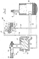
- FIG. 1 schematically shows a compressor system 31 with a compressor 12 and an arrangement connected thereto for controlling the cooling fluid flow 30.
- the compressor 12 is driven via a drive shaft 32 by a (not shown) drive.
- ambient air is sucked in via a suction filter 33 and passes through an intake 34 into the compression chamber 35.
- a cooling fluid in the present case, oil is supplied.
- the oil-based cooling fluid lubricates, improves sealing, and cools the aspirated and compressed process fluid, which is in the form of compressed air.
- the compressed air / oil mixture is fed via a cooling fluid / process fluid line 37 to a fluid separator 38.
- the cooling fluid / process fluid mixture which is present here as an oil / compressed air mixture, separated.
- the process fluid obtained in the form of compressed air is supplied to an output line 39 and from there via consumer lines (not shown) to one or more consumers.
- the in the fluid separator 38 recovered, in the form of oil cooling fluid passes via a return line 40 to a first node 41, at which a cooler line 21 leads to a fluid cooler 14 and from there to a second node 42.
- a bypass line 20 connects the first node 41 and the second node 42 directly, bypassing the fluid cooler 14.
- the second node 42 is defined in a valve unit 43 in the present embodiment.
- the valve unit 43 may preferably be mounted directly on the compressor block or on the fluid separator 38 or on the fluid cooler 14.
- the valve unit 43 includes a system control actuator 15 which is operatively connected to a fluid thermocouple 29 and controls a fluid control means 19 based on the temperature of the cooling fluid (see Fig. 2).
- the fluid control means reduces the partial flow guided via the bypass line and at the same time increases the partial flow conducted via the fluid cooler 14 so that the cooling fluid is cooled more strongly overall by the fluid cooler 14.
- the cooling fluid cools, the flow of the cooling fluid guided through the fluid cooler is reduced by the fluid control means; at the same time, the partial flow of the cooling fluid passed via the bypass line 20 past the fluid cooler 14 is increased, so that the cooling fluid as a whole is less cooled.
- the cooling fluid as shown in the present case, can still be guided via an oil filter 44 and is reintroduced into the compression space 35 of the compressor 12 via the already mentioned supply line 36.
- the arrangement according to the invention for controlling the cooling fluid flow is integrated in a circuit leading above the compression space 35 of the compressor 12 and the fluid separator 38.
- a cooling fluid inlet 11 of the arrangement for controlling the cooling fluid flow 30 is defined by the already mentioned return line 40 and a cooling fluid outlet 13 by the feed line 36, also already mentioned.
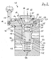
- valve unit 43 initially comprises a but valve block 45 with a central bore 46, a first lateral bore 47, a second lateral bore 48 and a third lateral bore 49.
- the central bore 46 has an upper portion 50, a middle portion 51 and a lower portion 52.
- the lower portion 52 defines a central valve interior 53.
- the middle portion is widened from the lower portion 52 and the upper portion 50 to form a valve chamber 54.
- the valve chamber 54 is in fluid communication with the supply line 36 via the first lateral bore 47 to the compression space 35 of the compressor 12.
- the central valve interior 53 communicates via the second lateral bore 48 in fluid communication with the bypass line 20.
- the upper portion 50 of the central bore 46 in the valve block 45 defines an upper valve interior 55, via the third lateral bore 49 with the fluid cooler 14 is in fluid communication.
- the formed at its lower end fluid control means is provided to lock either the guided over the fluid cooler 14 partial flow, or guided via the bypass line 20 partial flow or set a certain mixing ratio between these two partial flows.
- the formed as a fluid control means 19 part of the control cylinder 25 has a first circumferential sealing surface 56.
- the second circumferential sealing surface 57 prevents the escape of oil.
- the first peripheral sealing surface 56 causes in a first or second end position of the control cylinder 25, except for a leakage, complete shut-off either of the guided via the fluid cooler 14 partial flow or guided through the bypass line 20 partial flow.
- the displacement of the control cylinder 25 between said end positions or in intermediate positions is done as follows. First, the control cylinder 25 biased by a arranged in the central valve interior 53 coil spring 58 under bias in an upper, here the shut-off over the fluid cooler 14 partial flow shut-off position. A displacement of the control cylinder 25 from this end position can now be done either via a system control actuator 15 or a summer / winter operation actuator 16.
- the system control actuator 15 is supported, which is activated by the fluid thermocouple. Upon heating of the fluid thermocouple 29, a substance accommodated therein expands and pushes the system control actuator 15 out of the fluid thermocouple 29.
- the system control actuator 15 is supported via an adjusting piston 27 against a fixed relative to the valve block 45 abutment surface 26, so that upon expansion of housed in the fluid thermocouple 29 substance of the control cylinder 25 in total against the pressure of the coil spring 58 in the direction of the central valve interior 53 is moved, thus releasing an upper annular gap 59 between the upper valve interior 55 and the valve chamber 54.
- cooling fluid can now enter the valve chamber 54 from the fluid cooler 14 and, after mixing with cooling fluid, is led out of the bypass line 20 via the supply line 56 into the compression chamber 35 of the compressor 12.
- the control cylinder 25 moves further in the direction of the central valve interior 53, the upper annular gap 59 increases, at the same time a corresponding lower annular gap 60 between the valve chamber 54 and the central valve interior 53 becomes steadily smaller. The result is that an ever greater proportion of the flow from the fluid cooler 14 and at the same time in ever smaller fluid flow from the bypass line 20 can enter the valve chamber 54. If the control cylinder 25 moves still further toward the central valve interior 53, then the first circumferential sealing surface 56 closes the lower annular gap 60, the first circumferential sealing surface 56 again sealingly coming into contact with the wall of the central bore 46.
- the control cylinder 25 can also be displaced by the already mentioned summer / winter operation actuator 16 as follows.
- An outside air thermocouple 18 is disposed in a valve cover 61 axially of the system control actuator 15, the summer / winter operation actuator 16 facing the valve chamber 54 facing the system control actuator 15 is slidably mounted within the outside air thermocouple 18. Also in the outside air thermocouple is housed under increasing temperature expands fabric which causes expansion of the summer / winter operation actuator 16. The outside air thermocouple 18 is either directly in contact with ambient air or receives an approximately representative of the ambient air temperature.
- a control crown 62 is also mounted displaceably axially for the summer / winter operation actuator 16 and the system control actuator 15.
- the control crown 62 preferably has a plurality of webs 63 which pass through associated recesses 64 in a cover plate 65 covering the central bore 46 of the valve block 45. Via the cover plate 65, the valve cover 61 is connected to the valve block 45.
- the distal ends of the webs 63 are in contact with the control cylinder 25.
- the summer / winter operation actuator 16 is located on the other side via an adjusting piston 28 on the control crown 62 at.
- the summer / winter operation actuator 16 is pushed out of the outside air thermocouple in the direction of the valve chamber 54 and presses on the control cylinder 62 via the control crown 62.
- the summer / winter operating actuator 16 causes the control crown 62, and thus the control cylinder 25, to continue to move downwards, ie. shifted to the central valve interior 53 and can finally reach an end position in which the lower annular gap 60 is closed, so that no partial flow is passed through the bypass line 20. In this position, the effect of the system control actuator 15 is completely off.
- the summer / winter operating actuator 16 merely predetermines a minimum position for the width of the upper annular gap 59, ie for the amount of the partial flow conducted via the fluid cooler 14. However, should the cooling fluid so heat that the system control actuator 15 is pushed out of the fluid thermocouple 29 so far that it exerts a force on the contact surface 26, the control cylinder 25 will continue to move in the direction of the central valve interior 53 and thus further increase the upper annular gap 59. However, the system control actuator 15 is unable to reduce the width of the upper annular gap 59 set by the summer / winter operation actuator 16.
- FIG. 3 an alternative embodiment of a valve unit for an arrangement for controlling the cooling fluid flow according to the invention is shown.
- the two embodiments differ essentially in that the summer / winter operating actuator 16 is not acted upon by an outside air thermocouple 18 in the embodiment according to FIG. 3, but instead comprises a manual operating device, in the present case a hand lever 17, which acts via an actuating shaft 22 and an integrally formed on the actuating shaft 22 eccentric 23 - for example, at a 120 ° rotation of the actuating shaft 22 - in a similar manner as the webs 63 of the control crown 62 on the control cylinder 25.
- a manual operating device in the present case a hand lever 17, which acts via an actuating shaft 22 and an integrally formed on the actuating shaft 22 eccentric 23 - for example, at a 120 ° rotation of the actuating shaft 22 - in a similar manner as the webs 63 of the control crown 62 on the control cylinder 25.
- valve block 45 is performed in the embodiment of FIG. 3 slightly longer and has a fourth lateral bore 66 which traverses the central bore 46 and defines on one side of the central bore 46 has a through hole and on the opposite side of a blind bore.
- the actuating shaft 22 is inserted above the control cylinder 25.
- the actuating shaft 22 is held by means of a bearing disc 67 in the bore 66.
- the eccentric 23 on the actuating shaft 22 is defined by two eccentric portions 68, 69 which lie on both sides of a circumferential groove 70.
- the circumferential groove 70 defines in the present embodiment, the abutment surface 26 for the adjusting piston 27 of the system control actuator 15 and is characterized in that the position of this contact surface remains constant upon actuation of the actuating shaft 22. While the defined by the circumferential groove 70 contact surface 26 remains constant in its height position upon rotation of the actuating shaft 22, the eccentric 68, 69 push the control cylinder 25 in the direction of the central valve interior 43, so that the upper annular gap 59 depending on the dimensions of the eccentricity the eccentric 68, 69 increases. In the present embodiment, at a 120 ° rotation of the actuating shaft 22, the lower annular gap 60 is closed, so that is blocked in the guided over the bypass line partial flow. The effect of the system control actuator 15 is also turned off in this end position.
- FIG. 4 the embodiment of a valve unit of FIG. 3 is shown in a second position, in which case the pivoted by 120 ° hand lever 17 is not shown.
- the upper annular gap 59 is completely opened, wherein at the same time the lower annular gap 60 is closed by the control element 24.
- the contact surface 26 of the eccentric 23 of the actuating shaft 22 presses the control cylinder 25 and thus the control element 24 against the coil spring 58, so that the upper annular gap 59 is opened and the lower annular gap 60 is closed.
- the adjusting piston 27 of the System horraktuators 15 is no longer supported in the illustration shown against the contact surface 26 of the actuating shaft 22, so that the Systemberichtaktuator 15 in the position shown no influence on the control 24 more exercises.
Landscapes
- Engineering & Computer Science (AREA)
- Mechanical Engineering (AREA)
- General Engineering & Computer Science (AREA)
- Applications Or Details Of Rotary Compressors (AREA)
- Compressor (AREA)
- Control Of Positive-Displacement Air Blowers (AREA)
- Control Of Positive-Displacement Pumps (AREA)
- Fluid-Pressure Circuits (AREA)
- Structures Of Non-Positive Displacement Pumps (AREA)
Claims (17)
- Dispositif pour commander le flux de fluide de refroidissement dans des compresseurs, en particulier dans des compresseurs à rotation, comme les compresseurs à vis, le dispositif comprenant:- une entrée du fluide de refroidissement (11) pour du fluide de refroidissement évacué du compresseur (12) et une sortie de fluide de refroidissement (13) pour le recyclage du fluide de refroidissement dans le compresseur (12),- un refroidisseur à fluide (14), par lequel éventuellement une partie du fluide de refroidissement peut être guidée et refroidie,- un actionneur de commande de système (15) commandant la partie du flux partiel guidé par le refroidisseur à fluide (14), de fluide de refroidissement et/ou la quantité injectée de fluide de refroidissement à l'aide de paramètres du système, en particulier à l'aide de la température du fluide de refroidissement ou au moyen d'un dispositif de commande de fluide,caractérisé en ce que
un actionneur du service d'été/service d'hiver (16) est prévu, lequel supprime ou limite l'effet de l'actionneur de commande du système (15) dans un sens d'action avec priorité par rapport à l'actionneur de commande de système (15) dans une position d'été, de telle sorte que,
en cas d'activation de l'actionneur du service d'été/service d'hiver (16), le flux partiel du fluide de refroidissement guidé par le refroidisseur à fluide (14) et/ou la partie injectée de fluide de refroidissement est augmenté ou réduit par un moyen de commande de fluide (19). - Dispositif selon la revendication 1,
caractérisé en ce que
l'actionneur du service d'été/service d'hiver (16) comprend un dispositif de commande manuelle, par exemple un levier à main (17), par lequel l'actionneur du service d'été/service d'hiver (16) peut être actionné, en particulier commuté entre deux positions. - Dispositif selon l'une quelconque des revendications 1 ou 2,
caractérisé en ce que
l'actionneur du service d'été/service d'hiver (16) comprend un arbre de commande (22) avec un excentrique (23), l'excentrique (23) agissant au moyen d'un élément de commande (24) sur le moyen de commande de fluide (19). - Dispositif selon l'une quelconque des revendications 1 à 3,
caractérisé en ce que
l'actionneur du service d'été/service d'hiver (16) est en liaison active avec un thermocouple à air extérieur (18), qui active l'actionneur du service d'été/service d'hiver (16) en fonction de la température extérieure. - Dispositif selon l'une quelconque des revendications 1 à 3,
caractérisé en ce que
l'actionneur du service d'été/service d'hiver (16) est en liaison active avec un capteur thermique, qui active l'actionneur du service d'été/service d'hiver (16) en fonction de la température extérieure. - Dispositif selon l'une quelconque des revendications 1 à 5,
caractérisé en ce que
l'actionneur de commande du système (15) est en liaison active avec un thermocouple à fluide (29), qui active l'actionneur de commande du système (15) en fonction de la température du fluide de refroidissement. - Dispositif selon l'une quelconque des revendications 1 à 5,
caractérisé en ce que
l'actionneur de commande du système (15) est en liaison active avec un capteur thermique qui commande l'actionneur de commande du système en fonction de la température du fluide de refroidissement ou en tenant compte d'autres ou de larges paramètres du système. - Dispositif selon l'une quelconque des revendications 1 à 7,
caractérisé en ce que
l'actionneur de commande du système (15) et l'actionneur du service d'été/service d'hiver (16) sont en liaison active avec un moyen de commande de fluide (19) commun, le moyen de commande de fluide (19) réglant le flux partiel, guidé par le refroidisseur à fluide (14), du fluide de refroidissement et la liaison active de l'actionneur de commande du système (15) avec le moyen de commande de fluide (19) étant supprimée complètement ou partiellement en cas d'actionnement de l'actionneur du service d'été/service d'hiver (16) en direction d'une position d'été. - Dispositif selon l'une quelconque des revendications 1 à 8,
caractérisé en ce que
l'actionneur de commande du système (15) et l'actionneur du service d'été/service d'hiver (16) sont disposés de façon axiale l'un par rapport à l'autre. - Dispositif selon l'une quelconque des revendications 1 à 9,
caractérisé en ce que
l'actionneur de commande du système (15) et l'actionneur du service d'été/service d'hiver (16) sont disposés l'un par rapport à l'autre de telle sorte que les forces de commande pouvant être appliquées par eux se situent dans une direction active commune, sensiblement axiale les unes par rapport aux autres. - Dispositif selon l'une quelconque des revendications 1 à 10,
caractérisé en ce que
l'actionneur de commande du système (15) est disposé dans une zone entre l'actionneur du service d'été/service d'hiver (16) et le moyen de commande de fluide (19). - Dispositif selon l'une quelconque des revendications 1 à 11,
caractérisé en ce que
un élément de commande (24) logé de façon coulissante et le moyen de commande de fluide (19) sont réalisés d'une seule pièce sous la forme de cylindre de commande (25). - Dispositif selon l'une quelconque des revendications 1 à 12,
caractérisé en ce que
l'actionneur de commande du système (15) est fixé sur, de préférence dans l'élément de commande (24) et s'appuie avec un piston de réglage (27) contre une surface d'appui (26) fixe par rapport à toutes les positions prévues de l'actionneur du service d'été/service d'hiver (16). - Dispositif selon l'une quelconque des revendications 1 à 13,
caractérisé en ce que
l'actionneur du service d'été/d'hiver (16) agit avec un piston de réglage (28) directement ou indirectement sur l'élément de commande (24) pour le réglage du moyen de commande de fluide (19). - Dispositif selon l'une quelconque des revendications 1 à 14,
caractérisé en ce que
le moyen de commande de fluide (19) est disposé sur un point nodal entre une conduite de dérivation (20) court-circuitant le refroidisseur à fluide (14) et une conduite de refroidissement (21) attribuée au refroidisseur à fluide (14), de telle sorte que le flux de fluide guidé par la conduite de dérivation (20) est réduit en même temps que l'élévation du flux de fluide de refroidissement guidé par le refroidisseur à fluide (14). - Dispositif selon la revendication 15,
caractérisé en ce que
le moyen de commande de fluide (19) peut être modifié de façon continue entre une première position extrême bloquant essentiellement la conduite de dérivation (20) et une seconde position extrême bloquant essentiellement la conduite de refroidisseur (21). - Procédé pour commander le fluide de refroidissement dans des compresseurs, en particulier dans des compresseurs à rotation; comme par exemple des compresseurs à vis, pour le réglage de la température d'un fluide de processus, par exemple de l'air comprimé, de préférence avec un dispositif selon l'une quelconque des revendications 1 à 15, du fluide de refroidissement évacué du compresseur pouvant être guidé et refroidi le cas échéant au moyen d'un refroidisseur à fluide, la quantité injectée de fluide de refroidissement et/ou la partie du flux partiel, guidé par le refroidisseur à fluide (14), du fluide de refroidissement étant commandée ou réglée d'abord à l'aide de paramètres du système, en particulier la température du fluide de refroidissement,
caractérisé en ce que,
pour empêcher la condensation et/ou la formation de glace dans les consommateurs ou conduites de consommateurs raccordés en cas de faibles températures de l'air extérieur, en particulier en cas de sous-dépassement d'une température d'air extérieur TG définie, la quantité injectée du fluide de refroidissement est réduite ou bien le flux partiel, guidé par le refroidisseur à fluide, du fluide de refroidissement est réduit ou interrompu.
Applications Claiming Priority (2)
| Application Number | Priority Date | Filing Date | Title |
|---|---|---|---|
| DE10153459A DE10153459B9 (de) | 2001-10-30 | 2001-10-30 | Anordnung zur Steuerung des Kühlfluidstroms in Kompressoren |
| DE10153459 | 2001-10-30 |
Publications (3)
| Publication Number | Publication Date |
|---|---|
| EP1308625A2 EP1308625A2 (fr) | 2003-05-07 |
| EP1308625A3 EP1308625A3 (fr) | 2003-09-03 |
| EP1308625B1 true EP1308625B1 (fr) | 2006-10-11 |
Family
ID=7704169
Family Applications (1)
| Application Number | Title | Priority Date | Filing Date |
|---|---|---|---|
| EP02017501A Expired - Lifetime EP1308625B1 (fr) | 2001-10-30 | 2002-08-06 | Appareillage de commande d'un système de refroidissement pour compresseur |
Country Status (5)
| Country | Link |
|---|---|
| US (1) | US6719546B2 (fr) |
| EP (1) | EP1308625B1 (fr) |
| AT (1) | ATE342446T1 (fr) |
| CA (1) | CA2406554C (fr) |
| DE (2) | DE10153459B9 (fr) |
Families Citing this family (10)
| Publication number | Priority date | Publication date | Assignee | Title |
|---|---|---|---|---|
| DE20015744U1 (de) * | 2000-09-12 | 2001-01-25 | Werner Rietschle GmbH + Co. KG, 79650 Schopfheim | Pumpe mit Wassereinspeisung |
| BE1014297A3 (nl) * | 2001-07-13 | 2003-08-05 | Atlas Copco Airpower Nv | Watergeinjecteerde schroefcompressor. |
| DE60229284D1 (de) * | 2001-12-07 | 2008-11-20 | Compair Uk Ltd | Öleingespritzter verdichter |
| US9518579B2 (en) | 2010-01-22 | 2016-12-13 | Ingersoll-Rand Company | Oil flooded compressor having motor operated temperature controlled mixing valve |
| US9500191B2 (en) | 2010-01-22 | 2016-11-22 | Ingersoll-Rand Company | Compressor system including a flow and temperature control device |
| DE102010052774A1 (de) * | 2010-11-30 | 2012-05-31 | Gustav Wahler Gmbh U. Co Kg | Einrichtung zur Steuerung des Kühlmittelstromes bei Verdichtern |
| FI123202B (fi) | 2011-02-08 | 2012-12-14 | Gardner Denver Oy | Menetelmä ja laitteisto paineilmakompressorin käyntilämpötilan säätämiseksi |
| DE102011118438B4 (de) | 2011-11-12 | 2024-02-08 | Zf Cv Systems Hannover Gmbh | Kühlvorrichtung zum Kühlen von Druckluft |
| BE1020500A3 (nl) * | 2012-02-29 | 2013-11-05 | Atlas Copco Airpower Nv | Compressorinrichting en werkwijze voor het aansturen van een compressorinrichting. |
| CN113074112A (zh) * | 2019-12-17 | 2021-07-06 | 河南美力达汽车有限公司 | 一种用于新能源汽车的空压机 |
Family Cites Families (9)
| Publication number | Priority date | Publication date | Assignee | Title |
|---|---|---|---|---|
| SE427493B (sv) * | 1978-07-11 | 1983-04-11 | Atlas Copco Ab | Regleranordning vid vetskeinsprutad kompressor |
| DD141862B1 (de) * | 1979-01-03 | 1981-02-25 | Joachim Mohr | Optisches system fuer spektralgeraete |
| JPS5612093A (en) * | 1979-07-10 | 1981-02-05 | Tokico Ltd | Oil cooled compressor |
| DE3122361A1 (de) * | 1981-06-05 | 1982-12-23 | Bauer Schraubenverdichter GmbH, 8190 Wolfratshausen | Ventilblock fuer das steuern der oelzufuhr eines schraubenverdichters |
| US4431390A (en) * | 1981-10-23 | 1984-02-14 | Dresser Industries, Inc. | Condensation control apparatus for oil-flooded compressors |
| DE3601816A1 (de) * | 1986-01-22 | 1987-07-23 | Pressluft Frantz Gmbh | Luftgekuehlter, insbesondere fahrbarer kompressor |
| IT209903Z2 (it) * | 1987-02-02 | 1988-11-04 | Enea Mattei Spa | Gruppo valvola termostatica e filtro olio, per compressori. |
| DE9105021U1 (de) * | 1990-11-17 | 1991-06-20 | Gustav Wahler Gmbh U. Co, 7300 Esslingen | Thermostatventil zur Regelung der Temperatur der Kühlflüssigkeit einer Brennkraftmaschine |
| US5318151A (en) * | 1993-03-17 | 1994-06-07 | Ingersoll-Rand Company | Method and apparatus for regulating a compressor lubrication system |
-
2001
- 2001-10-30 DE DE10153459A patent/DE10153459B9/de not_active Expired - Fee Related
-
2002
- 2002-08-06 AT AT02017501T patent/ATE342446T1/de not_active IP Right Cessation
- 2002-08-06 EP EP02017501A patent/EP1308625B1/fr not_active Expired - Lifetime
- 2002-08-06 DE DE50208397T patent/DE50208397D1/de not_active Expired - Lifetime
- 2002-10-04 CA CA002406554A patent/CA2406554C/fr not_active Expired - Lifetime
- 2002-10-29 US US10/283,795 patent/US6719546B2/en not_active Expired - Lifetime
Also Published As
| Publication number | Publication date |
|---|---|
| EP1308625A3 (fr) | 2003-09-03 |
| CA2406554A1 (fr) | 2003-04-30 |
| US20030082065A1 (en) | 2003-05-01 |
| DE50208397D1 (de) | 2006-11-23 |
| EP1308625A2 (fr) | 2003-05-07 |
| ATE342446T1 (de) | 2006-11-15 |
| DE10153459C2 (de) | 2003-12-04 |
| US6719546B2 (en) | 2004-04-13 |
| DE10153459B9 (de) | 2004-09-09 |
| DE10153459A1 (de) | 2003-05-15 |
| CA2406554C (fr) | 2009-05-26 |
Similar Documents
| Publication | Publication Date | Title |
|---|---|---|
| DE60304555T2 (de) | Verfahren zur steuerung der ölrückführung in einem öleingespritzten schraubenverdichter und verdichter nach diesem verfahren | |
| EP3311015A1 (fr) | Bielle réglable en longueur | |
| EP1308625B1 (fr) | Appareillage de commande d'un système de refroidissement pour compresseur | |
| EP2848787B1 (fr) | Soupape de commande pour une buse de lubrifiant | |
| DE102010050605B4 (de) | Vorrichtung zur Regelung eines Kühlmittelstroms sowie Kühlsystem | |
| DE10141786B4 (de) | Einrichtung zur Regelung des Schmieröldruckes einer Brennkraftmaschine | |
| AT519290B1 (de) | Längenverstellbare Pleuelstange mit einer Zylinder-Kolben-Einheit mit Ölfilter | |
| EP1072796B1 (fr) | Procédé de commande d'un compresseur à vis | |
| DE102014207280B4 (de) | Ventil für ein Kühlsystem eines Kraftfahrzeugs mit verringertem Energieverbrauch | |
| DE60303816T2 (de) | Spülvorrichtung für einen kreislauf mit mindestens einem hydraulischen motor | |
| AT519802B1 (de) | Ventilmechanismus für eine längenverstellbare Pleuelstange | |
| DE19908146B4 (de) | Vorrichtung zum Verändern der Steuerzeiten von Gaswechselventilen einer Brennkraftmaschine | |
| EP1076164B1 (fr) | Dispositif et procédé de régulation de la pression d'huile dans un moteur à combustion | |
| WO2014106535A1 (fr) | Soupape permettant de commander au moins un consommateur hydraulique en fonction de la température | |
| AT519304B1 (de) | Längenverstellbare Pleuelstange mit einer Zylinder-Kolben-Einheit mit Ölabstreifer | |
| DE4232366A1 (de) | Ölkühler | |
| EP2792882A2 (fr) | Compresseur d'air pour une installation d'air comprimé, notamment pour une installation de freinage à air comprimé d'un véhicule utilitaire | |
| DE10129729A1 (de) | Hydraulisches Spielausgleichselement für einen Ventiltrieb eines Verbrennungsmotors | |
| DE19646295A1 (de) | Kühlmittelkreislauf einer Brennkraftmaschine, insbesondere eines Kraftfahrzeugmotors | |
| DE10144844A1 (de) | Thermostatventil | |
| DE60309073T2 (de) | Ventil | |
| WO2018083261A1 (fr) | Bielle réglable en longueur comportant une unité cylindre-piston pourvue d'une chemise de cylindre | |
| EP2458219B1 (fr) | Dispositif de commande du flux d'agent réfrigérant dans des compresseurs | |
| DE69202647T2 (de) | Zwei-Geschwindigkeitshubfahrtsteuereinrichtung für einen hydraulischen Aufzug. | |
| DE102015217236B4 (de) | Thermostatventil für Kühlmittel von Verbrennungsmotoren |
Legal Events
| Date | Code | Title | Description |
|---|---|---|---|
| PUAI | Public reference made under article 153(3) epc to a published international application that has entered the european phase |
Free format text: ORIGINAL CODE: 0009012 |
|
| AK | Designated contracting states |
Designated state(s): AT BE BG CH CY CZ DE DK EE ES FI FR GB GR IE IT LI LU MC NL PT SE SK TR |
|
| AX | Request for extension of the european patent |
Extension state: AL LT LV MK RO SI |
|
| PUAL | Search report despatched |
Free format text: ORIGINAL CODE: 0009013 |
|
| AK | Designated contracting states |
Kind code of ref document: A3 Designated state(s): AT BE BG CH CY CZ DE DK EE ES FI FR GB GR IE IT LI LU MC NL PT SE SK TR |
|
| AX | Request for extension of the european patent |
Extension state: AL LT LV MK RO SI |
|
| 17P | Request for examination filed |
Effective date: 20030822 |
|
| AKX | Designation fees paid |
Designated state(s): AT BE BG CH CY CZ DE DK EE ES FI FR GB GR IE IT LI LU MC NL PT SE SK TR |
|
| 17Q | First examination report despatched |
Effective date: 20050622 |
|
| GRAP | Despatch of communication of intention to grant a patent |
Free format text: ORIGINAL CODE: EPIDOSNIGR1 |
|
| GRAS | Grant fee paid |
Free format text: ORIGINAL CODE: EPIDOSNIGR3 |
|
| GRAA | (expected) grant |
Free format text: ORIGINAL CODE: 0009210 |
|
| AK | Designated contracting states |
Kind code of ref document: B1 Designated state(s): AT BE BG CH CY CZ DE DK EE ES FI FR GB GR IE IT LI LU MC NL PT SE SK TR |
|
| PG25 | Lapsed in a contracting state [announced via postgrant information from national office to epo] |
Ref country code: NL Free format text: LAPSE BECAUSE OF FAILURE TO SUBMIT A TRANSLATION OF THE DESCRIPTION OR TO PAY THE FEE WITHIN THE PRESCRIBED TIME-LIMIT Effective date: 20061011 Ref country code: IT Free format text: LAPSE BECAUSE OF FAILURE TO SUBMIT A TRANSLATION OF THE DESCRIPTION OR TO PAY THE FEE WITHIN THE PRESCRIBED TIME-LIMIT;WARNING: LAPSES OF ITALIAN PATENTS WITH EFFECTIVE DATE BEFORE 2007 MAY HAVE OCCURRED AT ANY TIME BEFORE 2007. THE CORRECT EFFECTIVE DATE MAY BE DIFFERENT FROM THE ONE RECORDED. Effective date: 20061011 Ref country code: IE Free format text: LAPSE BECAUSE OF FAILURE TO SUBMIT A TRANSLATION OF THE DESCRIPTION OR TO PAY THE FEE WITHIN THE PRESCRIBED TIME-LIMIT Effective date: 20061011 Ref country code: SK Free format text: LAPSE BECAUSE OF FAILURE TO SUBMIT A TRANSLATION OF THE DESCRIPTION OR TO PAY THE FEE WITHIN THE PRESCRIBED TIME-LIMIT Effective date: 20061011 Ref country code: FI Free format text: LAPSE BECAUSE OF FAILURE TO SUBMIT A TRANSLATION OF THE DESCRIPTION OR TO PAY THE FEE WITHIN THE PRESCRIBED TIME-LIMIT Effective date: 20061011 Ref country code: CZ Free format text: LAPSE BECAUSE OF FAILURE TO SUBMIT A TRANSLATION OF THE DESCRIPTION OR TO PAY THE FEE WITHIN THE PRESCRIBED TIME-LIMIT Effective date: 20061011 |
|
| REG | Reference to a national code |
Ref country code: GB Ref legal event code: FG4D Free format text: NOT ENGLISH |
|
| REG | Reference to a national code |
Ref country code: CH Ref legal event code: EP |
|
| REG | Reference to a national code |
Ref country code: IE Ref legal event code: FG4D Free format text: LANGUAGE OF EP DOCUMENT: GERMAN |
|
| REF | Corresponds to: |
Ref document number: 50208397 Country of ref document: DE Date of ref document: 20061123 Kind code of ref document: P |
|
| PG25 | Lapsed in a contracting state [announced via postgrant information from national office to epo] |
Ref country code: BG Free format text: LAPSE BECAUSE OF FAILURE TO SUBMIT A TRANSLATION OF THE DESCRIPTION OR TO PAY THE FEE WITHIN THE PRESCRIBED TIME-LIMIT Effective date: 20070111 Ref country code: DK Free format text: LAPSE BECAUSE OF FAILURE TO SUBMIT A TRANSLATION OF THE DESCRIPTION OR TO PAY THE FEE WITHIN THE PRESCRIBED TIME-LIMIT Effective date: 20070111 |
|
| PG25 | Lapsed in a contracting state [announced via postgrant information from national office to epo] |
Ref country code: ES Free format text: LAPSE BECAUSE OF FAILURE TO SUBMIT A TRANSLATION OF THE DESCRIPTION OR TO PAY THE FEE WITHIN THE PRESCRIBED TIME-LIMIT Effective date: 20070122 |
|
| GBT | Gb: translation of ep patent filed (gb section 77(6)(a)/1977) |
Effective date: 20070103 |
|
| REG | Reference to a national code |
Ref country code: SE Ref legal event code: TRGR |
|
| PG25 | Lapsed in a contracting state [announced via postgrant information from national office to epo] |
Ref country code: PT Free format text: LAPSE BECAUSE OF FAILURE TO SUBMIT A TRANSLATION OF THE DESCRIPTION OR TO PAY THE FEE WITHIN THE PRESCRIBED TIME-LIMIT Effective date: 20070319 |
|
| NLV1 | Nl: lapsed or annulled due to failure to fulfill the requirements of art. 29p and 29m of the patents act | ||
| ET | Fr: translation filed | ||
| REG | Reference to a national code |
Ref country code: IE Ref legal event code: FD4D |
|
| PLBE | No opposition filed within time limit |
Free format text: ORIGINAL CODE: 0009261 |
|
| STAA | Information on the status of an ep patent application or granted ep patent |
Free format text: STATUS: NO OPPOSITION FILED WITHIN TIME LIMIT |
|
| 26N | No opposition filed |
Effective date: 20070712 |
|
| REG | Reference to a national code |
Ref country code: CH Ref legal event code: PL |
|
| PG25 | Lapsed in a contracting state [announced via postgrant information from national office to epo] |
Ref country code: MC Free format text: LAPSE BECAUSE OF NON-PAYMENT OF DUE FEES Effective date: 20070831 Ref country code: CH Free format text: LAPSE BECAUSE OF NON-PAYMENT OF DUE FEES Effective date: 20070831 Ref country code: LI Free format text: LAPSE BECAUSE OF NON-PAYMENT OF DUE FEES Effective date: 20070831 Ref country code: GR Free format text: LAPSE BECAUSE OF FAILURE TO SUBMIT A TRANSLATION OF THE DESCRIPTION OR TO PAY THE FEE WITHIN THE PRESCRIBED TIME-LIMIT Effective date: 20070112 |
|
| PG25 | Lapsed in a contracting state [announced via postgrant information from national office to epo] |
Ref country code: EE Free format text: LAPSE BECAUSE OF FAILURE TO SUBMIT A TRANSLATION OF THE DESCRIPTION OR TO PAY THE FEE WITHIN THE PRESCRIBED TIME-LIMIT Effective date: 20061011 |
|
| PG25 | Lapsed in a contracting state [announced via postgrant information from national office to epo] |
Ref country code: AT Free format text: LAPSE BECAUSE OF NON-PAYMENT OF DUE FEES Effective date: 20070806 |
|
| PG25 | Lapsed in a contracting state [announced via postgrant information from national office to epo] |
Ref country code: LU Free format text: LAPSE BECAUSE OF NON-PAYMENT OF DUE FEES Effective date: 20070806 Ref country code: CY Free format text: LAPSE BECAUSE OF FAILURE TO SUBMIT A TRANSLATION OF THE DESCRIPTION OR TO PAY THE FEE WITHIN THE PRESCRIBED TIME-LIMIT Effective date: 20061011 |
|
| PG25 | Lapsed in a contracting state [announced via postgrant information from national office to epo] |
Ref country code: TR Free format text: LAPSE BECAUSE OF FAILURE TO SUBMIT A TRANSLATION OF THE DESCRIPTION OR TO PAY THE FEE WITHIN THE PRESCRIBED TIME-LIMIT Effective date: 20061011 |
|
| REG | Reference to a national code |
Ref country code: DE Ref legal event code: R082 Ref document number: 50208397 Country of ref document: DE Representative=s name: MEISSNER, BOLTE & PARTNER GBR, DE |
|
| REG | Reference to a national code |
Ref country code: DE Ref legal event code: R081 Ref document number: 50208397 Country of ref document: DE Owner name: KAESER KOMPRESSOREN AG, DE Free format text: FORMER OWNER: KAESER KOMPRESSOREN GMBH, 96450 COBURG, DE Effective date: 20130409 Ref country code: DE Ref legal event code: R082 Ref document number: 50208397 Country of ref document: DE Representative=s name: MEISSNER, BOLTE & PARTNER GBR, DE Effective date: 20130409 Ref country code: DE Ref legal event code: R081 Ref document number: 50208397 Country of ref document: DE Owner name: KAESER KORNPRESSOREN SE, DE Free format text: FORMER OWNER: KAESER KOMPRESSOREN GMBH, 96450 COBURG, DE Effective date: 20130409 Ref country code: DE Ref legal event code: R081 Ref document number: 50208397 Country of ref document: DE Owner name: KAESER KOMPRESSOREN SE, DE Free format text: FORMER OWNER: KAESER KOMPRESSOREN GMBH, 96450 COBURG, DE Effective date: 20130409 Ref country code: DE Ref legal event code: R082 Ref document number: 50208397 Country of ref document: DE Representative=s name: MEISSNER BOLTE PATENTANWAELTE RECHTSANWAELTE P, DE Effective date: 20130409 |
|
| REG | Reference to a national code |
Ref country code: GB Ref legal event code: 732E Free format text: REGISTERED BETWEEN 20131107 AND 20131113 |
|
| REG | Reference to a national code |
Ref country code: FR Ref legal event code: CJ Effective date: 20140227 |
|
| REG | Reference to a national code |
Ref country code: DE Ref legal event code: R082 Ref document number: 50208397 Country of ref document: DE Representative=s name: MEISSNER, BOLTE & PARTNER GBR, DE |
|
| REG | Reference to a national code |
Ref country code: DE Ref legal event code: R081 Ref document number: 50208397 Country of ref document: DE Owner name: KAESER KORNPRESSOREN SE, DE Free format text: FORMER OWNER: KAESER KOMPRESSOREN AG, 96450 COBURG, DE Effective date: 20140513 Ref country code: DE Ref legal event code: R082 Ref document number: 50208397 Country of ref document: DE Representative=s name: MEISSNER, BOLTE & PARTNER GBR, DE Effective date: 20140513 Ref country code: DE Ref legal event code: R081 Ref document number: 50208397 Country of ref document: DE Owner name: KAESER KOMPRESSOREN SE, DE Free format text: FORMER OWNER: KAESER KOMPRESSOREN AG, 96450 COBURG, DE Effective date: 20140513 Ref country code: DE Ref legal event code: R082 Ref document number: 50208397 Country of ref document: DE Representative=s name: MEISSNER BOLTE PATENTANWAELTE RECHTSANWAELTE P, DE Effective date: 20140513 |
|
| REG | Reference to a national code |
Ref country code: DE Ref legal event code: R082 Ref document number: 50208397 Country of ref document: DE Representative=s name: MEISSNER, BOLTE & PARTNER GBR, DE |
|
| REG | Reference to a national code |
Ref country code: DE Ref legal event code: R082 Ref document number: 50208397 Country of ref document: DE Representative=s name: MEISSNER, BOLTE & PARTNER GBR, DE Effective date: 20140827 Ref country code: DE Ref legal event code: R081 Ref document number: 50208397 Country of ref document: DE Owner name: KAESER KOMPRESSOREN SE, DE Free format text: FORMER OWNER: KAESER KORNPRESSOREN SE, 96450 COBURG, DE Effective date: 20140827 Ref country code: DE Ref legal event code: R082 Ref document number: 50208397 Country of ref document: DE Representative=s name: MEISSNER BOLTE PATENTANWAELTE RECHTSANWAELTE P, DE Effective date: 20140827 |
|
| REG | Reference to a national code |
Ref country code: FR Ref legal event code: PLFP Year of fee payment: 15 |
|
| REG | Reference to a national code |
Ref country code: FR Ref legal event code: PLFP Year of fee payment: 16 |
|
| REG | Reference to a national code |
Ref country code: FR Ref legal event code: PLFP Year of fee payment: 17 |
|
| PGFP | Annual fee paid to national office [announced via postgrant information from national office to epo] |
Ref country code: IT Payment date: 20210820 Year of fee payment: 20 Ref country code: FR Payment date: 20210830 Year of fee payment: 20 |
|
| PGFP | Annual fee paid to national office [announced via postgrant information from national office to epo] |
Ref country code: GB Payment date: 20210826 Year of fee payment: 20 Ref country code: SE Payment date: 20210823 Year of fee payment: 20 Ref country code: BE Payment date: 20210826 Year of fee payment: 20 Ref country code: DE Payment date: 20210830 Year of fee payment: 20 |
|
| REG | Reference to a national code |
Ref country code: DE Ref legal event code: R071 Ref document number: 50208397 Country of ref document: DE |
|
| REG | Reference to a national code |
Ref country code: GB Ref legal event code: PE20 Expiry date: 20220805 |
|
| REG | Reference to a national code |
Ref country code: BE Ref legal event code: MK Effective date: 20220806 |
|
| REG | Reference to a national code |
Ref country code: SE Ref legal event code: EUG |
|
| PG25 | Lapsed in a contracting state [announced via postgrant information from national office to epo] |
Ref country code: GB Free format text: LAPSE BECAUSE OF EXPIRATION OF PROTECTION Effective date: 20220805 |