EP1308625A2 - Appareillage de commande d'un système de refroidissement pour compresseur - Google Patents
Appareillage de commande d'un système de refroidissement pour compresseur Download PDFInfo
- Publication number
- EP1308625A2 EP1308625A2 EP02017501A EP02017501A EP1308625A2 EP 1308625 A2 EP1308625 A2 EP 1308625A2 EP 02017501 A EP02017501 A EP 02017501A EP 02017501 A EP02017501 A EP 02017501A EP 1308625 A2 EP1308625 A2 EP 1308625A2
- Authority
- EP
- European Patent Office
- Prior art keywords
- fluid
- actuator
- cooling fluid
- summer
- arrangement according
- Prior art date
- Legal status (The legal status is an assumption and is not a legal conclusion. Google has not performed a legal analysis and makes no representation as to the accuracy of the status listed.)
- Granted
Links
Images


Classifications
-
- F—MECHANICAL ENGINEERING; LIGHTING; HEATING; WEAPONS; BLASTING
- F04—POSITIVE - DISPLACEMENT MACHINES FOR LIQUIDS; PUMPS FOR LIQUIDS OR ELASTIC FLUIDS
- F04C—ROTARY-PISTON, OR OSCILLATING-PISTON, POSITIVE-DISPLACEMENT MACHINES FOR LIQUIDS; ROTARY-PISTON, OR OSCILLATING-PISTON, POSITIVE-DISPLACEMENT PUMPS
- F04C29/00—Component parts, details or accessories of pumps or pumping installations, not provided for in groups F04C18/00 - F04C28/00
- F04C29/04—Heating; Cooling; Heat insulation
- F04C29/042—Heating; Cooling; Heat insulation by injecting a fluid
-
- F—MECHANICAL ENGINEERING; LIGHTING; HEATING; WEAPONS; BLASTING
- F04—POSITIVE - DISPLACEMENT MACHINES FOR LIQUIDS; PUMPS FOR LIQUIDS OR ELASTIC FLUIDS
- F04C—ROTARY-PISTON, OR OSCILLATING-PISTON, POSITIVE-DISPLACEMENT MACHINES FOR LIQUIDS; ROTARY-PISTON, OR OSCILLATING-PISTON, POSITIVE-DISPLACEMENT PUMPS
- F04C29/00—Component parts, details or accessories of pumps or pumping installations, not provided for in groups F04C18/00 - F04C28/00
- F04C29/0007—Injection of a fluid in the working chamber for sealing, cooling and lubricating
- F04C29/0014—Injection of a fluid in the working chamber for sealing, cooling and lubricating with control systems for the injection of the fluid
-
- F—MECHANICAL ENGINEERING; LIGHTING; HEATING; WEAPONS; BLASTING
- F04—POSITIVE - DISPLACEMENT MACHINES FOR LIQUIDS; PUMPS FOR LIQUIDS OR ELASTIC FLUIDS
- F04C—ROTARY-PISTON, OR OSCILLATING-PISTON, POSITIVE-DISPLACEMENT MACHINES FOR LIQUIDS; ROTARY-PISTON, OR OSCILLATING-PISTON, POSITIVE-DISPLACEMENT PUMPS
- F04C29/00—Component parts, details or accessories of pumps or pumping installations, not provided for in groups F04C18/00 - F04C28/00
- F04C29/02—Lubrication; Lubricant separation
- F04C29/026—Lubricant separation
Definitions
- the invention relates to an arrangement for controlling the cooling fluid flow in compressors, in particular in rotary compressors according to the preamble of the claim 1 and a method according to the preamble of claim 18.
- compressors addressed here in particular rotary compressors It is in particular fluid-injected screw compressors. Because such machines Frequently used in changing locations, they are usually mobile or at least portable. These machines are compressed Process fluid via lines connected pneumatic consumers, such as Compressed air tools, such as pneumatic hammers, compressed air screwdrivers, Air grinders, etc. fed.
- pneumatic consumers such as Compressed air tools, such as pneumatic hammers, compressed air screwdrivers, Air grinders, etc. fed.
- the mentioned compressors such as oil-injected screw compressors, have been known for many years.
- a cooling fluid especially oil in the compression volume injected.
- the cooling fluid is used to cool the process fluid through discharge the heat of compression in a separate cooling circuit and beyond the Lubrication of certain components of the compressor and for sealing the compression volume. Is the process fluid air, it is usually sucked from the environment and therefore usually contains a dependent on its temperature amount of gaseous Water.
- Condensed water can with the cooling fluid, in particular emulsify the oil to some extent or more be injected as additional phase or recycled. This is i.a. with the the following disadvantages: reduction of the lubricating properties of the cooling fluid, Increased component corrosion and increased bearing wear in the compressor.
- a second problem to be distinguished from the first arises when the process fluid, in particular, cools down the compressed air in the line path to the pneumatic device and thereby condensed water contained in the process fluid.
- the pneumatic device This can cause corrosion.
- permanent damage can occur.
- a marked aggravation of the problem exists when within consumer lines or within the pneumatic consumer due to the low Environmental ice formation occurs and the conduction paths to or in the pneumatic Consumers are thereby partially or completely blocked. These effects can additionally reinforced by the expansion of the compressed air in the pneumatic consumer become. This can lead to functional inactivity or even to complete inability to work lead the associated pneumatic consumer.
- a common technical Control principle for controlling the temperature of a cooling fluid in compressors is for example, in EP 0 067 949 B1.
- a thermo slide determines here, whether cooling fluid for cooling via a fluid cooler or to increase the temperature is passed on the fluid cooler. The regulation leads to a relatively constant Temperature of the cooling fluid, wherein the temperature is selected so that on the one hand a Below the dew point of the process fluid and on the other hand an excessive load the cooling fluid is avoided by too high a temperature.
- the present invention is based on the object, a known arrangement for Controlling the cooling fluid in compressors, starting from the prior art, such To further form that in a simple, inexpensive and reliable construction the condensation of water in both the cooling fluid and in a Consumers dispensed process fluid, in particular a condensation and freezing in the consumer even while maintaining high ease of use or avoid as much as possible.
- a core idea of the present invention is a summer / winter operation actuator provide that takes precedence over the system tax actuator in a summer position the effect of the system control actuator in a direction of action partially or partially canceled, such that upon activation of the summer / winter operation actuator the partial flow of the guided over the fluid cooler cooling fluid by a fluid control means is increased or decreased.
- the invention uses the context that the temperature of the process fluid is determined at the system outlet by the temperature of the cooling fluid, in particular approximately equal to the maximum temperature of the cooling fluid.
- a controller The temperature of the process fluid at the system output can therefore be determined both by a Influencing the injection temperature and the injection quantity of the cooling fluid reached become.
- the arrangement initially adjusted so that the process fluid is less cooled and with a comparatively high temperature the consumer or the consumer lines is supplied. The within the consumer lines or until the Consumer occurring cooling then usually enough to make a pleasant To ensure work for a consumer operator. Only at hot ambient temperature, where the cooling effect of the process fluid on the way to the consumer u.U. is no longer so large, according to the invention, the process fluid cooled even further by operating a summer / winter operation actuator become.
- summer / winter mode actuator or, more generally, an ambient temperature compensation actuator is intended to be a reduced or increased Cooling effect by a lower or higher ambient temperature as possible compensate.
- summer and winter related with summer / winter operation actuator or summer / winter position serves the better Understanding and generally means two different types of environmental conditions, namely on the one hand colder and on the other hand warmer ambient conditions.
- the winter operation aims at falling below the dew point of the process fluid all the way to the consumer, whereas summer operation to prevent exceeding a maximum temperature at the consumer.
- the summer / winter operation actuator which, more generally, as an ambient temperature compensation actuator for Compensation of cooling effects by a higher or lower ambient air can be referred to, a manual actuator over which the summer / winter operation actuator operate, in particular between two positions, namely switch over to a summer position and a winter position.
- the manual actuator is designed in different ways may be, for example, a hand lever, a dial, u.U. with reduction and another suitable actuator.
- the summer / winter operation actuator comprises a Actuating shaft with an eccentric, wherein the eccentric on a control on the fluid control means acts.
- the actuating shaft can, for example, with the manual actuating device are in operative connection or even electric motor, be driven pneumatically or hydraulically.
- summer / winter operation actuator in operative connection with an outside air thermocouple, wherein the outside air thermocouple depending on the outside or ambient temperature Summer / winter operating actuator activated.
- the summer / winter operation actuator with a thermosensor in operative connection, depending on the outside temperature activates the summer / winter operating actuator.
- the advantage over a manual actuator in that an automatic compensation of an increased or decreased cooling effect in colder or warmer ambient air, whereas in a manual Actuator the activation of the summer / winter operation actuator has to be done by the operator.
- the system control actuator and the summer / winter operation actuator with a common fluid control means in Operative connection wherein the fluid control means the guided over the fluid cooler partial flow of the cooling fluid and wherein the operative connection of the system control actuator with the fluid control means upon actuation of the summer / winter operation actuator in the direction of a summer position in a direction of action in whole or in part will be annulled.
- the control of the cooling of the process fluid can be on this way, if both system control actuator and summer / winter operation actuator only via a common fluid control means to the fluid flow of the cooling fluid act in a particularly simple and effective manner.
- the priority circuit regarded as appropriate is particularly simple Realized way, characterized in that the summer / winter operating actuator when needed in a Position can be brought, in which he the effect of the system control actuator in a direction of action partially or partially canceled. It is thus possible, the system as described above initially set to a relatively high temperature of the process fluid and Corrections at high ambient temperature via the summer / winter operation actuator make.
- slidably mounted control is a force or Wirkübertragungskar, that does not necessarily have to be lapped by the fluid stream.
- engages the one-piece control cylinder in the fluid flow and at the same time includes sealing surfaces to seal against the fluid channel cause.
- the system control actuator is on, preferably housed in the control and rests against one against all Positions of summer / winter operation actuator fixed contact surface.
- the system control actuator depending on the position of the summer / winter operation actuator in one effective direction only in part, u.U. not at all anymore Effective for an adjustment of the fluid control means.
- the summer / winter operating actuator can be switched between at least two positions. He may also take one or more intermediate positions or, which is particularly preferred in terms of control technology, continuously between a first position (winter position) and a second position (summer position) be changeable.
- the concept of the present invention in a logical Provide reversal, namely the process fluid in a compressor through the assembly for controlling the flow of cooling fluid first on a rather low, condensation-prone TemperatureIER Kunststoffn and by means of a summer / winter operation actuator or compensation actuator for critical ambient temperatures, the same cool ambient temperatures to provide a priority that by influencing to the cooling fluid flow, a process fluid having an elevated temperature generated.
- the temperature of the process fluid by the concept of a Priority circuit according to the present invention not only by the control of Temperature of the injected into the compressor cooling fluid, but in addition or Alternatively, influenced by the change in the volume flow of the cooling fluid become.
- Fluid control means at a node between a fluid cooler bridging Bypass line and a fluid cooler associated with the cooling line positioned such that as the cooling fluid flow passed over the fluid cooler increases simultaneously the guided over the bypass line fluid flow is reduced.
- This can be the Fluid control means both at a fluid in front of the fluid cooler lying Node and at a lying in the fluid direction after the fluid cooler node be positioned. Attaching the fluid control means in a node is felt to be particularly advantageous because with the increase of a partial flow at the same time a reduction of the other partial flow and thus a very effective Influence is effected.
- a method for controlling the cooling fluid in compressors, in particular in rotary compressors is claimed, which is characterized in particular by the fact that to prevent condensation and / or ice formation in the connected consumers or consumer supply lines at low outside air temperatures, in particular, when falling below a certain outside air temperature T G , which is interrupted or reduced via the fluid cooler guided partial flow of the cooling fluid.
- the partial flow guided via the fluid cooler is first reduced independently of the outside air temperature and increased again only at high outside air temperatures, in particular when a certain outside air temperature T G is exceeded, via the fluid cooler.
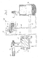
- Fig. 1 is schematically a compressor unit 31 with a compressor 12 and a connected thereto arrangement for controlling the cooling fluid flow 30.
- the compressor 12 is driven by a drive shaft 32 from a (not shown) Drive powered.
- a cooling fluid in present case oil supplied.
- the present in the form of oil cooling fluid is the Lubrication, improves the seal and cools the sucked and compressed Process fluid, which is present here in the form of compressed air.
- the compressed air / oil mixture is supplied via a cooling fluid / process fluid line 37 to a fluid separator 38.
- the Fluid separator 38 is the cooling fluid / process fluid mixture, here as an oil / compressed air mixture present, separated.
- the recovered in the form of compressed air process fluid is to an output line 39 and from there via consumer lines (not shown) supplied to one or more consumers.
- the recovered in the fluid separator 38, in the form of oil cooling fluid passes via a return line 40 to a first node 41, at which a radiator line 21 to a fluid cooler 14 and from there to a second node 42nd leads.
- a bypass line 20 connects the first node 41 and the second one Junction 42 directly under bridging the fluid cooler 14th
- the second node 42 in the present embodiment is in a valve unit 43 defined.
- the valve unit 43 may preferably be directly on the compressor block or be attached to the fluid separator 38 or on the fluid cooler 14.
- the valve unit 43 includes a system control actuator 15 provided with a fluid thermocouple 29 is in operative connection and a fluid control means 19 based on Temperature of the cooling fluid controls (see Fig. 2).
- a system control actuator 15 provided with a fluid thermocouple 29 is in operative connection and a fluid control means 19 based on Temperature of the cooling fluid controls (see Fig. 2).
- Cooling cooling fluid is the flow of the fluid via the fluid cooler via the fluid control means reduced cooling fluid reduced; At the same time, the partial flow of the over Bypass line 20 on the fluid cooler 14 passed by cooling fluid increases, so that the Cooling fluid is cooled less total.
- the cooling fluid can, as shown in the present case, still be stirred via an oil filter 44 and is again via the already mentioned supply line 36 in the compression space 35 of the compressor 12 initiated.
- the arrangement according to the invention for control the cooling fluid flow is in one above the compression space 35 of the compressor 12th and the fluid separator 38 integrated circuit leading.
- a cooling fluid inlet 11 of Arrangement for controlling the cooling fluid flow 30 is present by the already mentioned return line 40 and a cooling fluid outlet 13 through which also already mentioned supply line 36 defined.
- FIG. 2 a first embodiment of Fig. 1 is only schematically illustrated Valve unit 43 in a specific embodiment in a sectional view shown.
- the valve unit 43 initially comprises a but valve block 45 with a central bore 46, a first lateral bore 47, a second lateral bore 48 and a third lateral bore 49.
- the central bore 46 has a upper portion 50, a middle portion 51 and a lower portion 52.
- the lower portion 52 defines a central valve interior 53.
- the middle Section is extended over the lower portion 52 and the upper portion 50 and forms a valve chamber 54.
- the valve chamber 54 is above the first lateral Bore 47 in fluid communication with the supply line 36 to the compression space 35 of the compressor 12.
- the central valve interior 53 is above the second side bore 48 in fluid communication with the bypass conduit 20.
- the upper portion 50 of the central bore 46 in the valve block 45 defines an upper valve interior 55, via the third lateral bore 49 with the fluid cooler 14 in fluid communication stands.
- the central bore 46 of the valve block 45 is a - here in one piece from a Control 24 and an already mentioned fluid control means 19 existing - control cylinder 25 recorded longitudinally displaceable.
- the trained at its lower end Fluid control means is provided to either pass over the fluid cooler 14 Partial flow, or to block the guided over the bypass line 20 partial flow or set a specific mixing ratio between these two streams.
- the formed as a fluid control means 19 part of the control cylinder 25 a first circumferential sealing surface 56.
- the control cylinder at its opposite lying on the upper end of a second circumferential sealing surface 57.
- the circulating Sealing surfaces 56 and 57 are formed and sized to be fluid tight seal against the wall of the central bore 46.
- the second one prevents this circumferential sealing surface 57 the escape of oil.
- the first circumferential sealing surface 56 causes in contrast in a first or second end position of the control cylinder 25 a, except for a leakage current, complete shut-off of either the guided over the fluid cooler 14 Partial flow or the guided over the bypass line 20 partial flow.
- the displacement of the control cylinder 25 between said end positions or also in intermediate positions happens as follows. First, the control cylinder 25 by a arranged in the central valve interior 53 coil spring 58 under bias in an upper, here the guided over the fluid cooler 14 partial flow shut-off Position pressed. A displacement of the control cylinder 25 from this end position can now either via a system control actuator 15 or a summer / winter operation actuator 16 done.
- the system control actuator 15 is mounted, which is activated by the fluid thermocouple. Upon heating of the fluid thermocouple 29 a cloth placed in it expands and pushes the System control actuator 15 out of the fluid thermocouple 29 out.
- the system control actuator 15 is supported via an adjusting piston 27 against a relative to the valve block 45 fixed abutment surface 26 from, so that upon expansion of the fluid in the thermocouple 29 housed fabric of the control cylinder 25 total against the pressure the coil spring 58 is moved in the direction of the central valve interior 53 and such an upper annular gap 59 between the upper valve interior 55 and the valve chamber 54 releases.
- the control cylinder 25 also by the already mentioned summer / winter operation actuator 16 are moved as follows.
- An outside air thermocouple 18 is in a valve cover 61 axially to the system control actuator 15, wherein the summer / winter operation actuator 16 to the valve chamber 54 facing the system control actuator 15 within the outside air thermocouple 18 is slidably mounted. Also in the outside air thermocouple is housed under an increase in temperature expansive substance, the expansion pushing out the summer / winter operation actuator 16 causes.
- the Outside air thermocouple 18 is either directly in contact with ambient air or receives an approximately representative of the ambient air temperature exposure.
- Within the valve cover 61 is axial to the summer / winter operation actuator 16 and the system control actuator 15 further a control crown 62 slidably stored.
- the control crown 62 preferably has a plurality of webs 63 which by associated recesses 64 in a central bore 46 of the valve block 45 covering cover plate 65 pass through. About the cover plate 65 is the Valve cover 61 connected to the valve block 45.
- the summer / winter operation actuator 16 gives only one Minimum position for the width of the upper annular gap 59, i. for the amount of over the fluid cooler 14 guided partial flow before.
- the cooling fluid should be like that heat the system control actuator 15 so far from the fluid thermocouple 29th is pressed out that he exerts a force on the contact surface 26, the Control cylinder 25 move further in the direction of the central valve interior 53 and thus further increase the upper annular gap 59.
- the system control actuator 15 is unable to match the width of the summer / winter operation actuator 16 predetermined upper annular gap 59 to reduce.
- Fig. 3 is an alternative embodiment of a valve unit for an arrangement for controlling the cooling fluid flow according to the invention.
- the two embodiments Essentially differ in that the summer / winter operation actuator 16 in the embodiment of Fig. 3 is not an outside air thermocouple 18 is applied, but a manual actuator, in In this case, specifically, a hand lever 17, which comprises an actuating shaft 22 and an integrally formed on the actuating shaft 22 eccentric 23 - for example at a 120 ° twist of the actuating shaft 22 - in a similar manner as the webs 63 of the control crown 62 acts on the control cylinder 25.
- a hand lever 17 which comprises an actuating shaft 22 and an integrally formed on the actuating shaft 22 eccentric 23 - for example at a 120 ° twist of the actuating shaft 22 - in a similar manner as the webs 63 of the control crown 62 acts on the control cylinder 25.
- valve block 45 is carried out in the embodiment of FIG. 3 slightly longer and has a fourth lateral bore 66 which traverses the central bore 46, and on one side of the central bore 46 has a through hole and on the opposite lying side defined a blind hole.
- this fourth lateral bore 66th the actuating shaft 22 is inserted above the control cylinder 25.
- the actuating shaft 22 is held by means of a bearing disc 67 in the bore 66.
- the eccentric 23 on the actuating shaft 22 is defined by two eccentric sections 68, 69, which lie on both sides of a circumferential groove 70.
- the circumferential groove 70 defines in the present embodiment, the contact surface 26 for the adjusting piston 27 of the system control actuator 15 and is characterized in that the position of this Contact surface 22 remains constant upon actuation of the actuating shaft. While the by the circumferential groove 70 defined contact surface 26 in its height position Turning the actuating shaft 22 remains constant, push the eccentric portions 68, 69th the control cylinder 25 in the direction of the central valve interior 43, so that the upper annular gap 59 depending on the dimensions of the eccentricity of the eccentric sections 68, 69 enlarged. In the present embodiment, at a 120 ° twist the actuating shaft 22 of the lower annular gap 60 is closed, so that in the Partial flow guided via the bypass line is blocked. The effect of the system control actuator 15 is also off in this end position.
- FIG. 4 the embodiment of a valve unit of FIG. 3 in a second position shown, in which case the pivoted by 120 ° hand lever 17 is not shown.
- the upper annular gap 59 is fully open, wherein at the same time the lower annular gap 60 is closed by the control element 24.
- the Bearing surface 26 of the eccentric 23 of the actuating shaft 22 presses the control cylinder 25th and thus the control element 24 against the coil spring 58, so that the upper annular gap 59th opened and the lower annular gap 60 is closed.
- the adjusting piston 27 of System horraktuators 15 is no longer based in the illustration shown against the Abutment surface 26 of the actuating shaft 22 from, so that the System Kunststoffaktuator 15 in the shown position exerts no influence on the control 24 more.
- This embodiment applies even if the adjusting piston 27 completely is extended from the fluid thermocouple 29, so that not only for a specific Temperature regime, but independent of the temperature of the cooling fluid Priority circuit is realized.
- a Priority circuit can be realized, in which in certain areas of the cooling fluid temperature the adjusting piston 27 of the system control actuator 15 still has a control effect the control 24 can transmit.
Landscapes
- Engineering & Computer Science (AREA)
- Mechanical Engineering (AREA)
- General Engineering & Computer Science (AREA)
- Applications Or Details Of Rotary Compressors (AREA)
- Compressor (AREA)
- Control Of Positive-Displacement Air Blowers (AREA)
- Control Of Positive-Displacement Pumps (AREA)
- Fluid-Pressure Circuits (AREA)
- Structures Of Non-Positive Displacement Pumps (AREA)
Applications Claiming Priority (2)
| Application Number | Priority Date | Filing Date | Title |
|---|---|---|---|
| DE10153459A DE10153459B9 (de) | 2001-10-30 | 2001-10-30 | Anordnung zur Steuerung des Kühlfluidstroms in Kompressoren |
| DE10153459 | 2001-10-30 |
Publications (3)
| Publication Number | Publication Date |
|---|---|
| EP1308625A2 true EP1308625A2 (fr) | 2003-05-07 |
| EP1308625A3 EP1308625A3 (fr) | 2003-09-03 |
| EP1308625B1 EP1308625B1 (fr) | 2006-10-11 |
Family
ID=7704169
Family Applications (1)
| Application Number | Title | Priority Date | Filing Date |
|---|---|---|---|
| EP02017501A Expired - Lifetime EP1308625B1 (fr) | 2001-10-30 | 2002-08-06 | Appareillage de commande d'un système de refroidissement pour compresseur |
Country Status (5)
| Country | Link |
|---|---|
| US (1) | US6719546B2 (fr) |
| EP (1) | EP1308625B1 (fr) |
| AT (1) | ATE342446T1 (fr) |
| CA (1) | CA2406554C (fr) |
| DE (2) | DE10153459B9 (fr) |
Cited By (2)
| Publication number | Priority date | Publication date | Assignee | Title |
|---|---|---|---|---|
| EP2484911A2 (fr) | 2011-02-08 | 2012-08-08 | Gardner Denver Oy | Procédé et appareil pour le réglage de la température de fonctionnement de compresseur d'air |
| EP2458219A3 (fr) * | 2010-11-30 | 2012-10-17 | Gustav Wahler GmbH u. Co.KG | Dispositif de commande du flux d'agent réfrigérant dans des compresseurs |
Families Citing this family (8)
| Publication number | Priority date | Publication date | Assignee | Title |
|---|---|---|---|---|
| DE20015744U1 (de) * | 2000-09-12 | 2001-01-25 | Werner Rietschle GmbH + Co. KG, 79650 Schopfheim | Pumpe mit Wassereinspeisung |
| BE1014297A3 (nl) * | 2001-07-13 | 2003-08-05 | Atlas Copco Airpower Nv | Watergeinjecteerde schroefcompressor. |
| DE60229284D1 (de) * | 2001-12-07 | 2008-11-20 | Compair Uk Ltd | Öleingespritzter verdichter |
| US9518579B2 (en) | 2010-01-22 | 2016-12-13 | Ingersoll-Rand Company | Oil flooded compressor having motor operated temperature controlled mixing valve |
| US9500191B2 (en) | 2010-01-22 | 2016-11-22 | Ingersoll-Rand Company | Compressor system including a flow and temperature control device |
| DE102011118438B4 (de) | 2011-11-12 | 2024-02-08 | Zf Cv Systems Hannover Gmbh | Kühlvorrichtung zum Kühlen von Druckluft |
| BE1020500A3 (nl) * | 2012-02-29 | 2013-11-05 | Atlas Copco Airpower Nv | Compressorinrichting en werkwijze voor het aansturen van een compressorinrichting. |
| CN113074112A (zh) * | 2019-12-17 | 2021-07-06 | 河南美力达汽车有限公司 | 一种用于新能源汽车的空压机 |
Family Cites Families (9)
| Publication number | Priority date | Publication date | Assignee | Title |
|---|---|---|---|---|
| SE427493B (sv) * | 1978-07-11 | 1983-04-11 | Atlas Copco Ab | Regleranordning vid vetskeinsprutad kompressor |
| DD141862B1 (de) * | 1979-01-03 | 1981-02-25 | Joachim Mohr | Optisches system fuer spektralgeraete |
| JPS5612093A (en) * | 1979-07-10 | 1981-02-05 | Tokico Ltd | Oil cooled compressor |
| DE3122361A1 (de) * | 1981-06-05 | 1982-12-23 | Bauer Schraubenverdichter GmbH, 8190 Wolfratshausen | Ventilblock fuer das steuern der oelzufuhr eines schraubenverdichters |
| US4431390A (en) * | 1981-10-23 | 1984-02-14 | Dresser Industries, Inc. | Condensation control apparatus for oil-flooded compressors |
| DE3601816A1 (de) * | 1986-01-22 | 1987-07-23 | Pressluft Frantz Gmbh | Luftgekuehlter, insbesondere fahrbarer kompressor |
| IT209903Z2 (it) * | 1987-02-02 | 1988-11-04 | Enea Mattei Spa | Gruppo valvola termostatica e filtro olio, per compressori. |
| DE9105021U1 (de) * | 1990-11-17 | 1991-06-20 | Gustav Wahler Gmbh U. Co, 7300 Esslingen | Thermostatventil zur Regelung der Temperatur der Kühlflüssigkeit einer Brennkraftmaschine |
| US5318151A (en) * | 1993-03-17 | 1994-06-07 | Ingersoll-Rand Company | Method and apparatus for regulating a compressor lubrication system |
-
2001
- 2001-10-30 DE DE10153459A patent/DE10153459B9/de not_active Expired - Fee Related
-
2002
- 2002-08-06 AT AT02017501T patent/ATE342446T1/de not_active IP Right Cessation
- 2002-08-06 EP EP02017501A patent/EP1308625B1/fr not_active Expired - Lifetime
- 2002-08-06 DE DE50208397T patent/DE50208397D1/de not_active Expired - Lifetime
- 2002-10-04 CA CA002406554A patent/CA2406554C/fr not_active Expired - Lifetime
- 2002-10-29 US US10/283,795 patent/US6719546B2/en not_active Expired - Lifetime
Cited By (2)
| Publication number | Priority date | Publication date | Assignee | Title |
|---|---|---|---|---|
| EP2458219A3 (fr) * | 2010-11-30 | 2012-10-17 | Gustav Wahler GmbH u. Co.KG | Dispositif de commande du flux d'agent réfrigérant dans des compresseurs |
| EP2484911A2 (fr) | 2011-02-08 | 2012-08-08 | Gardner Denver Oy | Procédé et appareil pour le réglage de la température de fonctionnement de compresseur d'air |
Also Published As
| Publication number | Publication date |
|---|---|
| EP1308625A3 (fr) | 2003-09-03 |
| CA2406554A1 (fr) | 2003-04-30 |
| US20030082065A1 (en) | 2003-05-01 |
| DE50208397D1 (de) | 2006-11-23 |
| ATE342446T1 (de) | 2006-11-15 |
| DE10153459C2 (de) | 2003-12-04 |
| US6719546B2 (en) | 2004-04-13 |
| DE10153459B9 (de) | 2004-09-09 |
| DE10153459A1 (de) | 2003-05-15 |
| CA2406554C (fr) | 2009-05-26 |
| EP1308625B1 (fr) | 2006-10-11 |
Similar Documents
| Publication | Publication Date | Title |
|---|---|---|
| DE60304555T2 (de) | Verfahren zur steuerung der ölrückführung in einem öleingespritzten schraubenverdichter und verdichter nach diesem verfahren | |
| DE102010050605B4 (de) | Vorrichtung zur Regelung eines Kühlmittelstroms sowie Kühlsystem | |
| EP2054691A1 (fr) | Soupape de dérivation pour refroidisseur raccordé en aval d'une machine hydraulique | |
| EP1308625B1 (fr) | Appareillage de commande d'un système de refroidissement pour compresseur | |
| DE3617132A1 (de) | Schneckenkompressor mit zwillingsschieber | |
| DE3617133A1 (de) | Steuerung fuer einen kompressor mit zwillingsschiebern | |
| DE3300129A1 (de) | Druckluftbetaetigtes werkzeug mit einem stillstands- bzw. abwuerg-drehkraftregler und mit einer luftvorspaneinrichtung | |
| DE102006052296A1 (de) | Thermostatisches Ventil zur Regelung eines Massenstromes | |
| DE102004010997B3 (de) | Expansionsventil und Verfahren zu dessen Steuerung | |
| DE102004020589A1 (de) | Temperaturabhängige Strömungsregelventile für Motorkühlsysteme | |
| DE112014004621T5 (de) | Einhebel-Thermostatkartusche | |
| EP1072796B1 (fr) | Procédé de commande d'un compresseur à vis | |
| DE19713770C2 (de) | Klimaregelung für Kraftfahrzeuge | |
| DE102011079898A1 (de) | Pumpe | |
| EP2792882A2 (fr) | Compresseur d'air pour une installation d'air comprimé, notamment pour une installation de freinage à air comprimé d'un véhicule utilitaire | |
| DE2321487A1 (de) | Steuerungsmechanismus fuer stroemungsmittelgeraete, insbesondere fuer pumpen | |
| DE3719843A1 (de) | Ventil zur regelung der oeltemperatur eines triebwerks | |
| DE102004036301A1 (de) | Kältemaschine und Verfahren zum Betreiben einer Kältemaschine | |
| EP2458219B1 (fr) | Dispositif de commande du flux d'agent réfrigérant dans des compresseurs | |
| DE60309073T2 (de) | Ventil | |
| EP1378710B1 (fr) | Régulateur de pression pour un brûleur à pulvérisation de chauffage de véhicule | |
| DE102006060099A1 (de) | Thermostatisches Expansionsventil | |
| DE69202647T2 (de) | Zwei-Geschwindigkeitshubfahrtsteuereinrichtung für einen hydraulischen Aufzug. | |
| DE102015217236B4 (de) | Thermostatventil für Kühlmittel von Verbrennungsmotoren | |
| DE102004012782B4 (de) | Thermostatventil |
Legal Events
| Date | Code | Title | Description |
|---|---|---|---|
| PUAI | Public reference made under article 153(3) epc to a published international application that has entered the european phase |
Free format text: ORIGINAL CODE: 0009012 |
|
| AK | Designated contracting states |
Designated state(s): AT BE BG CH CY CZ DE DK EE ES FI FR GB GR IE IT LI LU MC NL PT SE SK TR |
|
| AX | Request for extension of the european patent |
Extension state: AL LT LV MK RO SI |
|
| PUAL | Search report despatched |
Free format text: ORIGINAL CODE: 0009013 |
|
| AK | Designated contracting states |
Kind code of ref document: A3 Designated state(s): AT BE BG CH CY CZ DE DK EE ES FI FR GB GR IE IT LI LU MC NL PT SE SK TR |
|
| AX | Request for extension of the european patent |
Extension state: AL LT LV MK RO SI |
|
| 17P | Request for examination filed |
Effective date: 20030822 |
|
| AKX | Designation fees paid |
Designated state(s): AT BE BG CH CY CZ DE DK EE ES FI FR GB GR IE IT LI LU MC NL PT SE SK TR |
|
| 17Q | First examination report despatched |
Effective date: 20050622 |
|
| GRAP | Despatch of communication of intention to grant a patent |
Free format text: ORIGINAL CODE: EPIDOSNIGR1 |
|
| GRAS | Grant fee paid |
Free format text: ORIGINAL CODE: EPIDOSNIGR3 |
|
| GRAA | (expected) grant |
Free format text: ORIGINAL CODE: 0009210 |
|
| AK | Designated contracting states |
Kind code of ref document: B1 Designated state(s): AT BE BG CH CY CZ DE DK EE ES FI FR GB GR IE IT LI LU MC NL PT SE SK TR |
|
| PG25 | Lapsed in a contracting state [announced via postgrant information from national office to epo] |
Ref country code: NL Free format text: LAPSE BECAUSE OF FAILURE TO SUBMIT A TRANSLATION OF THE DESCRIPTION OR TO PAY THE FEE WITHIN THE PRESCRIBED TIME-LIMIT Effective date: 20061011 Ref country code: IT Free format text: LAPSE BECAUSE OF FAILURE TO SUBMIT A TRANSLATION OF THE DESCRIPTION OR TO PAY THE FEE WITHIN THE PRESCRIBED TIME-LIMIT;WARNING: LAPSES OF ITALIAN PATENTS WITH EFFECTIVE DATE BEFORE 2007 MAY HAVE OCCURRED AT ANY TIME BEFORE 2007. THE CORRECT EFFECTIVE DATE MAY BE DIFFERENT FROM THE ONE RECORDED. Effective date: 20061011 Ref country code: IE Free format text: LAPSE BECAUSE OF FAILURE TO SUBMIT A TRANSLATION OF THE DESCRIPTION OR TO PAY THE FEE WITHIN THE PRESCRIBED TIME-LIMIT Effective date: 20061011 Ref country code: SK Free format text: LAPSE BECAUSE OF FAILURE TO SUBMIT A TRANSLATION OF THE DESCRIPTION OR TO PAY THE FEE WITHIN THE PRESCRIBED TIME-LIMIT Effective date: 20061011 Ref country code: FI Free format text: LAPSE BECAUSE OF FAILURE TO SUBMIT A TRANSLATION OF THE DESCRIPTION OR TO PAY THE FEE WITHIN THE PRESCRIBED TIME-LIMIT Effective date: 20061011 Ref country code: CZ Free format text: LAPSE BECAUSE OF FAILURE TO SUBMIT A TRANSLATION OF THE DESCRIPTION OR TO PAY THE FEE WITHIN THE PRESCRIBED TIME-LIMIT Effective date: 20061011 |
|
| REG | Reference to a national code |
Ref country code: GB Ref legal event code: FG4D Free format text: NOT ENGLISH |
|
| REG | Reference to a national code |
Ref country code: CH Ref legal event code: EP |
|
| REG | Reference to a national code |
Ref country code: IE Ref legal event code: FG4D Free format text: LANGUAGE OF EP DOCUMENT: GERMAN |
|
| REF | Corresponds to: |
Ref document number: 50208397 Country of ref document: DE Date of ref document: 20061123 Kind code of ref document: P |
|
| PG25 | Lapsed in a contracting state [announced via postgrant information from national office to epo] |
Ref country code: BG Free format text: LAPSE BECAUSE OF FAILURE TO SUBMIT A TRANSLATION OF THE DESCRIPTION OR TO PAY THE FEE WITHIN THE PRESCRIBED TIME-LIMIT Effective date: 20070111 Ref country code: DK Free format text: LAPSE BECAUSE OF FAILURE TO SUBMIT A TRANSLATION OF THE DESCRIPTION OR TO PAY THE FEE WITHIN THE PRESCRIBED TIME-LIMIT Effective date: 20070111 |
|
| PG25 | Lapsed in a contracting state [announced via postgrant information from national office to epo] |
Ref country code: ES Free format text: LAPSE BECAUSE OF FAILURE TO SUBMIT A TRANSLATION OF THE DESCRIPTION OR TO PAY THE FEE WITHIN THE PRESCRIBED TIME-LIMIT Effective date: 20070122 |
|
| GBT | Gb: translation of ep patent filed (gb section 77(6)(a)/1977) |
Effective date: 20070103 |
|
| REG | Reference to a national code |
Ref country code: SE Ref legal event code: TRGR |
|
| PG25 | Lapsed in a contracting state [announced via postgrant information from national office to epo] |
Ref country code: PT Free format text: LAPSE BECAUSE OF FAILURE TO SUBMIT A TRANSLATION OF THE DESCRIPTION OR TO PAY THE FEE WITHIN THE PRESCRIBED TIME-LIMIT Effective date: 20070319 |
|
| NLV1 | Nl: lapsed or annulled due to failure to fulfill the requirements of art. 29p and 29m of the patents act | ||
| ET | Fr: translation filed | ||
| REG | Reference to a national code |
Ref country code: IE Ref legal event code: FD4D |
|
| PLBE | No opposition filed within time limit |
Free format text: ORIGINAL CODE: 0009261 |
|
| STAA | Information on the status of an ep patent application or granted ep patent |
Free format text: STATUS: NO OPPOSITION FILED WITHIN TIME LIMIT |
|
| 26N | No opposition filed |
Effective date: 20070712 |
|
| REG | Reference to a national code |
Ref country code: CH Ref legal event code: PL |
|
| PG25 | Lapsed in a contracting state [announced via postgrant information from national office to epo] |
Ref country code: MC Free format text: LAPSE BECAUSE OF NON-PAYMENT OF DUE FEES Effective date: 20070831 Ref country code: CH Free format text: LAPSE BECAUSE OF NON-PAYMENT OF DUE FEES Effective date: 20070831 Ref country code: LI Free format text: LAPSE BECAUSE OF NON-PAYMENT OF DUE FEES Effective date: 20070831 Ref country code: GR Free format text: LAPSE BECAUSE OF FAILURE TO SUBMIT A TRANSLATION OF THE DESCRIPTION OR TO PAY THE FEE WITHIN THE PRESCRIBED TIME-LIMIT Effective date: 20070112 |
|
| PG25 | Lapsed in a contracting state [announced via postgrant information from national office to epo] |
Ref country code: EE Free format text: LAPSE BECAUSE OF FAILURE TO SUBMIT A TRANSLATION OF THE DESCRIPTION OR TO PAY THE FEE WITHIN THE PRESCRIBED TIME-LIMIT Effective date: 20061011 |
|
| PG25 | Lapsed in a contracting state [announced via postgrant information from national office to epo] |
Ref country code: AT Free format text: LAPSE BECAUSE OF NON-PAYMENT OF DUE FEES Effective date: 20070806 |
|
| PG25 | Lapsed in a contracting state [announced via postgrant information from national office to epo] |
Ref country code: LU Free format text: LAPSE BECAUSE OF NON-PAYMENT OF DUE FEES Effective date: 20070806 Ref country code: CY Free format text: LAPSE BECAUSE OF FAILURE TO SUBMIT A TRANSLATION OF THE DESCRIPTION OR TO PAY THE FEE WITHIN THE PRESCRIBED TIME-LIMIT Effective date: 20061011 |
|
| PG25 | Lapsed in a contracting state [announced via postgrant information from national office to epo] |
Ref country code: TR Free format text: LAPSE BECAUSE OF FAILURE TO SUBMIT A TRANSLATION OF THE DESCRIPTION OR TO PAY THE FEE WITHIN THE PRESCRIBED TIME-LIMIT Effective date: 20061011 |
|
| REG | Reference to a national code |
Ref country code: DE Ref legal event code: R082 Ref document number: 50208397 Country of ref document: DE Representative=s name: MEISSNER, BOLTE & PARTNER GBR, DE |
|
| REG | Reference to a national code |
Ref country code: DE Ref legal event code: R081 Ref document number: 50208397 Country of ref document: DE Owner name: KAESER KOMPRESSOREN AG, DE Free format text: FORMER OWNER: KAESER KOMPRESSOREN GMBH, 96450 COBURG, DE Effective date: 20130409 Ref country code: DE Ref legal event code: R082 Ref document number: 50208397 Country of ref document: DE Representative=s name: MEISSNER, BOLTE & PARTNER GBR, DE Effective date: 20130409 Ref country code: DE Ref legal event code: R081 Ref document number: 50208397 Country of ref document: DE Owner name: KAESER KORNPRESSOREN SE, DE Free format text: FORMER OWNER: KAESER KOMPRESSOREN GMBH, 96450 COBURG, DE Effective date: 20130409 Ref country code: DE Ref legal event code: R081 Ref document number: 50208397 Country of ref document: DE Owner name: KAESER KOMPRESSOREN SE, DE Free format text: FORMER OWNER: KAESER KOMPRESSOREN GMBH, 96450 COBURG, DE Effective date: 20130409 Ref country code: DE Ref legal event code: R082 Ref document number: 50208397 Country of ref document: DE Representative=s name: MEISSNER BOLTE PATENTANWAELTE RECHTSANWAELTE P, DE Effective date: 20130409 |
|
| REG | Reference to a national code |
Ref country code: GB Ref legal event code: 732E Free format text: REGISTERED BETWEEN 20131107 AND 20131113 |
|
| REG | Reference to a national code |
Ref country code: FR Ref legal event code: CJ Effective date: 20140227 |
|
| REG | Reference to a national code |
Ref country code: DE Ref legal event code: R082 Ref document number: 50208397 Country of ref document: DE Representative=s name: MEISSNER, BOLTE & PARTNER GBR, DE |
|
| REG | Reference to a national code |
Ref country code: DE Ref legal event code: R081 Ref document number: 50208397 Country of ref document: DE Owner name: KAESER KORNPRESSOREN SE, DE Free format text: FORMER OWNER: KAESER KOMPRESSOREN AG, 96450 COBURG, DE Effective date: 20140513 Ref country code: DE Ref legal event code: R082 Ref document number: 50208397 Country of ref document: DE Representative=s name: MEISSNER, BOLTE & PARTNER GBR, DE Effective date: 20140513 Ref country code: DE Ref legal event code: R081 Ref document number: 50208397 Country of ref document: DE Owner name: KAESER KOMPRESSOREN SE, DE Free format text: FORMER OWNER: KAESER KOMPRESSOREN AG, 96450 COBURG, DE Effective date: 20140513 Ref country code: DE Ref legal event code: R082 Ref document number: 50208397 Country of ref document: DE Representative=s name: MEISSNER BOLTE PATENTANWAELTE RECHTSANWAELTE P, DE Effective date: 20140513 |
|
| REG | Reference to a national code |
Ref country code: DE Ref legal event code: R082 Ref document number: 50208397 Country of ref document: DE Representative=s name: MEISSNER, BOLTE & PARTNER GBR, DE |
|
| REG | Reference to a national code |
Ref country code: DE Ref legal event code: R082 Ref document number: 50208397 Country of ref document: DE Representative=s name: MEISSNER, BOLTE & PARTNER GBR, DE Effective date: 20140827 Ref country code: DE Ref legal event code: R081 Ref document number: 50208397 Country of ref document: DE Owner name: KAESER KOMPRESSOREN SE, DE Free format text: FORMER OWNER: KAESER KORNPRESSOREN SE, 96450 COBURG, DE Effective date: 20140827 Ref country code: DE Ref legal event code: R082 Ref document number: 50208397 Country of ref document: DE Representative=s name: MEISSNER BOLTE PATENTANWAELTE RECHTSANWAELTE P, DE Effective date: 20140827 |
|
| REG | Reference to a national code |
Ref country code: FR Ref legal event code: PLFP Year of fee payment: 15 |
|
| REG | Reference to a national code |
Ref country code: FR Ref legal event code: PLFP Year of fee payment: 16 |
|
| REG | Reference to a national code |
Ref country code: FR Ref legal event code: PLFP Year of fee payment: 17 |
|
| PGFP | Annual fee paid to national office [announced via postgrant information from national office to epo] |
Ref country code: IT Payment date: 20210820 Year of fee payment: 20 Ref country code: FR Payment date: 20210830 Year of fee payment: 20 |
|
| PGFP | Annual fee paid to national office [announced via postgrant information from national office to epo] |
Ref country code: GB Payment date: 20210826 Year of fee payment: 20 Ref country code: SE Payment date: 20210823 Year of fee payment: 20 Ref country code: BE Payment date: 20210826 Year of fee payment: 20 Ref country code: DE Payment date: 20210830 Year of fee payment: 20 |
|
| REG | Reference to a national code |
Ref country code: DE Ref legal event code: R071 Ref document number: 50208397 Country of ref document: DE |
|
| REG | Reference to a national code |
Ref country code: GB Ref legal event code: PE20 Expiry date: 20220805 |
|
| REG | Reference to a national code |
Ref country code: BE Ref legal event code: MK Effective date: 20220806 |
|
| REG | Reference to a national code |
Ref country code: SE Ref legal event code: EUG |
|
| PG25 | Lapsed in a contracting state [announced via postgrant information from national office to epo] |
Ref country code: GB Free format text: LAPSE BECAUSE OF EXPIRATION OF PROTECTION Effective date: 20220805 |