EP1308624A1 - Tauchmotorpumpe - Google Patents
Tauchmotorpumpe Download PDFInfo
- Publication number
- EP1308624A1 EP1308624A1 EP01125851A EP01125851A EP1308624A1 EP 1308624 A1 EP1308624 A1 EP 1308624A1 EP 01125851 A EP01125851 A EP 01125851A EP 01125851 A EP01125851 A EP 01125851A EP 1308624 A1 EP1308624 A1 EP 1308624A1
- Authority
- EP
- European Patent Office
- Prior art keywords
- stator
- protective tube
- pump
- eccentric screw
- housing
- Prior art date
- Legal status (The legal status is an assumption and is not a legal conclusion. Google has not performed a legal analysis and makes no representation as to the accuracy of the status listed.)
- Granted
Links
- 230000001681 protective effect Effects 0.000 claims abstract description 66
- 229920001971 elastomer Polymers 0.000 claims description 21
- 239000000806 elastomer Substances 0.000 claims description 20
- 238000007789 sealing Methods 0.000 description 3
- 229910000831 Steel Inorganic materials 0.000 description 2
- 238000012423 maintenance Methods 0.000 description 2
- 239000010959 steel Substances 0.000 description 2
- 238000005452 bending Methods 0.000 description 1
- 238000010276 construction Methods 0.000 description 1
- 238000003780 insertion Methods 0.000 description 1
- 230000037431 insertion Effects 0.000 description 1
- 238000009434 installation Methods 0.000 description 1
- 238000004519 manufacturing process Methods 0.000 description 1
- 239000000463 material Substances 0.000 description 1
- 230000002250 progressing effect Effects 0.000 description 1
- 230000001737 promoting effect Effects 0.000 description 1
Images
Classifications
-
- F—MECHANICAL ENGINEERING; LIGHTING; HEATING; WEAPONS; BLASTING
- F04—POSITIVE - DISPLACEMENT MACHINES FOR LIQUIDS; PUMPS FOR LIQUIDS OR ELASTIC FLUIDS
- F04C—ROTARY-PISTON, OR OSCILLATING-PISTON, POSITIVE-DISPLACEMENT MACHINES FOR LIQUIDS; ROTARY-PISTON, OR OSCILLATING-PISTON, POSITIVE-DISPLACEMENT PUMPS
- F04C2/00—Rotary-piston machines or pumps
- F04C2/08—Rotary-piston machines or pumps of intermeshing-engagement type, i.e. with engagement of co-operating members similar to that of toothed gearing
- F04C2/10—Rotary-piston machines or pumps of intermeshing-engagement type, i.e. with engagement of co-operating members similar to that of toothed gearing of internal-axis type with the outer member having more teeth or tooth-equivalents, e.g. rollers, than the inner member
- F04C2/107—Rotary-piston machines or pumps of intermeshing-engagement type, i.e. with engagement of co-operating members similar to that of toothed gearing of internal-axis type with the outer member having more teeth or tooth-equivalents, e.g. rollers, than the inner member with helical teeth
-
- F—MECHANICAL ENGINEERING; LIGHTING; HEATING; WEAPONS; BLASTING
- F04—POSITIVE - DISPLACEMENT MACHINES FOR LIQUIDS; PUMPS FOR LIQUIDS OR ELASTIC FLUIDS
- F04C—ROTARY-PISTON, OR OSCILLATING-PISTON, POSITIVE-DISPLACEMENT MACHINES FOR LIQUIDS; ROTARY-PISTON, OR OSCILLATING-PISTON, POSITIVE-DISPLACEMENT PUMPS
- F04C13/00—Adaptations of machines or pumps for special use, e.g. for extremely high pressures
- F04C13/008—Pumps for submersible use, i.e. down-hole pumping
Definitions
- the invention relates to a submersible pump with a motor and a Eccentric screw pump, which are connected to each other via a drive shaft are connected.
- Submersible pumps are known, in which on a motor housing an eccentric screw pump is attached. Because of it eccentric The eccentric screw pump rotor must run this and the motor is connected to one another via a flexible shaft or a cardan shaft get connected. This shaft is usually arranged in a protective tube. A pump head is also required to connect a pressure line to the To be able to connect the pump. The eccentric screw pump is usually between the pump head and the protective tube via additional Tension rods tensioned. Furthermore, the eccentric screw pump must be on the stator a flange may be formed around the pump with a pipeline or to connect a pump head. The stator of the pump must therefore absorb additional pipeline forces, which is a more complex construction and more stable dimensioning of the stator is required.
- the submersible motor pump according to the invention has an eccentric screw pump on which is driven by a motor via a drive shaft becomes.
- the eccentric screw pump also known as the Moineau pump, has an external stator and one inside arranged rotor.
- the stator has a longitudinal bore with a constant, circular cross section, the eccentric one The center rotates helically around the longitudinal axis.
- the stator length with one turn is called a step.
- the rotor also has a circular cross-section of equal length along its entire length, the The center is also helically eccentric around the longitudinal axis rotates.
- the rotor has twice the number of turns as the stator.
- the drive shaft and the eccentric screw pump arranged in a common protective tube.
- this common protective tube has a constant cross section so that a smooth outer jacket of the submersible pump is created can be.
- the protective tube is connected to the motor housing of the Motors connected.
- the protective tube can have a larger diameter or Have cross-section as the eccentric screw pump. This makes possible a simple attachment of a pump head to the protective tube without that additional fasteners are required.
- the rotor and stator of the pump can be used as a cartridge can be formed, which easily replaces as a wearing part can be.
- the diameter or cross section of the protective tube is preferably chosen depending on the diameter of a well pipe, in which submersible pump is to be used. A common standard measure for example, is 3 inches in diameter.
- the protective tube is preferably at a first end with the motor housing and connected to a pump head at a second end.
- the protective tube screwed to the motor housing via an external or internal thread and the pump head can also have a corresponding Thread screwed into the protective tube or screwed onto it become.
- the eccentric screw pump is removed by removing the pump head easily accessible so that the stator which one Wear part of the eccentric screw pump is easy to replace can. It is not necessary to exchange a variety of Loosen screws, since preferably only the pump head from the Protective tube must be unscrewed.
- a first support element arranged in the protective tube, which is connected to the protective tube and the stator of the eccentric screw pump at a first longitudinal end of the stator in an axial direction supported and fixed in a radial direction in the protective tube.
- this support element is designed as a flat disc, which itself extends transversely to the longitudinal axis of the protective tube.
- the support element is in Fixed inside the protective tube, for example with the protective tube welded. This first support element is preferably on the engine facing side of the stator.
- a further preference is in the region of a second longitudinal end of the stator second support element arranged, which the stator in the radial direction fixed in the protective tube.
- the stator has a preferably circular cylindrical stator housing and one on the inner wall of the stator housing arranged elastomer layer, the Elastomer layer on at least a first longitudinal end of the stator housing extends beyond its longitudinal end.
- the elastomer layer consists of rubber or a suitable elastomer. In that this layer extends in the longitudinal direction beyond the stator housing, can the elastomer layer, in which the stator structure is formed, simultaneously can be used as a seal for the stator housing. So it is not required to seal the pressure chamber inside the stator on Provide an additional sealing element at the end of the stator housing.
- the Sealing function can at the same time from the anyway in the eccentric screw pump existing elastomer material become.
- the elastomer layer extends at least on the first longitudinal end of the stator housing radially over an inner circumference of the Outward.
- the elastomer layer is thus covered in the radial direction at least a portion of the end face or edge of the stator housing.
- the elastomer layer can thus be used as an axial seal between the stator housing and an adjacent component Act.
- the elastomer layer preferably extends over the entire End face or end edge of the stator housing, which is usually a Steel tube is. In this way, a reliable seal of the Can be reached inside the eccentric screw pump.
- the second longitudinal end of the stator is preferably supported in the axial direction on the pump head.
- the stator is over the Stator housing between the first support element and the pump head pinched or clamped.
- the required clamping force is over transfer the outer protective tube so that no additional Clamping elements are required.
- the one over the front edge of the stator housing radially projecting area of the elastomer layer is preferred arranged in the region of the second longitudinal end of the stator, so that it as Seal acts between the stator housing and the pump head.
- the pressure range of the eccentric screw pump is very high easily sealed. There is no need for additional sealing elements be arranged between the pump head and eccentric screw pump.
- the eccentric screw pump in the protective tube is preferably at the first and / or second longitudinal end of the Stator formed on an outer surface of the stator at least one recess, which with the first or with the second support element in Intervention is.
- This recess is preferably on the outer circumference of the stator housing trained in the form of a paragraph.
- a through hole is provided, into which the stator or the stator housing engages with the return.
- the return forms a paragraph or a shoulder, which in the axial direction on the respective support element is applied.
- the diameter of the through hole in the support elements preferably corresponds essentially to the outside diameter of the stator or the stator housing, so that the stator is as possible is fixed without play in the radial direction in the support elements.
- the stator or the stator housing At least on the first support element, which is arranged firmly in the protective tube is supported, the stator or the stator housing with the recess in axial direction.
- the second support element is preferably also as formed flat disc, which has outer dimensions, which in Essentially correspond to the inner dimensions of the protective tube, see above that the second support element in the radial direction, i.e. transverse to the longitudinal direction of the support tube, is fixed in this.
- the eccentric screw pump is preferred along the length of the stator only fixed in the axial direction by the pump head.
- the second Support element is loosely arranged so that it can be used to replace the stator housing can be easily removed from the protective tube.
- the protective tube the motor housing and preferably the pump head in cross section essentially the same external dimensions.
- one Submersible pump created which is a substantially constant Has cross-section so that it can be easily inserted into a borehole can be removed again without the risk that the pump got caught in the well.
- a smooth appearance of the Pump can be created, which is easy to use and clean the pump favors.
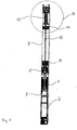
- Figure 1 shows a cross-sectional view of the entire submersible pump.
- the submersible pump is usually in the vertical direction Drilled hole inserted so that the outflow end is arranged at the top. In the Further description will be of this orientation of the submersible pump assumed, this does not exclude another arrangement.
- the motor 2 is located with the associated control electronics at the bottom of the submersible pump and plunges into it promoting medium.
- the electrical connection line is replaced by a Cable duct 4 on the outside of the submersible pump led upwards.
- the Motor 2 with the associated electronics is in a cylindrical motor housing arranged. At the upper end is on the motor housing 5 Thrust bearing 6 screwed on.
- the motor housing 5 and the thrust bearing 6 have essentially the same diameter.
- the thrust bearing 6 simply in the motor housing 5 via appropriate Thread screwed in or screwed in. Closes at the thrust bearing 6 a protective tube 8, which continues in the longitudinal direction of the Motor housing 5 extends upwards. Inside the protective tube 8 is a flexible shaft 10 is arranged, which the thrust bearing 6 with a Eccentric screw pump 12 connects. The thrust bearing 6 is with the Drive shaft of motor 2 in connection. In this way the eccentric screw pump 12 via the thrust bearing 6 and the flexible shaft 10 driven. Instead of a flexible shaft 10, for example a cardan shaft or another gear element is used, which is able to increase the eccentric movement of the pump rotor compensate. Inlet openings 14 are formed in the protective tube, through which the medium to be pumped into the interior of the protective tube 8 flows. Following the flexible shaft 10 is 8 in the protective tube also the eccentric screw pump 12 is arranged.
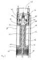
- the eccentric screw pump 12 consists of the rotor 16 and a stator housing 18, in the interior of which an elastomer layer 20 is arranged.
- the stator housing 18 is essentially one circular cylindrical steel tube formed.
- the elastomer layer 20 is on the Inner wall of the stator housing 18 is formed, preferably on this on vulcanized.
- the spiral structure of the stator is in the elastomer layer 20 the eccentric screw pump 12 is formed.
- a first support plate 22 is arranged at the longitudinal end of the eccentric screw pump facing the motor 2 12, d. H. usually the lower longitudinal end, is in the protective tube 8 .
- the support plate 22 is fixed with connected to the protective tube 8, preferably welded.
- a through hole 24 is provided in the support plate 22.
- the stator housing 18 engages with a shoulder 26 at its first longitudinal end in the through hole 24 a.
- the paragraph 26 and thus the stator housing 18 preferably without play in the through hole 24 in the radial direction fixed.
- the shoulder 26 rests with a shoulder in the axial direction the surface, i.e. the top of the support plate 22. In this way the stator housing 18 on the support plate 22 in an axial direction supported.
- the end of the eccentric pump 12 which is in the through hole 24 of the support plate 22 is arranged, forms the entry end, through which a medium to be pumped into the eccentric screw pump 12 occurs.
- the medium to be pumped flows through the inlet holes 14 in the protective tube 18 and then through the through hole 24 in the support plate 22 into the eccentric screw pump 12.
- the second support plate 28 has the same as the first support plate 22 has an outer diameter which is essentially the inner diameter corresponds to the protective tube 8. In this way, the support plate 28 essentially free of play in the radial direction in the protective tube 8 fixed.
- the support plate 28 has a central through hole 30, through which extends the stator housing 18.
- the through hole 30 is like the through hole 24 concentric with the longitudinal axis of the protective tube 8 arranged.
- the protective tube 18 also has its second Longitudinal end on a shoulder 32, which in the through hole 30 on the Support plate 28 engages.
- the stator housing 18 is as free of play as possible arranged in the through hole 30 in order to radially fix the Stator housing in the protective tube 8 also at the second longitudinal end of the Ensure stator. So that the stator can be easily replaced can, the support plate 28 is not in the protective tube 8 in the axial direction fixed. It lies only on the shoulder of the shoulder 32 of the stator housing 18 on. To remove the stator with the stator housing 18, the Support plate 28 simply pulled up out of the protective tube 8 so that subsequently the stator and rotor of the eccentric screw pump 12 can also be removed from the protective tube 8.
- valve 40 e.g. Check or pressure relief valve, arranged.
- valve 40 is a check valve.
- the pump head 34 also takes over the fixing of the eccentric screw pump 12 in the axial direction in the protective tube 8.
- the elastomer layer is used to seal the pressure side of the eccentric screw pump 12 20 at the second longitudinal end of the stator housing 18 as Collar 44 formed.
- the collar 44 is both axial and radial direction over the stator housing 18 so that it has the front edge of the stator housing 18 covered at least on its inner circumference.
- the collar 44 extends over the entire circumference of the stator housing 18.
- the collar 44 lies between the longitudinal end 42 of the pump head 34 and the stator housing 18 so that it is the interface seals between these two elements. It is therefore not an additional one Seal between stator and pump head 34 required.
- the protective tube 8 allows a pump head in a simple manner 34 can be arranged on the eccentric screw pump 12 which has a larger diameter than the eccentric screw pump 12 having. In particular, this also enables the arrangement of a larger one Valve 40.
- the entire outer jacket of the submersible pump has preferably a substantially constant diameter or cross section on (see Figure 1). This favors easy insertion and Take the submersible pump into a borehole.
- the invention Submersible pump can be made in different diameters depending on the size of the borehole in which they are used shall be. Preferably the diameter is between 3 and 5 inches.
- the head piece 34 which is larger in diameter, enables connection a pressure pipe with a larger pipe diameter.
Landscapes
- Engineering & Computer Science (AREA)
- Mechanical Engineering (AREA)
- General Engineering & Computer Science (AREA)
- Structures Of Non-Positive Displacement Pumps (AREA)
- Rotary Pumps (AREA)
Abstract
Description
- Figur 1
- eine Querschnittansicht einer bevorzugten Ausführungsform der erfindungsgemäßen Tauchmotorpumpe und
- Figur 2
- eine vergrößerte Ansicht des Ausschnitts A aus Figur 1.
- 2 -
- Motor
- 4 -
- Kabelkanal
- 5 -
- Motorgehäuse
- 6 -
- Drucklager
- 8 -
- Schutzrohr
- 10 -
- biegsame Welle
- 12 -
- Exzenterschneckenpumpe
- 14 -
- Eintrittsöffnungen
- 16 -
- Rotor
- 18 -
- Statorgehäuse
- 20 -
- Elastomerschicht
- 22 -
- erste Stützplatte
- 24 -
- Durchgangsloch
- 26 -
- Absatz
- 28 -
- zweite Stützplatte
- 30 -
- Durchgangsloch
- 32 -
- Absatz
- 34 -
- Kopfstück bzw. Pumpenkopf
- 36 -
- Gewinde
- 38 -
- Austrittsöffnung
- 40 -
- Ventil
- 42 -
- Längsende
- 44 -
- Kragen
Claims (9)
- Tauchmotorpumpe mit einem Motor (2) und einer Exzenterschneckenpumpe (12), welche über eine Antriebswelle (10) miteinander verbunden sind, dadurch gekennzeichnet, dass die Antriebswelle (10) und die Exzenterschneckenpumpe (12) in einem gemeinsamen Schutzrohr (8) angeordnet sind, welches mit einem den Motor (2) umgebenden Motorgehäuse (5) verbunden ist.
- Tauchmotorpumpe nach Anspruch 1, bei welcher das Schutzrohr (8) an einem ersten Ende mit dem Motorgehäuse (5) und an einem zweiten Ende mit einem Pumpenkopf (34) verbunden ist.
- Tauchmotorpumpe nach einem der vorangehenden Ansprüche, bei welcher in dem Schutzrohr (8) ein erstes Stützelement (22) angeordnet ist, welches mit dem Schutzrohr (8) verbunden ist und den Stator der Exzenterschneckenpumpe (12) an einem ersten Längsende des Stators in einer axialen Richtung abstützt und in radialer Richtung in dem Schutzrohr (8) fixiert.
- Tauchmotorpumpe nach Anspruch 3, bei welcher im Bereich eines zweiten Längsendes des Stators ein zweites Stützelement (28) angeordnet ist, welches den Stator in radialer Richtung in dem Schutzrohr (8) fixiert.
- Tauchmotorpumpe nach einem der vorangehenden Ansprüche, bei welcher der Stator ein vorzugsweise kreiszylindrisches Statorgehäuse (18) und eine an der Innenwandung des Statorgehäuses (18) angeordnete Elastomerschicht (20) aufweist, wobei die Elastomerschicht (20) sich an zumindest einem ersten Längsende des Statorgehäuses (18) über dessen Längsende hinauserstreckt.
- Tauchmotorpumpe nach Anspruch 5, bei welcher sich die Elastomerschicht(20) zumindest an dem ersten Längsende des Statorgehäuses (18) radial über einen Innenumfang des Statorgehäuses (18) hinaus nach außen erstreckt.
- Tauchmotorpumpe nach einem der Ansprüche 3 bis 6, bei welcher sich das zweite Längsende des Stators in axialer Richtung an dem Pumpenkopf (34) abstützt.
- Tauchmotorpumpe nach einem der Ansprüche 3 bis 7, bei welcher an dem ersten und/oder zweiten Längsende des Stators an einer Außenfläche des Stators zumindest ein Rücksprung (26,32) ausgebildet ist, welcher mit dem ersten (22) bzw. zweiten (28) Stützelement in Eingriff ist.
- Tauchmotorpumpe nach einem der vorangehenden Ansprüche, bei welchem das Schutzrohr (8), das Motorgehäuse (5) und vorzugsweise der Pumpenkopf (34) im Querschnitt im wesentlichen gleiche Außenmaße aufweisen.
Priority Applications (2)
| Application Number | Priority Date | Filing Date | Title |
|---|---|---|---|
| EP20010125851 EP1308624B1 (de) | 2001-10-30 | 2001-10-30 | Tauchmotorpumpe |
| DE50108332T DE50108332D1 (de) | 2001-10-30 | 2001-10-30 | Tauchmotorpumpe |
Applications Claiming Priority (1)
| Application Number | Priority Date | Filing Date | Title |
|---|---|---|---|
| EP20010125851 EP1308624B1 (de) | 2001-10-30 | 2001-10-30 | Tauchmotorpumpe |
Publications (2)
| Publication Number | Publication Date |
|---|---|
| EP1308624A1 true EP1308624A1 (de) | 2003-05-07 |
| EP1308624B1 EP1308624B1 (de) | 2005-12-07 |
Family
ID=8179114
Family Applications (1)
| Application Number | Title | Priority Date | Filing Date |
|---|---|---|---|
| EP20010125851 Expired - Lifetime EP1308624B1 (de) | 2001-10-30 | 2001-10-30 | Tauchmotorpumpe |
Country Status (2)
| Country | Link |
|---|---|
| EP (1) | EP1308624B1 (de) |
| DE (1) | DE50108332D1 (de) |
Cited By (4)
| Publication number | Priority date | Publication date | Assignee | Title |
|---|---|---|---|---|
| WO2008105007A1 (en) * | 2007-03-01 | 2008-09-04 | Hero Europe S.R.L. | Cartridge -type single-screw pump and dye-meter equipped with such pump |
| CN110873046A (zh) * | 2019-12-24 | 2020-03-10 | 李辉 | 一种过油管投捞式电潜螺杆泵 |
| CN115874987A (zh) * | 2021-09-29 | 2023-03-31 | 中国石油天然气股份有限公司 | 小直径可投捞式电动潜油螺杆泵采油装置及采油方法 |
| CN116806290A (zh) * | 2020-12-04 | 2023-09-26 | 维世科泵业和计量技术有限公司 | 转子单元和单螺杆泵 |
Families Citing this family (2)
| Publication number | Priority date | Publication date | Assignee | Title |
|---|---|---|---|---|
| CN105464630A (zh) * | 2016-01-04 | 2016-04-06 | 山东润发石油设备科技有限公司 | 大扭矩潜油电机直驱螺杆泵 |
| EP3825552B1 (de) | 2019-11-22 | 2025-03-12 | Grundfos Holding A/S | Exzenterschneckenpumpe |
Citations (8)
| Publication number | Priority date | Publication date | Assignee | Title |
|---|---|---|---|---|
| US3802803A (en) * | 1971-10-13 | 1974-04-09 | A Bogdanov | Submersible screw pump |
| FR2372333A1 (fr) * | 1976-11-24 | 1978-06-23 | Mecanique Metallurgie Ste Gle | Perfectionnements aux pompes a vis |
| US4718824A (en) * | 1983-09-12 | 1988-01-12 | Institut Francais Du Petrole | Usable device, in particular for the pumping of an extremely viscous fluid and/or containing a sizeable proportion of gas, particularly for petrol production |
| DE3820003A1 (de) * | 1988-06-11 | 1989-12-21 | Grundfos Int | Tauchpumpenaggregat |
| DE9319138U1 (de) * | 1993-12-08 | 1994-05-19 | Meyer, Werner, 59889 Eslohe | Druckerhöhungsgerät für flüssige bis zähflüssige Beförderungsstoffe mit einstellbarem Druckausgleichsmantel |
| DE19615171C1 (de) * | 1996-04-17 | 1997-11-27 | Guenther Boehler Gmbh | Pumpe zur Entnahme von Flüssigkeitsproben |
| DE19827101A1 (de) * | 1998-06-18 | 1999-12-23 | Artemis Kautschuk Kunststoff | Nach dem Moineau-Prinzip arbeitende Maschine für den Einsatz in Tiefbohrungen |
| US6089832A (en) * | 1998-11-24 | 2000-07-18 | Atlantic Richfield Company | Through-tubing, retrievable downhole pump system |
-
2001
- 2001-10-30 DE DE50108332T patent/DE50108332D1/de not_active Expired - Lifetime
- 2001-10-30 EP EP20010125851 patent/EP1308624B1/de not_active Expired - Lifetime
Patent Citations (8)
| Publication number | Priority date | Publication date | Assignee | Title |
|---|---|---|---|---|
| US3802803A (en) * | 1971-10-13 | 1974-04-09 | A Bogdanov | Submersible screw pump |
| FR2372333A1 (fr) * | 1976-11-24 | 1978-06-23 | Mecanique Metallurgie Ste Gle | Perfectionnements aux pompes a vis |
| US4718824A (en) * | 1983-09-12 | 1988-01-12 | Institut Francais Du Petrole | Usable device, in particular for the pumping of an extremely viscous fluid and/or containing a sizeable proportion of gas, particularly for petrol production |
| DE3820003A1 (de) * | 1988-06-11 | 1989-12-21 | Grundfos Int | Tauchpumpenaggregat |
| DE9319138U1 (de) * | 1993-12-08 | 1994-05-19 | Meyer, Werner, 59889 Eslohe | Druckerhöhungsgerät für flüssige bis zähflüssige Beförderungsstoffe mit einstellbarem Druckausgleichsmantel |
| DE19615171C1 (de) * | 1996-04-17 | 1997-11-27 | Guenther Boehler Gmbh | Pumpe zur Entnahme von Flüssigkeitsproben |
| DE19827101A1 (de) * | 1998-06-18 | 1999-12-23 | Artemis Kautschuk Kunststoff | Nach dem Moineau-Prinzip arbeitende Maschine für den Einsatz in Tiefbohrungen |
| US6089832A (en) * | 1998-11-24 | 2000-07-18 | Atlantic Richfield Company | Through-tubing, retrievable downhole pump system |
Cited By (7)
| Publication number | Priority date | Publication date | Assignee | Title |
|---|---|---|---|---|
| WO2008105007A1 (en) * | 2007-03-01 | 2008-09-04 | Hero Europe S.R.L. | Cartridge -type single-screw pump and dye-meter equipped with such pump |
| CN101965457A (zh) * | 2007-03-01 | 2011-02-02 | 欧洲英雄(股份)责任有限公司 | 一种芯式单螺杆泵及使用该泵的染料仪 |
| US8556134B2 (en) | 2007-03-01 | 2013-10-15 | Hero Europe S.R.L. | Cartridge-type single-screw pump and dye-meter equipped with such pump |
| CN101965457B (zh) * | 2007-03-01 | 2014-03-19 | 欧洲英雄(股份)责任有限公司 | 一种芯式单螺杆泵及使用该泵的染料仪 |
| CN110873046A (zh) * | 2019-12-24 | 2020-03-10 | 李辉 | 一种过油管投捞式电潜螺杆泵 |
| CN116806290A (zh) * | 2020-12-04 | 2023-09-26 | 维世科泵业和计量技术有限公司 | 转子单元和单螺杆泵 |
| CN115874987A (zh) * | 2021-09-29 | 2023-03-31 | 中国石油天然气股份有限公司 | 小直径可投捞式电动潜油螺杆泵采油装置及采油方法 |
Also Published As
| Publication number | Publication date |
|---|---|
| EP1308624B1 (de) | 2005-12-07 |
| DE50108332D1 (de) | 2006-01-12 |
Similar Documents
| Publication | Publication Date | Title |
|---|---|---|
| DE69308430T2 (de) | Zentrifuge mit Rotorantriebsachse mit einer elastischen Dämpferverbindung | |
| DE3050514C2 (de) | Mehrstufige Wellendichtung | |
| DE102017210770B4 (de) | Schraubenspindelpumpe, Kraftstoffförderaggregat und Kraftstofffördereinheit | |
| EP0664400A1 (de) | Magnetpumpe | |
| DE2750801C2 (de) | Pumpe, insbesondere Faßpumpe | |
| EP1733147B1 (de) | Stator für eine exzenterschneckenpumpe oder einen exzenterschneckenmotor nach dem moineau-prinzip | |
| DE3800336C2 (de) | ||
| DE102012005949A1 (de) | Zweispindelige Schraubenspindelpumpe in zweiflutiger Bauweise | |
| EP2964957B1 (de) | Exzenterschneckenpumpe mit überdruckschutz | |
| DE102004038477B3 (de) | Exzenterschneckenpumpe | |
| EP1308624B1 (de) | Tauchmotorpumpe | |
| EP2721301B1 (de) | Tauchpumpe und verfahren zum zusammenbau einer tauchpumpe | |
| DE69527605T2 (de) | Lageranordnung zur Verwendung in einer Pumpe | |
| EP1233215A2 (de) | Einbaufertige Gleitringdichtung für die Welle einer Pumpe | |
| DE19905435B4 (de) | Tauchpumpe | |
| DE69825815T2 (de) | Peristaltischer Pumpenkopf | |
| DE102019005366A1 (de) | Exzenterschneckenpumpe | |
| EP1795754B1 (de) | Universalflansch | |
| WO2022022773A1 (de) | Verdrehgesicherter rotorspannverbund einer strömungsmaschine | |
| DE102021113724A1 (de) | Schraubenspindelpumpe in einflutiger Bauweise | |
| EP0882891B1 (de) | Exzenterschneckenpumpe | |
| DE102021110892B3 (de) | Elektromotorisch angetriebener hydraulischer Pumpenaktor | |
| DE202008011078U1 (de) | Doppeltbewegliche Kuppelstange | |
| DE102024003042A1 (de) | Pumpenvorrichtung | |
| DE3540192C2 (de) |
Legal Events
| Date | Code | Title | Description |
|---|---|---|---|
| PUAI | Public reference made under article 153(3) epc to a published international application that has entered the european phase |
Free format text: ORIGINAL CODE: 0009012 |
|
| AK | Designated contracting states |
Designated state(s): AT BE CH CY DE DK ES FI FR GB GR IE IT LI LU MC NL PT SE TR |
|
| AX | Request for extension of the european patent |
Extension state: AL LT LV MK RO SI |
|
| 17P | Request for examination filed |
Effective date: 20030607 |
|
| 17Q | First examination report despatched |
Effective date: 20030730 |
|
| TPAC | Observations filed by third parties |
Free format text: ORIGINAL CODE: EPIDOSNTIPA |
|
| AKX | Designation fees paid |
Designated state(s): DE FR GB IT |
|
| GRAP | Despatch of communication of intention to grant a patent |
Free format text: ORIGINAL CODE: EPIDOSNIGR1 |
|
| GRAS | Grant fee paid |
Free format text: ORIGINAL CODE: EPIDOSNIGR3 |
|
| GRAA | (expected) grant |
Free format text: ORIGINAL CODE: 0009210 |
|
| AK | Designated contracting states |
Kind code of ref document: B1 Designated state(s): DE FR GB IT |
|
| PG25 | Lapsed in a contracting state [announced via postgrant information from national office to epo] |
Ref country code: IT Free format text: LAPSE BECAUSE OF FAILURE TO SUBMIT A TRANSLATION OF THE DESCRIPTION OR TO PAY THE FEE WITHIN THE PRESCRIBED TIME-LIMIT;WARNING: LAPSES OF ITALIAN PATENTS WITH EFFECTIVE DATE BEFORE 2007 MAY HAVE OCCURRED AT ANY TIME BEFORE 2007. THE CORRECT EFFECTIVE DATE MAY BE DIFFERENT FROM THE ONE RECORDED. Effective date: 20051207 |
|
| REG | Reference to a national code |
Ref country code: GB Ref legal event code: FG4D Free format text: NOT ENGLISH |
|
| REF | Corresponds to: |
Ref document number: 50108332 Country of ref document: DE Date of ref document: 20060112 Kind code of ref document: P |
|
| GBT | Gb: translation of ep patent filed (gb section 77(6)(a)/1977) |
Effective date: 20060222 |
|
| ET | Fr: translation filed | ||
| PLBE | No opposition filed within time limit |
Free format text: ORIGINAL CODE: 0009261 |
|
| STAA | Information on the status of an ep patent application or granted ep patent |
Free format text: STATUS: NO OPPOSITION FILED WITHIN TIME LIMIT |
|
| 26N | No opposition filed |
Effective date: 20060908 |
|
| REG | Reference to a national code |
Ref country code: FR Ref legal event code: PLFP Year of fee payment: 16 |
|
| REG | Reference to a national code |
Ref country code: FR Ref legal event code: PLFP Year of fee payment: 17 |
|
| REG | Reference to a national code |
Ref country code: FR Ref legal event code: PLFP Year of fee payment: 18 |
|
| PGFP | Annual fee paid to national office [announced via postgrant information from national office to epo] |
Ref country code: IT Payment date: 20201030 Year of fee payment: 20 Ref country code: GB Payment date: 20201022 Year of fee payment: 20 Ref country code: FR Payment date: 20201020 Year of fee payment: 20 Ref country code: DE Payment date: 20201026 Year of fee payment: 20 |
|
| REG | Reference to a national code |
Ref country code: DE Ref legal event code: R071 Ref document number: 50108332 Country of ref document: DE |
|
| REG | Reference to a national code |
Ref country code: GB Ref legal event code: PE20 Expiry date: 20211029 |
|
| PG25 | Lapsed in a contracting state [announced via postgrant information from national office to epo] |
Ref country code: GB Free format text: LAPSE BECAUSE OF EXPIRATION OF PROTECTION Effective date: 20211029 |