EP1308333A1 - Ablegbares Fahrzeugdach für ein Cabriolet - Google Patents
Ablegbares Fahrzeugdach für ein Cabriolet Download PDFInfo
- Publication number
- EP1308333A1 EP1308333A1 EP02022842A EP02022842A EP1308333A1 EP 1308333 A1 EP1308333 A1 EP 1308333A1 EP 02022842 A EP02022842 A EP 02022842A EP 02022842 A EP02022842 A EP 02022842A EP 1308333 A1 EP1308333 A1 EP 1308333A1
- Authority
- EP
- European Patent Office
- Prior art keywords
- roof
- roof part
- vehicle
- link
- lever
- Prior art date
- Legal status (The legal status is an assumption and is not a legal conclusion. Google has not performed a legal analysis and makes no representation as to the accuracy of the status listed.)
- Granted
Links
- 230000008878 coupling Effects 0.000 description 8
- 238000010168 coupling process Methods 0.000 description 8
- 238000005859 coupling reaction Methods 0.000 description 8
- 238000003466 welding Methods 0.000 description 4
- 230000000977 initiatory effect Effects 0.000 description 2
- 230000005540 biological transmission Effects 0.000 description 1
- 238000006073 displacement reaction Methods 0.000 description 1
- 210000003746 feather Anatomy 0.000 description 1
- 239000000463 material Substances 0.000 description 1
- 239000013641 positive control Substances 0.000 description 1
- 230000000007 visual effect Effects 0.000 description 1
Images





Classifications
-
- B—PERFORMING OPERATIONS; TRANSPORTING
- B60—VEHICLES IN GENERAL
- B60J—WINDOWS, WINDSCREENS, NON-FIXED ROOFS, DOORS, OR SIMILAR DEVICES FOR VEHICLES; REMOVABLE EXTERNAL PROTECTIVE COVERINGS SPECIALLY ADAPTED FOR VEHICLES
- B60J7/00—Non-fixed roofs; Roofs with movable panels, e.g. rotary sunroofs
- B60J7/08—Non-fixed roofs; Roofs with movable panels, e.g. rotary sunroofs of non-sliding type, i.e. movable or removable roofs or panels, e.g. let-down tops or roofs capable of being easily detached or of assuming a collapsed or inoperative position
- B60J7/12—Non-fixed roofs; Roofs with movable panels, e.g. rotary sunroofs of non-sliding type, i.e. movable or removable roofs or panels, e.g. let-down tops or roofs capable of being easily detached or of assuming a collapsed or inoperative position foldable; Tensioning mechanisms therefor, e.g. struts
- B60J7/14—Non-fixed roofs; Roofs with movable panels, e.g. rotary sunroofs of non-sliding type, i.e. movable or removable roofs or panels, e.g. let-down tops or roofs capable of being easily detached or of assuming a collapsed or inoperative position foldable; Tensioning mechanisms therefor, e.g. struts with a plurality of rigid plate-like elements or rigid non plate-like elements, e.g. with non-slidable, but pivotable or foldable movement
- B60J7/143—Non-fixed roofs; Roofs with movable panels, e.g. rotary sunroofs of non-sliding type, i.e. movable or removable roofs or panels, e.g. let-down tops or roofs capable of being easily detached or of assuming a collapsed or inoperative position foldable; Tensioning mechanisms therefor, e.g. struts with a plurality of rigid plate-like elements or rigid non plate-like elements, e.g. with non-slidable, but pivotable or foldable movement for covering the passenger compartment
- B60J7/146—Non-fixed roofs; Roofs with movable panels, e.g. rotary sunroofs of non-sliding type, i.e. movable or removable roofs or panels, e.g. let-down tops or roofs capable of being easily detached or of assuming a collapsed or inoperative position foldable; Tensioning mechanisms therefor, e.g. struts with a plurality of rigid plate-like elements or rigid non plate-like elements, e.g. with non-slidable, but pivotable or foldable movement for covering the passenger compartment all elements being folded in same orientation and stacked fashion
Definitions
- the invention relates to a vehicle roof with at least one front first Roof part and an adjoining second roof part, which between the Vehicle interior covering closed position and a vehicle interior releasing storage position in a rear roof storage space are adjustable, the front roof part being arranged laterally by means of one each Multi-joint device movably mounted on the second roof part and at Stowing over the second roof part can be raised.
- a vehicle roof is known from DE 199 62 070 A1, in which the front roof part by means of a four-bar joint on the middle roof part of a three-part Roof is pivotally hinged.
- the two handlebars of the four-bar linkage are on a protruding far beyond the middle roof part Support arm pivoted in joints that are close together.
- the linkage is arranged on the support arm far in front of the middle roof part, so that with handlebars swinging back the front roof part not with the middle one Collide roof part.
- the disadvantage is that due to the close proximity Joints only a comparatively low stability of the front bearing Roof part is possible.
- DE 199 34 673 C1 describes a vehicle roof with three movable roof parts become known in which the central roof part by means of a main four-bar linkage is mounted on the vehicle, the front roof part by means of a four-bar linkage on middle roof part is stored and the rear roof part on the rear main link attached to the main four-bar linkage and pivotable with it.
- the roof parts are stored one above the other in the trunk of the vehicle so that the rear Roof part with its underside facing upwards, while the front one is above Roof part is placed in the same bombed position over the middle roof part, so that the tops face up. They are also with this vehicle roof Swivel bearing of the two handlebars of the front four-bar linkage close together a support arm protruding forward from the central roof section with corresponding Disadvantages arranged for stability.
- the invention has for its object a vehicle roof mentioned to create an improved storage of the first roof part on the second Has roof part and an improved swivel drive of the storage.
- the object is achieved according to the invention in the above vehicle roof solved that a rear link of the multi-joint device on the second Roof part around a swivel axis set back from its front edge is pivotally mounted and when laying the roof out of the roof surface of the swings out the second roof section. Thanks to the recessed swivel axis there will be a larger distance between the bearings of the rear handlebar and a front link of the multi-joint device on the second roof part achieved without the storage of the front handlebar on a support arm must be arranged very far in front of the roof surface of the second roof part, whereby again the disadvantage eliminated by the invention would occur that the second roof part would be excessively extended by this support arm.
- the rear link is preferably flush with the roof in the closed position Roof surface of the second roof part or arranged below the roof surface.
- the Handlebars can also be integrated into a corresponding increase in the roof area be arranged. In any case, it emerges without any lateral movement Roof surface upwards.
- the depression is, for example, a longitudinal channel between one Roof center part and a roof side part.
- the rear handlebar is at least partially in the pivoted open position is lowered into the rear portion of the recess. So that the first roof part can be lowered directly onto the second roof section.
- the Aperture can be pressed down into the recess by the swiveling handlebar become.
- a front link of the multi-joint device by means of a pivot bearing is pivotally mounted on a protruding forward on the second roof part
- Support arm is arranged in front of the roof surface of the second roof part, and that the front handlebar is driven by a lever mechanism.
- the lever gear allows even with a large swivel angle of the front handlebar Initiation of the driving force, so that dead center positions in the two end positions the pivoting movement can be avoided and also in the vicinity of the End positions a larger lever arm is available to apply force.
- the lever mechanism is preferably with a main pivot drive for storage of the roof positively coupled, so that no separate additional drive is provided must become. On the other hand, it can also have its own drive, so that the movement of the lever gear can be controlled independently can.
- the front link driven by a drive rod and an intermediate lever gear is the one on the second roof part pivotable about a fixed pivot axis Hinged lever in such an arrangement that a larger drive lever arm with constant or reduced drive movement of the drive rod is provided.
- the front handlebar driven by a drive rod and an intermediate lever gear is the one on the second roof part pivotable about a fixed pivot axis Has articulation lever on which the drive rod is articulated, the fixed pivot axis of the link lever is arranged such that at least in one of the two end positions of the pivoting movement of the front handlebar on the drive rod lateral distance of the swivel axis from the pivot point the drive rod on the linkage lever is larger than the lateral distance the pivot of the front handlebar from the pivot point of the drive rod on Feedback lever.
- Roof parts can also be used with three or more roof parts.
- the second or middle roof part is pivoted on the body via a multi-joint device and the third or rear roof part is on the multi-joint device second or middle roof part or its body-side storage pivoted.
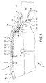
- a vehicle roof 1 of a convertible 2, not shown, is to be opened Hardtop with a front roof part 3, a middle roof part 4 and designed a rear roof part 5 (see Fig. 1).
- the Cabriolet 2 can have a row of seats 1 have a front and a rear row of seats 6 and 7, so that the lengths of the individual roof parts 3, 4, 5 to the respective length of the vehicle interior are adapted.
- the three roof parts 3, 4, 5 are over bearings shown in the figures pivotally mounted, which are provided on both sides of the roof parts.
- the middle roof part 4 is by means of a main link 12 and a main column 13 having main four-joint pivoted in such a way on the body stored that it is in the top compartment 10 with its top facing up is filed.
- the front roof part 3 is by means of a four-bar link that has a front Includes handlebar 14 and a rear handlebar 15 on the central roof part 4 pivoted and swings with the same curvature when put down, d. H.
- the rear Roof part 5 or rear element, the z. B. contains a rear window is by means of a front lever 16 and a rear lever 17 in a four-bar arrangement a bearing arm 18 pivotally mounted on the middle roof part 4 and protrudes beyond the rear end.
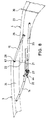
- the front link 14 of the front four-bar bearing the front roof part 3 is by means of a lever mechanism 20 at the front end of a support arm 21 pivotally mounted (see in particular Fig. 8), which is attached to the central roof part 4 and is forward over the front edge 22 of the roof shell 23 of the middle roof part 4 extends in such an arrangement that it in The closed position is covered by the side area 24 of the front roof part 3.
- a front drive or coupling rod 25 for pivoting the front Handlebar 14 is by means of a rear joint 26 on the main link 12 and by means of of a front joint 27 articulated on the lever mechanism 20.
- the front end of the rear link 15 is at the rear end by means of a joint 28 67 of the front roof part 3 hinged.
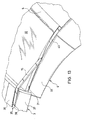
- the rear end of the rear link 15 is pivotally mounted by means of a joint 29 which on middle roof part 4 approximately in the middle between the front edge 22 and the rear edge 30 of the roof shell 23 arranged and opposite the surface of the roof shell 23 is lowered so that the rear link 15 in the closed position of the roof 1 in a recess 31 in the manner of a longitudinal groove or a longitudinal channel is recorded, which is between the central portion 32 and the side portion 33 (see FIG. 13) of the central roof part 4 extends over its length.
- the depression 31 is, for example, a so-called welding trench, in which the both bent down and adjacent side edges of the middle section 32 or the side portion 33 z. B. by welding together are connected.
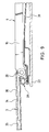
- the front joint 28 of the rear link 15 is on an elongated bearing part 34 attached (Fig. 9), which, for example, also from a welding trench formed recess 35 between the central portion 36 and the side portion 37 of the front roof part 3 (Fig. 13) and attached to it is.
- a diaphragm 38 or cover covers the recess 35 with that received bearing part 34 flush with the surface of the front roof part 3rd from.
- the welding trench or the depression 31 on the central roof part 4 forms one Wet area, which is attached to the front edge 22 of the central roof part 4 Seal 39 is limited to the front. In the closed position of the roof 1 the seal 39 lies tightly against the underside of the front roof part 3.
- An aperture 40 covers the rear portion of the recess 31 between the hinge 29 at the rear end of the rear link 15 and the rear edge 30 the roof shell 23.
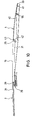
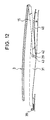
- the aperture 40 is about a rear axis of rotation 41 pivoted and by a biasing device, such as a Spring 66, biased upwards into its covering position, in which it is towards the top the roof shell 23 is arranged flush and with its lowered front end 42 bears from below on a nose 43 at the rear end of the rear link 15. If the rear link 15 is pivoted backwards about the joint 29, the nose 43 depresses the front end 42 of the panel 40 (FIGS. 11 and 12), so that the rear pivoting rear link 15 in the recess 31st can lower and press the aperture 40 down. When closing the roof 1, the rear link 15 lifts out of the recess 31 and its nose 43 guides the aperture 40 into its cover position.
- the rear link 15 is designed such that it is in the closed position of the roof 1st in its arrangement flush with the roof surface, it covers the recess 31 optically, so that a cover for the front portion of the recess 31 is not is required.
- the panel 40 can alternatively be designed at the rear end of the depression 31 of the central roof part 4 be firmly attached and z. B. made of plastic be formed with a certain flexibility so that it bends flexibly, if at their front end 42 and by supporting the handlebar 15th is pushed down. The restoring force is provided by the plastic material.
- the lever mechanism 20 arranged at the front end of the support arm 21 contains, for example, a right-angled angle lever 46 with a first leg 47, the end at the front end of the support arm 21 is pivotally mounted in a joint 48 which is above the front Handlebar 14 bearing joint 44 is arranged.
- the coupling rod 25 is articulated in the joint 27, the is arranged set back from the end of the second leg 49.
- a short connecting lever by means of a joint 50 51 articulated, which on the other hand by means of a joint 52 with the Joint 44 protruding end of the front link 14 pivotally connected is.
- the distance between the joint 27 and the joint 48 in to the coupling rod 25 vertical direction forms the effective swivel arm for the initiation of Driving force on the lever mechanism 20 and thus on the front link 14. Due to the design of the compact lever gear 20 shown the effective swivel arm always large enough so that even with large Swivel angle of the front link 14 both in the closed position and in Open position of the roof 1, the coupling rod 25 from a dead center position to Lever gear 20 or the joint 48 is sufficiently far away.
- the drive for moving the rear roof part 5 contains a rear drive rod 53, which is on the one hand on the on the main link 12 attached joint 26 and on the other hand articulated on a joint 54 which is located adjacent to the hinge 55 which is the rear lever 17 of the four-bar linkage on the bearing arm 18 which supports the rear roof part 5 pivotally mounted.
- a rear drive rod 53 which is on the one hand on the on the main link 12 attached joint 26 and on the other hand articulated on a joint 54 which is located adjacent to the hinge 55 which is the rear lever 17 of the four-bar linkage on the bearing arm 18 which supports the rear roof part 5 pivotally mounted.
- the pivot drive of the main four-bar linkage around the body-fixed links 59 and 60 of the main link 12 or the main column 13 is carried out, for. B. by means of a hydraulically operated piston-cylinder unit 61, for example on the Main column 13 attacks.
- the coupling rod 25 is not connected to the joint 26, but with its own drive device, which has a control device is controlled for a coordinated filing movement.
- FIG. 18 and 19 Another alternative design provides (see Figs. 18 and 19) that the front Coupling rod 25 and the rear drive rod 53 in the joints 26 and 26 'are connected to one another, but these joints 26 and 26' are not attached to the Main link 12 is attached, but on a pivot lever 62, which means a hinge 64 is mounted on the central roof part 4. On this swivel lever 62 engages a drive device 65 so that the movements of the front Roof part 3 and the rear roof part 5 run coupled, but by the control of the drive device regardless of the movement of the Main four-bar linkage or the central roof part 4 are adjustable.
- the rear shelf 19 as a fixed Be formed with the top compartment lid 11, since the top compartment lid 11 is only opened when the rear roof part 5 over the middle Roof part 4 has been pivoted and thus the rear edge 57 of the rear Roof part 5 easily moved past the front edge 63 of the rear shelf 19 can be.
- the rear handlebar in the four-bar bearing of the front roof part 3 15 on the projecting section of the support arm 21 in front of the roof surface 23 of the middle Roof part 4 mounted so that the particular bent or cranked formed rear link 15 according to the arrangement as it is from DE 199 62 070 A1 or DE 199 34 673 C1 is known, in front of and above the roof surface 23 of the central roof part 4 is pivoted and a recess described 31 is not required.
- the drive device or the drive devices can be formed in accordance with the above statements his.
- multi-joint devices can also be used instead of the four-joint bearings shown can be used with more than four joints.
Landscapes
- Engineering & Computer Science (AREA)
- Mechanical Engineering (AREA)
- Body Structure For Vehicles (AREA)
- Seal Device For Vehicle (AREA)
Abstract
Description
- Fig. 1
- in einer Seitenansicht in schematischer Teildarstellung ein Cabriolet mit einem Hardtop-Fahrzeugdach mit einem vorderen, einem mittleren und einem hinteren Dachteil in geschlossener Stellung;
- Fig. 2 bis 7
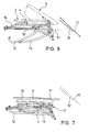
- in einer jeweiligen Seitenansicht in schematischer Darstellung die drei Dachteile beim Ablegen des Hardtop-Fahrzeugdaches in unterschiedlichen Stellungen;
- Fig. 8
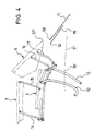
- in einer Seitenansicht in vergrößerter Darstellung das vordere Dachteil beim Hochschwenken über das mittlere Dachteil;
- Fig. 9
- in einer Seitenansicht in schematischer Teildarstellung eine Lenkerverbindung eines Viergelenks zwischen dem vorderen Dachteil und dem mittleren Dachteil;
- Fig. 10 bis 12
- in jeweiligen schematischen Seitenansichten den hinteren Lenker des Viergelenks beim Verschwenken des vorderen Dachteils auf das hintere Dachteil;
- Fig. 13
- in einer perspektivischen Draufsicht auf das Dach das vordere Dachteil beim Hochschwenken über das mittlere Dachteil;
- Fig. 14
- in einer vergrößerten Ausschnittsdarstellung aus Fig. 3 ein Hebelgetriebe für den vorderen Lenker des vorderen Viergelenks;
- Fig. 15
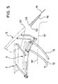
- in einer perspektivischen Draufsicht in schematischer Darstellung das Hebelgetriebe mit den benachbarten Dachteilen;
- Fig. 16
- in einer Seitenansicht in gegenüber Fig. 1 vergrößerter Darstellung das hinter Dachteil in Schließstellung;
- Fig. 17
- in einer Seitenansicht in vergrößerter Darstellung entsprechend Fig. 5 die Lagerung des mittleren und des hinteren Dachteils;
- Fig. 18
- in einer Seitenansicht in schematischer Teildarstellung ein weiteres Ausführungsbeispiel eines Hardtop-Fahrzeugdaches mit einem vorderen, einem mittleren und einem hinteren Dachteil in geschlossener Stellung; und
- Fig. 19
- in einer Seitenansicht in vergrößerter Ausschnittsdarstellung das in Fig. 18 dargestellte Fahrzeug in einer Zwischenöffnungsstellung.
- 1
- Fahrzeugdach
- 2
- Cabriolet
- 3
- vorderes Dachteil
- 4
- mittleres Dachteil
- 5
- hinteres Dachteil
- 6
- vordere Sitzreihe
- 7
- hintere Sitzreihe
- 8
- Windlauf
- 9
- A-Säule
- 10
- Verdeckkasten
- 11
- Verdeckraumklappe
- 12
- Hauptlenker
- 13
- Hauptsäule
- 14
- vorderer Lenker
- 15
- hinterer Lenker
- 16
- vorderer Hebel
- 17
- hinterer Hebel
- 18
- Lagerarm
- 19
- Hutablage
- 20
- Hebelgetriebe
- 21
- Tragarm
- 22
- Vorderrand
- 23
- Dachschale
- 24
- Seitenbereich
- 25
- vordere Koppelstange
- 26
- hinteres Gelenk
- 27
- vorderes Gelenk
- 28
- Gelenk
- 29
- Gelenk
- 30
- Hinterrand
- 31
- Vertiefung
- 32
- Mittelabschnitt
- 33
- Seitenabschnitt
- 34
- Lagerteil
- 35
- Vertiefung
- 36
- Mittelabschnitt
- 37
- Seitenabschnitt
- 38
- Blende
- 39
- Dichtung
- 40
- Blende
- 41
- hintere Drehachse
- 42
- Vorderende
- 43
- Nase
- 44
- hinteres Gelenk
- 45
- vorderes Gelenk
- 46
- Winkelhebel
- 47
- erster Schenkel
- 48
- Gelenk
- 49
- zweiter Schenkel
- 50
- Gelenk
- 51
- Verbindungshebel
- 52
- Gelenk
- 53
- Antriebsstange
- 54
- Gelenk
- 55
- Gelenk
- 56
- Gelenk
- 57
- Hinterrand
- 58
- Vorderrand
- 59
- Gelenk
- 60
- Gelenk
- 61
- Antriebseinrichtung
- 62
- Schwenkhebel
- 63
- Vorderrand
- 64
- Gelenk
- 65
- Antriebseinrichtung
- 66
- Feder
- 67
- Hinterende
Claims (16)
- Fahrzeugdach mit zumindest einem vorderen ersten Dachteil (3) und einem sich anschließenden zweiten Dachteil (4), die zwischen einer den Fahrzeuginnenraum überdeckenden Schließstellung und einer den Fahrzeuginnenraum freigebenden Ablagestellung in einem heckseitigen Dachablageraum (10) verstellbar sind, wobei das vordere Dachteil (3) mittels jeweils einer seitlich angeordneten Mehrgelenkeinrichtung (14, 15) am zweiten Dachteil (4) bewegbar gelagert und beim Ablegen über das zweite (4) Dachteil anhebbar ist,
dadurch gekennzeichnet, daß ein hinterer Lenker (15) der Mehrgelenkeinrichtung (14, 15) am zweiten Dachteil (4) um eine von dessen Vorderrand (22) zurückversetzte Schwenkachse (29) schwenkbar gelagert ist und beim Ablegen des Daches (1) aus der Dachfläche (23) des zweiten Dachteils (4) nach oben ausschwenkt. - Fahrzeugdach nach Anspruch 1,
dadurch gekennzeichnet, daß ein vorderer Lenker (14) der Mehrgelenkeinrichtung (14, 15) in einem Gelenk (44) schwenkbar gelagert ist, das an einem am zweiten Dachteil (4) nach vorne vorstehenden Tragarm (21) vor der Dachfläche (23) des zweiten Dachteils (4) angeordnet ist. - Fahrzeugdach nach Anspruch 1 oder 2,
dadurch gekennzeichnet, daß der hintere Lenker (15) in Schließstellung des Daches (1) bündig zur Dachfläche (23) das zweiten Dachteils (4) oder unterhalb der Dachfläche (23) angeordnet ist. - Fahrzeugdach nach einem der Ansprüche 1 bis 3,
dadurch gekennzeichnet, daß der hintere Lenker (15) in Schließstellung in einer sich nach oben öffnenden Vertiefung (31) im zweiten Dachteil (4) aufgenommen ist. - Fahrzeugdach nach Anspruch 4,
dadurch gekennzeichnet, daß der hintere Lenker (15) in zurückgeschwenkter Offenstellung zumindest teilweise in den Hinterabschnitt der Vertiefung (31) abgesenkt ist. - Fahrzeugdach nach Anspruch 4 oder 5,
dadurch gekennzeichnet, daß die Vertiefung (13) zwischen einem Mittelteil (32) und einem Seitenteil (33) des zweiten Dachteils (4) angeordnet ist. - Fahrzeugdach nach einem der Ansprüche 4 bis 6,
dadurch gekennzeichnet, daß in Schließstellung des Daches (1) eine Blende (40) den Hinterabschnitt der Vertiefung (31) vom hinteren Lenker (15) nach hinten hin abdeckt. - Fahrzeugdach nach Anspruch 7,
dadurch gekennzeichnet, daß die Blende (40) durch den verschwenkenden hinteren Lenker (15) in die Vertiefung (31) herabgedrückt wird. - Fahrzeugdach nach Anspruch 7 oder 8,
dadurch gekennzeichnet, daß die Blende (40) an ihrem Hinterende an dem zweiten Dachteil (4) befestigt ist und an ihrem Vorderende (42) durch einen rückseitigen Vorsprung (43) des verschwenkenden hinteren Lenkers (15) in die Vertiefung (31) herabgedrückt wird. - Fahrzeugdach nach einem der Ansprüche 1 bis 9,
dadurch gekennzeichnet, daß der hintere Lenker (15) am Hinterende (67) des vorderen Dachteils (3) angelenkt ist. - Fahrzeugdach nach einem der Ansprüche 1 bis 10
dadurch gekennzeichnet, daß der vordere Lenker (14) der Mehrgelenkeinrichtung (14, 15) in seiner zurückgeschwenkten Offenstellung in den Vorderabschnitt der Vertiefung (31) abgesenkt ist. - Fahrzeugdach mit zumindest einem vorderen ersten Dachteil (3) und einem sich anschließenden zweiten Dachteil (4), die zwischen einer den Fahrzeuginnenraum überdeckenden Schließstellung und einer den Fahrzeuginnenraum freigebenden Ablagestellung in einem heckseitigen Dachablageraum verstellbar sind, wobei das erste Dachteil (3) mittels jeweils einer seitlich angeordneten Mehrgelenkeinrichtung (14, 15) am zweiten Dachteil (4) bewegbar gelagert und beim Ablegen über das zweite Dachteil (4) anhebbar ist, insbesondere nach einem der Ansprüche 1 bis 11,
dadurch gekennzeichnet, daß ein vorderer Lenker (14) der Mehrgelenkeinrichtung (14, 15) mittels eines Drehlagers (44) schwenkbar gelagert ist, das an einem am zweiten Dachteil (4) nach vorne vorstehenden Tragarm (21) vor der Dachfläche (23) des zweiten Dachteils (4) angeordnet ist, und daß der vordere Lenker (15) über ein Hebelgetriebe (20) angetrieben ist. - Fahrzeugdach nach Anspruch 12,
dadurch gekennzeichnet, daß das Hebelgetriebe (20) mit einem Hauptschwenkantrieb zum Ablegen des Daches zwangsgekoppelt ist oder einen eigenen Antrieb aufweist. - Fahrzeugdach nach Anspruch 12 oder 13,
dadurch gekennzeichnet, daß der vordere Lenker (14) über eine Antriebsstange (25) und ein zwischengeschaltetes Hebelgetriebe (20) angetrieben ist, das einen am zweiten Dachteil (4) um eine fixe Schwenkachse schwenkbaren Anlenkhebel (46) in einer solchen Anordnung aufweist, daß ein größerer Antriebshebelarm bei gleichbleibender oder reduzierter Antriebsbewegung der Antriebsstange (25) bereitgestellt ist. - Fahrzeugdach nach einem der Ansprüche 12 bis 14,
dadurch gekennzeichnet, daß der vordere Lenker (14) über eine Antriebsstange (25) und ein zwischengeschaltetes Hebelgetriebe (20) angetrieben ist, das einen am zweiten Dachteil (4) um eine fixe Schwenkachse (48) schwenkbaren Anlenkhebel (46) aufweist, an dem die Antriebsstange (25) angelenkt ist, wobei die fixe Schwenkachse (48) des Anlenkhebels (46) derart angeordnet ist, daß zumindest in einer der beiden Endlagen der Schwenkbewegung des vorderen Lenkers (14) der bezogen auf die Antriebsstange (25) seitliche Abstand der Schwenkachse (48) vom Anlenkpunkt (27) der Antriebsstange (25) am Anlenkhebel (46) größer ist wie der seitliche Abstand des Drehlagers (44) des vorderen Lenkers (14) vom Anlenkpunkt (27) der Antriebsstange (25) am Anlenkhebel (46). - Fahrzeugdach nach einem der Ansprüche 1 bis 15,
dadurch gekennzeichnet, daß es drei Dachteile (3, 4, 5) aufweist, das zweite oder mittlere Dachteil (4) über eine Mehrgelenkeinrichtung (12, 13) an der Karosserie schwenkbar gelagert ist und das dritte oder hintere Dachteil (5) über eine Mehrgelenkeinrichtung (16, 17) an dem mittleren Dachteil (4) oder dessen karosserieseitiger Lagerung schwenkbar gelagert ist.
Applications Claiming Priority (2)
| Application Number | Priority Date | Filing Date | Title |
|---|---|---|---|
| DE10150219 | 2001-10-12 | ||
| DE10150219A DE10150219A1 (de) | 2001-10-12 | 2001-10-12 | Ablegbares Fahrzeugdach für ein Cabriolet |
Publications (2)
| Publication Number | Publication Date |
|---|---|
| EP1308333A1 true EP1308333A1 (de) | 2003-05-07 |
| EP1308333B1 EP1308333B1 (de) | 2008-11-26 |
Family
ID=7702191
Family Applications (1)
| Application Number | Title | Priority Date | Filing Date |
|---|---|---|---|
| EP02022842A Expired - Lifetime EP1308333B1 (de) | 2001-10-12 | 2002-10-14 | Ablegbares Fahrzeugdach für ein Cabriolet |
Country Status (3)
| Country | Link |
|---|---|
| US (1) | US6767045B2 (de) |
| EP (1) | EP1308333B1 (de) |
| DE (2) | DE10150219A1 (de) |
Cited By (5)
| Publication number | Priority date | Publication date | Assignee | Title |
|---|---|---|---|---|
| DE102005051648B3 (de) * | 2005-10-26 | 2007-05-16 | Magna Car Sys Gmbh | Hardtop-Fahrzeugdach mit mindestens zwei starren Dachteilen |
| DE102005051647B3 (de) * | 2005-10-26 | 2007-05-24 | Magna Car Top Systems Gmbh | Hardtop-Fahrzeugdach mit mindestens zwei starren Dachteilen |
| FR2898302A1 (fr) * | 2006-03-07 | 2007-09-14 | Peugeot Citroen Automobiles Sa | Vehicule a toit escamotable |
| EP1859981A1 (de) * | 2002-04-12 | 2007-11-28 | Edscha Cabrio-Dachsysteme GmbH | Faltverdeck für ein Cabriolet-Fahrzeug |
| EP1897732A3 (de) * | 2006-09-08 | 2010-03-10 | Dr. Ing. h.c. F. Porsche Aktiengesellschaft | Cabriolet |
Families Citing this family (35)
| Publication number | Priority date | Publication date | Assignee | Title |
|---|---|---|---|---|
| FR2814402B1 (fr) * | 2000-09-28 | 2002-11-29 | France Design | Toit escamotable pour vehicule et vehicule notamment du type pick-up equipe d'un tel toit |
| DE10149456A1 (de) * | 2001-10-08 | 2003-04-30 | Cts Fahrzeug Dachsysteme Gmbh | Hardtop-Fahrzeugdach mit mindestens zwei starren Dachteilen |
| DE10152944B4 (de) * | 2001-10-26 | 2016-12-15 | Webasto-Edscha Cabrio GmbH | Verdeck für ein Cabriolet-Fahrzeug |
| DE10205342B4 (de) * | 2002-02-08 | 2004-12-23 | Webasto Vehicle Systems International Gmbh | Cabriolet-Kraftfahrzeug mit klappbarem Hardtop |
| WO2003084773A1 (de) * | 2002-04-09 | 2003-10-16 | Cts Fahrzeug-Dachsysteme Gmbh | Hardtop-fahrzeugdach mit drei starren dachteilen |
| DE10218874B4 (de) * | 2002-04-26 | 2004-06-09 | Cts Fahrzeug-Dachsysteme Gmbh | Hardtop-Fahrzeugdach |
| US7364217B2 (en) * | 2002-09-16 | 2008-04-29 | Edscha Cabrio-Dachsysteme Gmbh | Top for a convertible vehicle |
| US6695386B1 (en) * | 2002-09-18 | 2004-02-24 | Asc Incorporated | Vehicle retractable hardtop roof |
| US6820917B2 (en) * | 2002-09-18 | 2004-11-23 | Asc Incorporated | Vehicle convertible roof |
| FR2846285B1 (fr) * | 2002-10-29 | 2004-12-24 | France Design | Toit retractable pour vehicule automobile |
| DE10258052C5 (de) * | 2002-12-11 | 2008-06-12 | Magna Car Top Systems Gmbh | Verstellbares Fahrzeugdach für Cabriolet-Fahrzeuge |
| US6722724B1 (en) * | 2003-01-29 | 2004-04-20 | Macfarland David P. | Four section retractable hard top |
| DE10316027B4 (de) * | 2003-04-07 | 2005-02-10 | Cts Fahrzeug-Dachsysteme Gmbh | Hardtop-Fahrzeugdach mit drei starren Dachteilen |
| US6964340B2 (en) * | 2003-04-18 | 2005-11-15 | Wilhelm Karmann Gmbh | Retractable hardtop with articulating center panel |
| DE10320171B4 (de) * | 2003-05-05 | 2005-02-24 | Cts Fahrzeug-Dachsysteme Gmbh | Hardtop-Fahrzeugdach mit zwei starren Dachteilen |
| DE10331848B4 (de) * | 2003-07-14 | 2015-01-22 | GM Global Technology Operations LLC (n. d. Ges. d. Staates Delaware) | Kraftfahrzeugkarosserie mit Faltdach |
| DE10351062B3 (de) * | 2003-10-31 | 2005-04-14 | Edscha Cabrio-Dachsysteme Gmbh | Verdeck für ein Cabriolet-Fahrzeug |
| JP2005145303A (ja) * | 2003-11-17 | 2005-06-09 | Kanto Auto Works Ltd | コンバーチブル車 |
| US7063371B2 (en) | 2004-03-12 | 2006-06-20 | Asc Incorporated | Convertible hardtop roof |
| DE102004018905B4 (de) * | 2004-04-15 | 2009-09-24 | Webasto Ag | Klappverdeck eines Fahrzeugs |
| DE102004023056A1 (de) * | 2004-05-11 | 2005-12-01 | Bayerische Motoren Werke Ag | Klappverdeck für ein Kraftfahrzeug |
| DE102004029727B4 (de) * | 2004-06-21 | 2006-09-21 | Webasto Ag | Ablegbares Fahrzeugdach für ein Cabriolet |
| DE102005004018A1 (de) * | 2005-01-28 | 2006-08-03 | Wilhelm Karmann Gmbh | Dachsystem mit wenigstens drei Dachteilen |
| DE102005026827B4 (de) * | 2005-06-09 | 2012-10-11 | Webasto Ag | Fahrzeudach mit einem an einer Mittenführung bewegbar gelagerten Dachteil |
| DE102005043509B4 (de) * | 2005-09-12 | 2007-05-24 | Magna Car Top Systems Gmbh | Dachkonzept für ein Fahrzeug mit offenem Aufbau |
| DE102006002030B3 (de) * | 2006-01-13 | 2007-07-12 | Edscha Cabrio-Dachsysteme Gmbh | Heckscheibenansteuerung |
| JP2007261407A (ja) * | 2006-03-28 | 2007-10-11 | Webasto Japan Kk | リトラクタブルルーフ、及びそれを備えた車両 |
| DE102006028548A1 (de) * | 2006-06-21 | 2007-12-27 | Webasto Ag | Ablegbares Fahrzeugdach |
| DE102006042293A1 (de) * | 2006-09-08 | 2008-03-27 | Dr.Ing.H.C. F. Porsche Ag | Verdeck für ein Cabriolet |
| US8186056B2 (en) * | 2007-06-28 | 2012-05-29 | Siemens Energy, Inc. | Turbine vane restoration system |
| DE102007059574B4 (de) | 2007-12-11 | 2021-10-07 | Magna Car Top Systems Gmbh | Faltverdeck für ein Kraftfahrzeug |
| DE102008032688A1 (de) | 2008-07-02 | 2010-01-07 | Magna Car Top Systems Gmbh | Gelenk |
| DE102009039926B3 (de) * | 2009-09-03 | 2011-03-24 | Webasto-Edscha Cabrio GmbH | Verdeckanordnung für ein Cabriolet-Fahrzeug |
| DE102014217102B4 (de) * | 2014-08-27 | 2020-12-24 | Magna Car Top Systems Gmbh | Mehrteiliges verstellbares Fahrzeugdach |
| DE102015111557B4 (de) | 2015-07-16 | 2017-02-09 | Webasto-Edscha Cabrio GmbH | Cabriolet-Verdeck mit gemeinsam verschwenkbaren Dachlenkern |
Citations (3)
| Publication number | Priority date | Publication date | Assignee | Title |
|---|---|---|---|---|
| DE19934673C1 (de) * | 1999-07-23 | 2001-01-25 | Daimler Chrysler Ag | Hardtop für ein Cabriolet-Fahrzeug |
| WO2001040007A1 (fr) * | 1999-11-30 | 2001-06-07 | France Design | Systeme de toit rigide escamotable pour structure decouvrable, notamment pour vehicule |
| DE10108493A1 (de) * | 2000-02-23 | 2001-09-13 | Edscha Cabrio Dachsys Gmbh | Antriebsvorrichtung für ein Klappverdeck |
Family Cites Families (6)
| Publication number | Priority date | Publication date | Assignee | Title |
|---|---|---|---|---|
| CH403509A (fr) * | 1963-11-18 | 1965-11-30 | Rollman Paul | Toit pour véhicule décapotable |
| JP2631404B2 (ja) * | 1989-05-22 | 1997-07-16 | 関東自動車工業株式会社 | コンバーティブル車の開閉ルーフ |
| DE19926474B4 (de) * | 1999-06-10 | 2010-07-08 | Bayerische Motoren Werke Aktiengesellschaft | Kraftfahrzeug mit einem absenkbaren Verdeckkasten |
| DE19962070C5 (de) * | 1999-12-22 | 2013-05-02 | Webasto-Edscha Cabrio GmbH | Klappdach |
| US6478362B2 (en) * | 1999-12-22 | 2002-11-12 | Ed. Scharwaechter Gmbh | Convertible top and driving device for a convertible top |
| DE10042460B4 (de) * | 2000-08-29 | 2010-06-17 | Webasto Ag | Versenkbares Dach eines Cabriolet-Fahrzeugs |
-
2001
- 2001-10-12 DE DE10150219A patent/DE10150219A1/de not_active Ceased
-
2002
- 2002-10-11 US US10/269,082 patent/US6767045B2/en not_active Expired - Lifetime
- 2002-10-14 EP EP02022842A patent/EP1308333B1/de not_active Expired - Lifetime
- 2002-10-14 DE DE50213050T patent/DE50213050D1/de not_active Expired - Lifetime
Patent Citations (3)
| Publication number | Priority date | Publication date | Assignee | Title |
|---|---|---|---|---|
| DE19934673C1 (de) * | 1999-07-23 | 2001-01-25 | Daimler Chrysler Ag | Hardtop für ein Cabriolet-Fahrzeug |
| WO2001040007A1 (fr) * | 1999-11-30 | 2001-06-07 | France Design | Systeme de toit rigide escamotable pour structure decouvrable, notamment pour vehicule |
| DE10108493A1 (de) * | 2000-02-23 | 2001-09-13 | Edscha Cabrio Dachsys Gmbh | Antriebsvorrichtung für ein Klappverdeck |
Cited By (9)
| Publication number | Priority date | Publication date | Assignee | Title |
|---|---|---|---|---|
| EP1859981A1 (de) * | 2002-04-12 | 2007-11-28 | Edscha Cabrio-Dachsysteme GmbH | Faltverdeck für ein Cabriolet-Fahrzeug |
| US7374226B2 (en) | 2002-04-12 | 2008-05-20 | Edscha Cabrio-Dachsysteme Gmbh | Folding top for a cabriolet vehicle |
| US7896424B2 (en) | 2002-04-12 | 2011-03-01 | Edscha Cabrio-Dachsysteme Gmbh | Folding top for a cabriolet vehicle |
| DE102005051648B3 (de) * | 2005-10-26 | 2007-05-16 | Magna Car Sys Gmbh | Hardtop-Fahrzeugdach mit mindestens zwei starren Dachteilen |
| DE102005051647B3 (de) * | 2005-10-26 | 2007-05-24 | Magna Car Top Systems Gmbh | Hardtop-Fahrzeugdach mit mindestens zwei starren Dachteilen |
| US7500710B2 (en) | 2005-10-26 | 2009-03-10 | Magna Car Top Systems Gmbh | Hardtop vehicle roof with external roof kinematic system |
| EP1780064A3 (de) * | 2005-10-26 | 2009-07-08 | Magna Car Top Systems GmbH | Hardtop-Fahrzeugdach mit außen angeordneter Dachkinematik |
| FR2898302A1 (fr) * | 2006-03-07 | 2007-09-14 | Peugeot Citroen Automobiles Sa | Vehicule a toit escamotable |
| EP1897732A3 (de) * | 2006-09-08 | 2010-03-10 | Dr. Ing. h.c. F. Porsche Aktiengesellschaft | Cabriolet |
Also Published As
| Publication number | Publication date |
|---|---|
| EP1308333B1 (de) | 2008-11-26 |
| DE50213050D1 (de) | 2009-01-08 |
| US6767045B2 (en) | 2004-07-27 |
| US20030085587A1 (en) | 2003-05-08 |
| DE10150219A1 (de) | 2003-04-30 |
Similar Documents
| Publication | Publication Date | Title |
|---|---|---|
| EP1308333B1 (de) | Ablegbares Fahrzeugdach für ein Cabriolet | |
| EP1302351B1 (de) | Ablegbares Fahrzeugdach für ein Cabriolet | |
| EP1112879B1 (de) | Umwandelbares Fahrzeugdach | |
| DE10028405B4 (de) | Kofferraumdeckelanordnung für ein Fahrzeug mit einen einklappbaren Verdeck | |
| EP1839922B1 (de) | Umwandelbares Fahrzeugdach | |
| EP1199202A2 (de) | Cabriolet-Fahrzeug mit einem im rückwärtigen Fahrzeugbereich unterhalb eines Deckelteils ablegbaren Dach | |
| DE10107077B4 (de) | Umwandelbares Fahrzeugdach eines Cabriolets | |
| DE10234351A1 (de) | Cabriolet mit ablegbarem Klappdach | |
| DE10242451B4 (de) | Hutablage eines Cabriolets | |
| EP0927654A2 (de) | Anlenkung für einen Verdeckkastendeckel | |
| DE10132547B4 (de) | Abdeckplatte für das Verdeckgestänge eines Cabrios | |
| DE102004038221B4 (de) | Verdeck für ein Cabriolet-Fahrzeug | |
| EP1601544B1 (de) | Cabriolet-fahrzeug | |
| DE102004023056A1 (de) | Klappverdeck für ein Kraftfahrzeug | |
| EP1897718B1 (de) | Faltverdeck | |
| DE102004029727B4 (de) | Ablegbares Fahrzeugdach für ein Cabriolet | |
| DE10234350A1 (de) | Abdeckvorrichtung für ein ablegbares Dach eines Cabriolets und Cabriolet mit einer derartigen Abdeckvorrichtung | |
| WO2008040310A1 (de) | Abdeckklappe eines cabriolets | |
| DE102005038703B4 (de) | Faltverdeck eines Cabriolet-Fahrzeugs | |
| EP1588884B1 (de) | Klappverdeck eines Fahrzeugs | |
| DE10331987B4 (de) | Verdeckkastendeckel für einen ein verstellbares Fahrzeugdach aufnehmenden Verdeckkasten | |
| WO2007115714A1 (de) | Hardtop-klappverdeck für einen offenen kraftwagen | |
| DE102005045213B4 (de) | Faltverdeck eines Kraftfahrzeugs | |
| DE19714106A1 (de) | Umwandelbares Fahrzeugdach | |
| DE102007054469B4 (de) | Fahrzeugverdeck |
Legal Events
| Date | Code | Title | Description |
|---|---|---|---|
| PUAI | Public reference made under article 153(3) epc to a published international application that has entered the european phase |
Free format text: ORIGINAL CODE: 0009012 |
|
| AK | Designated contracting states |
Designated state(s): AT BE BG CH CY CZ DE DK EE ES FI FR GB GR IE IT LI LU MC NL PT SE SK TR |
|
| AX | Request for extension of the european patent |
Extension state: AL LT LV MK RO SI |
|
| 17P | Request for examination filed |
Effective date: 20031104 |
|
| AKX | Designation fees paid |
Designated state(s): DE FR GB IT |
|
| 17Q | First examination report despatched |
Effective date: 20040929 |
|
| GRAP | Despatch of communication of intention to grant a patent |
Free format text: ORIGINAL CODE: EPIDOSNIGR1 |
|
| RAP1 | Party data changed (applicant data changed or rights of an application transferred) |
Owner name: WEBASTO AG |
|
| GRAS | Grant fee paid |
Free format text: ORIGINAL CODE: EPIDOSNIGR3 |
|
| GRAA | (expected) grant |
Free format text: ORIGINAL CODE: 0009210 |
|
| AK | Designated contracting states |
Kind code of ref document: B1 Designated state(s): DE FR GB IT |
|
| REG | Reference to a national code |
Ref country code: GB Ref legal event code: FG4D Free format text: NOT ENGLISH |
|
| REF | Corresponds to: |
Ref document number: 50213050 Country of ref document: DE Date of ref document: 20090108 Kind code of ref document: P |
|
| PLBE | No opposition filed within time limit |
Free format text: ORIGINAL CODE: 0009261 |
|
| STAA | Information on the status of an ep patent application or granted ep patent |
Free format text: STATUS: NO OPPOSITION FILED WITHIN TIME LIMIT |
|
| 26N | No opposition filed |
Effective date: 20090827 |
|
| PGFP | Annual fee paid to national office [announced via postgrant information from national office to epo] |
Ref country code: IT Payment date: 20131025 Year of fee payment: 12 |
|
| PG25 | Lapsed in a contracting state [announced via postgrant information from national office to epo] |
Ref country code: IT Free format text: LAPSE BECAUSE OF NON-PAYMENT OF DUE FEES Effective date: 20141014 |
|
| REG | Reference to a national code |
Ref country code: FR Ref legal event code: PLFP Year of fee payment: 14 |
|
| REG | Reference to a national code |
Ref country code: FR Ref legal event code: PLFP Year of fee payment: 15 |
|
| REG | Reference to a national code |
Ref country code: FR Ref legal event code: PLFP Year of fee payment: 16 |
|
| REG | Reference to a national code |
Ref country code: FR Ref legal event code: PLFP Year of fee payment: 17 |
|
| PGFP | Annual fee paid to national office [announced via postgrant information from national office to epo] |
Ref country code: DE Payment date: 20191023 Year of fee payment: 18 |
|
| PGFP | Annual fee paid to national office [announced via postgrant information from national office to epo] |
Ref country code: FR Payment date: 20191022 Year of fee payment: 18 |
|
| PGFP | Annual fee paid to national office [announced via postgrant information from national office to epo] |
Ref country code: GB Payment date: 20191023 Year of fee payment: 18 |
|
| REG | Reference to a national code |
Ref country code: DE Ref legal event code: R119 Ref document number: 50213050 Country of ref document: DE |
|
| GBPC | Gb: european patent ceased through non-payment of renewal fee |
Effective date: 20201014 |
|
| PG25 | Lapsed in a contracting state [announced via postgrant information from national office to epo] |
Ref country code: FR Free format text: LAPSE BECAUSE OF NON-PAYMENT OF DUE FEES Effective date: 20201031 Ref country code: DE Free format text: LAPSE BECAUSE OF NON-PAYMENT OF DUE FEES Effective date: 20210501 |
|
| PG25 | Lapsed in a contracting state [announced via postgrant information from national office to epo] |
Ref country code: GB Free format text: LAPSE BECAUSE OF NON-PAYMENT OF DUE FEES Effective date: 20201014 |