EP1306990B1 - Optisches Übertragungssystem mit Verfahren zur Steuerung seines Ausgangspegels - Google Patents
Optisches Übertragungssystem mit Verfahren zur Steuerung seines Ausgangspegels Download PDFInfo
- Publication number
- EP1306990B1 EP1306990B1 EP02257379A EP02257379A EP1306990B1 EP 1306990 B1 EP1306990 B1 EP 1306990B1 EP 02257379 A EP02257379 A EP 02257379A EP 02257379 A EP02257379 A EP 02257379A EP 1306990 B1 EP1306990 B1 EP 1306990B1
- Authority
- EP
- European Patent Office
- Prior art keywords
- optical
- receivers
- communication system
- pin
- levels
- Prior art date
- Legal status (The legal status is an assumption and is not a legal conclusion. Google has not performed a legal analysis and makes no representation as to the accuracy of the status listed.)
- Expired - Lifetime
Links
Images





Classifications
-
- H—ELECTRICITY
- H04—ELECTRIC COMMUNICATION TECHNIQUE
- H04B—TRANSMISSION
- H04B10/00—Transmission systems employing electromagnetic waves other than radio-waves, e.g. infrared, visible or ultraviolet light, or employing corpuscular radiation, e.g. quantum communication
- H04B10/27—Arrangements for networking
-
- H—ELECTRICITY
- H04—ELECTRIC COMMUNICATION TECHNIQUE
- H04B—TRANSMISSION
- H04B10/00—Transmission systems employing electromagnetic waves other than radio-waves, e.g. infrared, visible or ultraviolet light, or employing corpuscular radiation, e.g. quantum communication
- H04B10/27—Arrangements for networking
- H04B10/272—Star-type networks or tree-type networks
Definitions
- the present invention relates to an optical communication system, and particularly to an optical communication system with an optical output level control function for controlling the optical output level of an access section in the optical transmission, and to a two-way optical communication system for carrying out 1 ⁇ L two-way communications between one optical transmitting/receiving unit (master station) and L optical transmitting/receiving units (slave stations).
- master station an optical transmitting/receiving unit
- slave stations L optical transmitting/receiving units
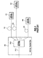
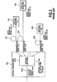
- Figs. 1 to 5 each show an example of a conventional optical communication system with an optical transmitter.
- Fig. 1 shows a configuration of an optical communication system including an optical transmitter with an optical splitter for splitting an optical signal to optical signals with equal optical output levels, and optical receivers connected to the optical transmitter via optical fibers.
- Fig. 2 shows a configuration of an optical communication system including an optical transmitter with an optical splitter for optically splitting an optical signal to signals with equal optical output levels, optical couplers connected to the optical transmitter via optical fibers, and optical receivers connected to the optical couplers via optical fibers.
- Fig. 3 shows a calculation example of a minimum optical reception level in Fig. 1
- Fig. 4 shows a calculation example of a minimum optical reception level in Fig. 2 .
- optical signal is split by an optical transmitter, by a remote variable splitter or by an optical coupler, optical signal passing through the splitting do not always have the same optical levels at the optical receivers.
- the minimum level among the levels received by the optical receivers is called a minimum optical reception level.
- the optical communication system of Fig. 1 includes an optical transmitter 201 with an optical splitter 2012 for splitting an optical signal fed from an optical fiber 2011 to N optical signals with the same optical output level, and N optical receivers 401, 402, ..., and 40N connected to the optical transmitter 201 via N optical fibers 301, 302, ..., and 30N.
- Fig. 3 shows a calculation example of obtaining the minimum optical reception level Pin_min (dBm) in the optical communication system as shown in Fig. 1 .
- the optical output level of the optical fiber 2011 is Pout (dBm)
- the transmission loss of the ith optical fiber is L(i) (dB)
- the optical reception level of the optical receiver (i) is Pin(i) (dBm).
- All the coupling ratios of the optical output levels of the optical splitter 2012 are 1/N. This is because the optical splitter 2012 splits the input optical signal to the same output levels, and the number of the optical receivers connected to the optical splitter 2012, that is, the splitting number of the optical splitter 2012 is N.
- the optical communication system of Fig. 2 comprises: an optical transmitter 501 including an optical splitter 5012 for splitting the optical signal fed through an optical fiber 5011 to optical signals with the same optical output level; N optical couplers 701, 702,..., and 70N connected to the optical transmitter 501 via N optical fibers 601, 602, ..., and 60N; m 1 optical receivers 911, 912, ..., and 91m 1 connected to the first optical coupler 701 via m 1 optical fibers 811, 812, ..., and 81m 1 ; m 2 optical receivers 921, 922, ..., and 92m 2 connected to the second optical coupler 702 via m 2 optical fibers 821, 822, ..., and 82m 2 ; and m N optical receivers 9N1, 9N2, ..., and 9Nm N connected to Nth optical coupler 70N via m N optical fibers 8N1, 8N2, ..., and 8Nm N .
- Fig. 4 shows a calculation example of obtaining the minimum optical reception level Pin_min (dBm) in the optical communication system as shown in Fig. 2 .
- the optical output level of the optical fiber 5011 is Pout (dBm)
- the total transmission loss of the ith and jth optical fibers is L(i,j) (dB)
- the optical reception level of the optical receiver (i,j) is Pin(i,j) (dBm). All the coupling ratios of the optical output levels of the optical splitter 5012 are 1/N.
- the optical splitter 5012 splits the input optical signal to the same output levels, and the number of the optical couplers connected to the optical splitter 5012, that is, the splitting number of the optical splitter 5012 is N.
- the coupling ratio gives the optical loss of the optical splitter 5012 of 10log 10 N (dB) per branch.
- the optical couplers 701, 702, ..., and 70N each have the splitting number m i , and the optical couplers each split the optical input into the same output levels, the optical loss of the optical couplers 701, 702, ..., and 70N is given by 10log 10 m i (dB) per branch.
- the optical reception levels of the optical receivers of the conventional optical communication system depend on the transmission loss L(i), splitting number and transmission loss ⁇ 10log 10 m i + L(i,j) ⁇ .
- optical communication systems as shown in Figs. 1 and 2 have a problem of high cost. This is because in the optical communication systems as shown in Figs. 1 and 2 , it is necessary for the optical receivers with smaller optical reception levels to be more sensitive than the optical receivers with greater optical reception levels to receive the lower intensity light.
- the optical communication systems as shown in Figs. 1 and 2 have the problem of increasing the cost because of the highly sensitive optical receivers.
- the optical communication systems as shown in Figs. 1 and 2 have another problem of having low output efficiency of the optical signals as the optical communication systems in their entirety. This is because receiving the light with the intensity more than necessary, the optical receivers with higher optical reception levels in the optical communication systems as shown in Figs. 1 and 2 waste the light as the total optical communication systems.
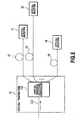
- Fig. 5A shows a conventional two-way optical communication system including one optical transmitting/receiving unit 1 and L optical transmitting/receiving units 2-1 to 2-L, which are connected in a 1 ⁇ L fashion via an optical fiber 3-0, 1 ⁇ L optical coupler 4, and L optical fibers 3-1 to 3-L.
- the optical coupler 4 splits a downlink optical signal with a wavelength ⁇ d transmitted from the optical transmitting/receiving unit 1 to L parts, and transmits them to the optical transmitting/receiving units 2-1 to 2-L.
- the optical coupler 4 combines uplink optical signals with a wavelength ⁇ u transmitted from the optical transmitting/receiving units 2-1 to 2-L, and transmits the combined signal to the optical transmitting/receiving unit 1.
- the optical coupler 4 has equal 1/L coupling ratios so that the downlink optical signal through the optical fiber 3-0 is split to the optical fibers 3-1 to 3-L at the same level, and the uplink optical signals via the optical fibers 3-1 to 3-L are combined to the optical fiber 3-0 at the level with the same coupling loss subtracted.
- the optical fibers 3-1 to 3-L connecting the optical coupler 4 with L optical transmitting/receiving units 2-1 to 2-L as shown in Fig. 5A have different transmission losses in accordance with the transmission distances, though the optical coupler 4 has the equal coupling ratios. Accordingly, although the downlink optical signals have the same level at the input terminals of the optical fibers 3-1 to 3-L as illustrated in Fig. 5B , the optical transmitting/receiving units 2-1 to 2-L have different optical reception levels because of the variations in the transmission loss.
- the uplink optical signals even if they have variations in the optical levels at the output terminals of the optical fibers 3-1 to 3-L, they are combined as they are and received by the optical transmitting/receiving unit 1. Specifically, as illustrated in Fig. 5C , the optical reception levels of the signals sent from the optical transmitting/receiving units 2-1 to 2-L differ at the optical transmitting/receiving unit 1.
- optical transmitting/receiving unit 1 and optical transmitting/receiving units 2-1 to 2-L each require a highly sensitive, wide dynamic range photo-detection circuit that can cope with the variations in the optical reception levels and the minimum optical reception level, thereby increasing the system cost.
- Japanese Patent Application Laid-open No. 4-269023 (1992 ) discloses a method in which slave stations transmit constant level signals to enable a master station to adjust optical attenuation and to transmit different level signals to the slave stations.
- Japanese Patent Application Laid-open No. 11-136192 (1999 ) discloses a method in which a master station adjusts the transmission level for each slave station so that the reception levels of the individual slave stations with different transmission losses become equal.
- the equal coupling ratio for the downlink optical signals with the wavelength ⁇ d is not always equal for the uplink optical signals with the wavelength ⁇ u.
- the coupling ratios are never equal for the wavelength division multiplexed optical signals because the coupling ratios vary in accordance with the individual wavelengths.
- US Patent 6163395 describes a high fidelity, multi-output optical transmission system that is configured utilizing a high power continuous wave YAG laser, multiport splitters, and linearized external modulation.
- An electro-optical modulator design in combination with a continuous wave laser, power splits and couplers attains a multi-octave bandwidth transmitter possessing improved second and third order distortion characteristics.
- the system includes multiple individually modulated transmitter outputs which effectively provides bandwidth multiplication with full redundancy for increased transmission reliability.
- the present invention is implemented to solve the foregoing problems. It is therefore an object of the present invention to provide an optical communication system with an optical output level control function capable of increasing the minimum optical reception level by controlling the optical output levels of its optical transmitter to promote economy of its optical receivers, and by extension of the entire optical communication system, or to provide an optical communication system with an optical output level control function capable of increasing the number of connectable optical receivers.
- Another object of the present invention to provide a two-way optical communication system capable of reducing the dynamic range and sensitivity of photo-detectors in the two-way optical communication system that includes optical couplers for coupling different wavelengths optical signals for its downlink and uplink, or wavelength division multiplexed optical signals, by carrying out the control in such a manner that makes the difference between the maximum optical reception level and minimum optical reception level of each optical transmitting/receiving unit less than a specified value, or that makes its minimum optical reception level more than a specified value.
- an optical communication system comprising: an optical transmitter including a multistage optical variable splitting controller for splitting received light into N parts, and supplying them to N optical fibers, where N is an integer greater than one; and optical receivers for receiving the output light of said optical transmitter via the optical fibers, wherein said multistage optical variable splitting controller regulates its output levels to be delivered to said optical receivers independently by controlling its optical coupling ratios such that optical reception levels equal for all the optical receivers.
- the optical variable splitting controller controls its output levels in such a manner that it does not supply the optical signals with levels more than necessary to the optical receivers connected via the optical fibers with a smaller transmission loss.
- the optical variable splitting controller increases the optical output levels for the optical receivers connected via the optical fibers with a larger transmission loss by exploiting the extra power obtained by reducing the power for the optical receivers connected via the optical fibers with the smaller transmission loss, thereby increasing the optical reception levels of the optical receivers.
- the minimum optical reception level of the optical receivers can be increased.
- the optical variable splitting controller may regulate its optical output levels by controlling its optical coupling ratios such that optical losses from an input of the optical variable splitting controller to inputs of the N optical receivers become equal for all the N optical receivers.
- the optical variable splitting controller may control its output levels in such a manner that it does not supply the optical signals with levels more than necessary to the optical receivers connected via the optical fibers with a smaller transmission loss.
- the optical variable splitting controller may increase the optical output levels for the optical receivers connected via the optical fibers with a larger transmission loss by exploiting the extra power obtained by reducing the power for the optical receivers connected via the optical fibers with the smaller transmission loss, thereby increasing the optical reception levels of the optical receivers.
- the minimum optical reception level of the optical receivers can be increased.
- the optical variable splitting controller may regulate its optical output levels by controlling its optical coupling ratios such that optical losses from an input of the optical variable splitting controller to inputs of the N optical receivers become equal for all of the N optical receivers.
- the optical variable splitting controller may regulate its optical output levels by controlling its optical coupling ratios such that optical losses from an input of one of the remote variable splitters to inputs of the mi optical receivers become equal for all mi optical receivers.
- the minimum optical reception level of the optical receivers can be established at a higher value in the optical communication system.
- implementing the present invention enables increasing the number of the connectable optical receivers, thereby being able to effectively utilizing the light that is wasted in the conventional systems. Thus, it can encourage economy of the optical communication system in its entirety.
- setting the coupling ratios in accordance with the wavelengths used by optical variable couplers can make the difference between the maximum optical reception level and the minimum optical reception level of the individual optical transmitting/receiving units less than the specified value, or make the minimum optical reception level more than the specified value. As a result, it can reduce the dynamic range of the individual optical transmitting/receiving units and the sensitivity of their photo-detectors.
- the first embodiment of the optical communication system in accordance with the present invention comprises: an optical transmitter 11 including an optical variable splitting controller 112 for splitting the optical signal passing through an optical fiber 111 with regulating the optical output levels by controlling the optical coupling ratios; and N optical receivers 31, 32, ..., and 3N connected to the transmitter 11 via N optical fibers 21, 22, ..., and 2N.
- the optical transmitter 11 controls the optical output levels (optical levels to be supplied to the individual optical fibers 21 to 2N) independently of all the optical signals to be sent to the individual optical receivers 31 to 3N via the individual optical fibers 21 to 2N.
- the output levels of the optical signals can differ from each other for respective optical receivers, that is, for the individual optical fibers 21 to 2N connected to the optical receivers 31 to 3N.
- the optical transmitter 11 control the optical output levels such that the optical reception levels become equal for all the N optical receivers.
- the optical output level of the preceding stage of the optical variable splitting controller is Pout (dBm)
- the optical loss from the output of the optical variable splitting controller associated with the optical receiver (i) to the optical receiver is L(i) (dB)
- the optical reception level of the optical receiver (i) is Pin(i) (dBm).
- the optical losses of the optical variable splitting controller are given by 10log10(1/K(i)) (dB).
- the optical output levels are controlled in such a manner that the optical reception levels Pin(i) are denoted as a constant value Pin_con (dBm).
- the optical reception level Pin_con of the present embodiment of the optical communication system is higher than the minimum optical reception level Pin_min of the conventional system. Consequently, it is shown that the optical communication system of the present embodiment is superior to the conventional optical communication system.
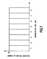
- Fig. 7 shows an example of an optical receiver distribution model in the optical communication system as shown in Fig. 6 .
- the optical receiver distribution model of Fig. 7 shows the transmission losses 1, 2, ..., and 8 (dB), and the number of the optical receivers with the individual transmission losses.
- the minimum optical reception level in the optical receiver distribution model as shown in Fig. 7 is calculated for the conventional optical communication system as shown in Fig. 1 .
- the minimum optical reception level is calculated for the optical communication system of Fig. 6 , when the control of the present embodiment is applied to the optical receiver distribution model as shown in Fig. 7 .
- the minimum optical reception level can be set higher than that of the conventional optical communication system by about 2.9 (dB).
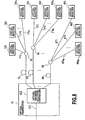
- the second embodiment of the optical communication system in accordance with the present invention comprises: an optical transmitter 41 including an optical variable splitting controller 412 for splitting the optical signal fed from an optical fiber 411 with regulating the optical output levels by controlling the optical coupling ratios; N optical couplers 61, 62, ..., and 6N connected to the optical transmitter 41 via N optical fibers 51, 52, ..., and 5N; and optical receivers 181, 182, ..., and 18m 1 , 281, 282, ..., and 28m 2 , and N81, N82, ..., and N8m N connected to the individual optical couplers 61, 62, ..., and 6N via optical fiber 171, 172, ..., and 17m 1 , 271, 272, ..., and 27m 2 , and N71, N72, ..., and N7m N .
- the optical transmitter 41 controls the optical output levels (optical levels to be supplied to the individual optical fibers 51 to 5N) independently of all the optical signals to be sent to the individual optical couplers 61 to 6N via the individual optical fibers 51 to 5N.
- the output levels of the optical signals can differ from each other for respective optical couplers, that is, for the individual optical fibers 51 to 5N connected to the optical couplers 61 to 6N.
- the minimum optical reception level of the present embodiment of the optical communication system will be compared with that of the conventional example as shown in Fig. 2 .
- the optical coupler connected to the ith optical fiber is denoted as C(i)
- optical receiver (i)max the optical receiver whose optical loss from the optical coupler C(i) to the optical receiver itself is maximum.
- the optical losses of the optical variable splitting controller are given by 10log 10 (1/K(i)max) (dB).
- the optical loss of the optical coupler C(i) is calculated as 10log 10 m i (dB) per branch because the splitting number of the optical coupler C(i) is m i , and the optical coupler splits the input light into parts with the same output levels.
- optical reception level Pin_con_n (dBm) of the present embodiment takes a greater value than the conventional minimum optical reception level Pin_min (dBm) given by equation (4).
- equation (36) - equation (4) is calculated as follows to compare the Pin_con_n with the Pin_min.
- optical reception levels Pin_con_n of the present embodiment of the optical communication system is higher than the minimum optical reception level Pin_min of the conventional system. Consequently, it is proved that the optical communication system of the present embodiment is superior to the conventional optical communication system.
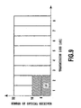
- Fig. 9 shows an example of the optical receiver distribution model in the present embodiment of the optical communication system as shown in Fig. 8 .
- the minimum optical reception level in the optical receiver distribution model as shown in Fig. 9 is calculated for the conventional optical communication system as shown in Fig. 2 .
- the optical loss of each optical coupler is 10log 10 16 (dB) per branch.
- the minimum optical reception level in the second embodiment of the optical communication system of Fig. 8 is calculated when applying the control of the present embodiment to the optical receiver distribution model as shown in Fig. 9 .
- the left-hand side of equation (47) is given by the following expression.
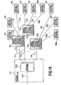
- the third embodiment of the optical communication system in accordance with the present invention comprises: an optical transmitter 101 including an optical splitter 1012 for splitting the optical signal fed from an optical fiber 1011 to optical signals with the same optical output levels; N remote variable splitters 121, 122, ..., and 12N including optical variable splitting controllers 1211, 1221, ..., and 12N1 that are connected to the optical transmitter 101 via N optical fibers 111, 112, ..., and 11N, and splitting the optical signals from the optical fibers 111, 112, ..., and 11N to optical signals with regulating their output levels for the optical receivers by controlling the optical coupling ratios; and m 1 optical receivers 141, 142, ..., and 14m 1 , m 2 optical receivers 241, 242, ..., and 24m 2 , and m N optical receivers N41, N42, ..., and N4m N that are connected to the individual remote variable splitters 121, 122, ..., and 12N via m 1 optical fibers
- the remote variable splitters 121 to 12N independently control the optical output levels of the optical signals which are produced by splitting the optical signal received from the optical fiber 111, and are sent to the individual optical receivers 141, 142, ..., and 14m 1 , the optical output levels of the optical signals which are produced by splitting the optical signal received from the optical fiber 112, and are sent to the individual optical receivers 241, 242, ..., and 24m 2 , and the optical output levels of the optical signals which are produced by splitting the optical signal received from the optical fiber 11N, and are sent to the individual optical receivers N41, N42, ...and N4m N .
- the remote variable splitters control the optical output levels in such manner that the optical losses from the input of the optical variable splitting controllers to the inputs of the m i optical receivers become equal for all the m i optical receivers.
- the optical output level of the preceding stage of each optical variable splitting controller is Pout (dBm)
- the optical loss from the output of the optical variable splitting controller to the optical receivers (i,j) associated with the optical variable splitting controller is L(i,j) (dB)
- the optical reception level of the optical receiver (i,j) is Pin(i,j) (dBm).
- the coupling ratios of the optical output levels of the optical variable splitting controller associated with the optical receivers (i,j) are given by the following equation.
- the optical losses of the optical variable splitting controllers are given by 10log 10 (1/K(i,j)) (dB).
- the optical splitter since the optical splitter has the splitting number N, and carries out the optical splitting such that the signals have the same output levels, the optical splitter has an optical loss of 10log 10 N (dBm) per branch.
- equation (58) - equation (4) is calculated as follows with changing i to u in equation (58) in order to compare the value Pin_con_m(i) (dBm) with Pin_min (dBm) under the same conditions.
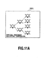
- Figs. 11A and 11B show a configuration of the optical variable splitting controller of the first to third embodiments of the optical communication system in accordance with the present invention, in which the optical variable splitting controller 2001 is configured by combining variable splitters 2002 in multiple stages.
- the variable splitter 2002 has a thin film heater 20023 on the surface of an upper cladding of an optical waveguide 20022. It controls the optical output level by altering the refractive index or phase of the optical waveguide 20022 by the heat from the thin film heater 20023 utilizing the temperature dependence of the refractive index of the optical waveguide, that is, the thermooptic effect.
- n ⁇ 1 n ⁇ 0 + ⁇ T
- the length of the thin film heater 20023 is d
- the phase variation due to the variations of the refractive index of the optical waveguides 20021 and 20022 are ⁇
- the wavelength of the light traveling through the optical waveguides 20021 and 20022 is ⁇ . Then the following equation holds.
- Equations (68) and (69) show that the control of the temperature of the thin film heater 20023 makes it possible to freely control the optical output levels
- Fig. 12 shows an embodiment of a two-way optical communication system in accordance with the present invention.
- a single optical transmitting/receiving unit 1 is connected with L optical transmitting/receiving units 2-1 to 2-L in a one-to-L manner via an optical fiber 3-0, a 1 ⁇ L optifcal varibale coupling unit 10, and optical fibers 3-1 to 3-L.
- the optifcal varibale coupling unit 10 splits a downlink optical signal with a wavelength ⁇ d transmitted from the optical transmitting/receiving unit 1 to L parts, and sends them to the optical transmitting/receiving units 2-1 to 2-L.
- it combines uplink optical signals with a wavelength ⁇ u transmitted from the optical transmitting/receiving units 2-1 to 2-L, and transmits the combined signal to the optical transmitting/receiving unit 1.
- the optifcal varibale coupling unit 10 of the present embodiment has a configuration in which a plurality of 1 ⁇ 2 optical variable couplers 11 are connected successively to implement the 1 ⁇ L coupling.
- a coupling ratio controller 12 controls the coupling ratios of the individual 1 ⁇ 2 optical variable couplers 11 considering the transmission losses of the optical fibers 3-1 to 3-L and the wavelength, thereby carrying out variable control of the 1 ⁇ L coupling ratios in their entirety.
- the 1 ⁇ 2 optical variable couplers 11 Mach-Zehnder interferometer type couplers are used whose coupling ratios are varied by temperature control or by electric field control, for example.
- the 1 ⁇ 2 optical variable couplers can be configured as shown in Fig. 11B .
- the coupling ratio Since the coupling ratio has wavelength dependence, it must be controlled in accordance with the wavelength used. A control example will be described below.
- the coupling ratio controller 12 of the optifcal varibale coupling unit 10 stores a premeasured optical transmission level Pout(1) of the optical transmitting/receiving unit 1 and premeasured individual optical reception levels Pin(21) to Pin(2L) of the optical transmitting/receiving units 2-1 to 2-L.
- the individual total optical losses between the optical transmitting/receiving unit 1 and the optical transmitting/receiving units 2-1 to 2-L are obtained as the difference between the premeasured Pout(1) and Pin(21), ..., and the difference between the Pout(1) and Pin(2L), respectively.
- the individual optical losses depend on the transmission loss of the optical fiber 3-0, the coupling ratios (coupling losses) of the optifcal varibale coupling unit 10 (individual 1 ⁇ 2 optical variable couplers 11 on the passage) and the transmission losses of the individual optical fibers 3-1 to 3-L, and the coupling losses depend on the wavelength. Accordingly, the coupling ratios that make the difference between the maximum and minimum values of the individual total optical losses less than a specified value at the individual wavelengths can be obtained by carrying out calculation with varying the coupling ratios at the wavelengths ⁇ d and ⁇ u.
- the coupling ratio controller 12 controls the individual 1 ⁇ 2 optical variable couplers 11 to set their coupling ratios at such values that can make the following differences less than the specified values.
- the differences are the difference between the minimum optical reception level and maximum optical reception level of the downlink optical signals with the wavelength ⁇ d received by the optical transmitting/receiving units 2-1 to 2-L, and the difference between the minimum optical reception level and maximum optical reception level of the uplink optical signals with the wavelength ⁇ u sent from the optical transmitting/receiving units 2-1 to 2-L to the optical transmitting/receiving unit 1.
- Fig. 13 illustrates a first control example of the 1 ⁇ 2 optical variable couplers 11.
- a first total optical loss between the transmitter and a receiver at wavelength ⁇ d is L1( ⁇ d)
- a second total optical loss is L2( ⁇ d)
- a first total optical loss between the transmitter and the receiver at the wavelength ⁇ u is L1( ⁇ u)
- a second total optical loss is L2( ⁇ u)
- the coupling ratios are controlled such that the difference between the maximum value (L1( ⁇ d)) and the minimum value (L2( ⁇ u)) becomes less than a specified value.
- the coupling ratio is set that makes the difference between the maximum value and the minimum value of the total optical loss between the transmitter and receiver at each wavelength less than the specified value.
- the coupling ratio controller 12 of the optifcal varibale coupling unit 10 stores a premeasured optical transmission level Pout(1) of the optical transmitting/receiving unit 1 and premeasured individual optical reception levels Pin(21) to Pin(2L) of the optical transmitting/receiving units 2-1 to 2-L, and premeasured individual optical transmission levels Pout(21) to Pout(2L) of the optical transmitting/receiving units 2-1 to 2-L.
- the individual total optical losses between the optical transmitting/receiving unit 1 and the optical transmitting/receiving units 2-1 to 2-L are each obtained as the difference between the premeasured Pout(1) and Pin(21), ..., and the difference between the Pout(1) and Pin(2L).
- the optical reception levels of the downlink optical signals at the optical transmitting/receiving units 2-1 to 2-L and the optical reception levels of the uplink optical signals at the optical transmitting/receiving unit 1 depend on the transmission loss of the optical fiber 3-0, the coupling ratios (coupling losses) of the optifcal varibale coupling unit 10 and the transmission losses of the individual optical fibers 3-1 to 3-L, and the coupling losses depend on the wavelength. Accordingly, the coupling ratios that make the minimum values of the individual received levels greater than a specified value can be obtained by carrying out calculation with varying the coupling ratios at the wavelengths ⁇ d and ⁇ u.
- the coupling ratio controller 12 can place the minimum optical reception levels of the optical transmitting/receiving unit 1 and optical transmitting/receiving units 2-1 to 2-L at a value greater than the specified value by setting the coupling ratios of the individual 1 ⁇ 2 optical variable couplers 11 by controlling them.
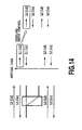
- Fig. 14 illustrates a second control example of the 1 ⁇ 2 optical variable couplers 11.
- a first total optical loss between the transmitter and a receiver at wavelength ⁇ d is L1( ⁇ d)
- a second total optical loss is L2( ⁇ d)
- a first total optical loss between the transmitter and the receiver at the wavelength ⁇ u is L1( ⁇ u)
- a second total optical loss is L2( ⁇ u)
- the coupling ratios are controlled such that the maximum value (L1( ⁇ d)) is less than the specified value, that is, the minimum values of the individual optical reception levels become greater than the specified value.
- the coupling ratios are calculated such that the minimum reception levels become greater than a specified value for the respective wavelengths.
- the coupling ratio controller 12 of the optifcal varibale coupling unit 10 stores premeasured individual optical transmission levels Pout(21) to Pout(2L) of the optical transmitting/receiving units 2-1 to 2-L, and measures and stores the individual optical reception levels Pin(101) to Pin(10L) of the uplink optical signals at the optifcal varibale coupling unit 10.
- the means for measuring the individual optical reception levels Pin(101) to Pin(10L) of the incoming uplink optical signals from the optical fibers 3-1 to 3-L to the optifcal varibale coupling unit 10 is omitted from Fig. 12 .
- the individual optical losses between the optifcal varibale coupling unit 10 and the optical transmitting/receiving units 2-1 to 2-L are each obtained as the difference between the Pout(21) and Pin(101), ..., and the difference between the Pout(2L) and Pin(10L).
- the individual total optical losses between the optical transmitting/receiving unit 1 and the optical transmitting/receiving units 2-1 to 2-L depend on the transmission loss of the optical fiber 3-0, coupling ratios (coupling losses) at the optifcal varibale coupling unit 10 and the transmission losses (measured values) of the individual optical fibers 3-1 to 3-L, and the coupling losses depend on the wavelength.
- the coupling ratios that make the difference between the maximum and minimum values of the individual total optical losses less than a specified value at the individual wavelengths can be obtained by carrying out calculation with varying the coupling ratios at the wavelengths ⁇ d and ⁇ u.
- the coupling ratio controller 12 controls the individual 1 ⁇ 2 optical variable couplers 11 to set their coupling ratios at such values that can make the following differences less than the specified values.
- the differences are the difference between the minimum optical reception level and maximum optical reception level of the downlink optical signals with the wavelength ⁇ d received by the optical transmitting/receiving units 2-1 to 2-L, and the difference between the minimum optical reception level and maximum optical reception level of the uplink optical signals with the wavelength ⁇ u sent from the optical transmitting/receiving units 2-1 to 2-L to the optical transmitting/receiving unit 1.
- the coupling ratio is set that makes the difference between the maximum value and the minimum value of the total optical loss between the transmitter and receiver at each wavelength less than the specified value.
- the optical reception levels of the uplink optical signals at the optical transmitting/receiving unit 1 depend on the individual optical transmission levels Pout(21) to Pout(2L), the coupling ratios (coupling losses) of the optifcal varibale coupling unit 10 and the transmission losses of the individual optical fibers 3-1 to 3-L, and the coupling losses depend on the wavelength. Accordingly, the coupling ratios that make the minimum values of the individual received levels greater than the specified value can be obtained by carrying out calculation with varying the coupling ratios at the wavelengths ⁇ d and ⁇ u.
- the coupling ratio controller 12 can place the minimum optical reception levels of the optical transmitting/receiving unit 1 and optical transmitting/receiving units 2-1 to 2-L at a value greater than the specified value by setting the coupling ratios of the individual 1 ⁇ 2 optical variable couplers 11 by controlling them.
- the coupling ratios are calculated such that the minimum reception levels become greater than a specified value for the respective wavelengths.
- An optical communication system can increase a minimum optical reception level or the number of connectable optical receivers by controlling optical output levels of its optical transmitter.
- the optical communication system includes the optical transmitter having an optical variable splitting controller for splitting received light into N parts and supplies them to N optical fibers, and N optical receivers for receiving the signals sent via the N optical fibers.
- the optical variable splitting controller regulates its optical output levels to be supplied to the N optical fibers by controlling the optical coupling ratios.
- the optical variable splitting controller may regulate its optical output levels by controlling its optical coupling ratios such that optical losses from its input to inputs of the N optical receivers become equal for all the N optical receivers.
Landscapes
- Engineering & Computer Science (AREA)
- Computing Systems (AREA)
- Physics & Mathematics (AREA)
- Electromagnetism (AREA)
- Computer Networks & Wireless Communication (AREA)
- Signal Processing (AREA)
- Optical Communication System (AREA)
Claims (4)
- Optisches Kommunikationssystem, mit:einem optischen Transmitter (11), der eine mehrstufige optische variable Splittungssteuerung (112, 2001) zum Splitten von empfangenem Licht in N Anteile umfasst, und diese N optischen Lichtwellenleitern (21, 22, ... 2N) zuführt, wobei N eine ganze Zahl größer als eins ist; undoptischen Empfängern (31, 32, ... , 3N) zum Empfangen des Ausgabelichts des optischen Transmitters (11) über die optischen Lichtwellenleiter, wobeidie mehrstufige optische variable Splittungssteuerung (112, 2201) ihre an die optischen Empfänger (31, 32, ... , 3N) zu übermittelnden Ausgangspegel unabhängig reguliert, durch Steuern ihrer optischen Koppelverhältnisse derart, dass optische Empfangspegel für alle optischen Empfänger gleich werden.
- Optisches Kommunikationssystem gemäß Anspruch 1, ferner mit:N optischen Kopplern (61, 62, ... , 6N) zum Empfangen von Ausgaben des optischen Transmitters (11) über die N optischen Lichtwellenleiter (21, 22, ... , 2N), wobei jeder der N optischen Koppler sein empfangenes Signal an mi optische Lichtwellenleiter (171, 172, N7mN) übermittelt, wobei das Suffix i von eins bis N variiert; undmi optischen Empfängern (181, 182, ... , N8mN) zum Empfangen von Ausgaben eines der N optischen Koppler (61, 62, ... , 6N) über die mi optischen Lichtwellenleiter (181, 182, ... , NBmN) .
- Optisches Kommunikationssystem gemäß Anspruch 2, wobei ein optischer Empfänger, dessen optische Dämpfung von einem Ausgang eines verbundenen der optischen Koppler zu einem Eingang des einen optischen Empfängers die größte unter mi optischen Empfängern ist, die mit dem einen der optischen Koppler verbunden sind, für jeden der optischen Koppler ausgewählt wird, und die mehrstufige optische variable Splittungssteuerung (112, 2001) optische Ausgangspegel der ausgewählten N optischen Empfänger reguliert, durch Steuern ihrer optischen Koppelverhältnisse derart, dass optische Empfangspegel für alle der N optischen Empfänger gleich werden.
- Optisches Kommunikationssystem gemäß Anspruch 1, wobei der mehrstufige optische Splitter ferner angeordnet ist, um empfangenes Licht in N Anteile mit gleichen Ausgangspegeln zu splitten, und wobei das optische Kommunikationssystem ferner aufweist:N entfernt liegende variable Splitter (121, 122, ... , 12N) zum Empfangen von Ausgaben des optischen Transmitters (11) über die N optischen Lichtwellenleiter, wobei jeder der N entfernt liegenden variablen Splitter eine mehrstufige optische variable Splittungssteuerung umfasst, die ein empfangenes optisches Signal in mi Anteile splittet und sie mi optischen Lichtwellenleitern (131, 132, ... , 13N) zuführt, wobei das Suffix i von eins bis N variiert; undmi optische Empfänger zum Empfangen von Ausgaben von einem der N entfernt liegenden variablen Splitter über die mi optischen Lichtwellenleiter.
Applications Claiming Priority (4)
| Application Number | Priority Date | Filing Date | Title |
|---|---|---|---|
| JP2001327483A JP2003134049A (ja) | 2001-10-25 | 2001-10-25 | 光出力レベル制御機能付き光通信システム |
| JP2001327483 | 2001-10-25 | ||
| JP2002045955A JP2003249901A (ja) | 2002-02-22 | 2002-02-22 | 双方向光通信システム |
| JP2002045955 | 2002-02-22 |
Publications (3)
| Publication Number | Publication Date |
|---|---|
| EP1306990A2 EP1306990A2 (de) | 2003-05-02 |
| EP1306990A3 EP1306990A3 (de) | 2005-02-09 |
| EP1306990B1 true EP1306990B1 (de) | 2009-04-29 |
Family
ID=26624097
Family Applications (1)
| Application Number | Title | Priority Date | Filing Date |
|---|---|---|---|
| EP02257379A Expired - Lifetime EP1306990B1 (de) | 2001-10-25 | 2002-10-23 | Optisches Übertragungssystem mit Verfahren zur Steuerung seines Ausgangspegels |
Country Status (3)
| Country | Link |
|---|---|
| US (1) | US7236708B2 (de) |
| EP (1) | EP1306990B1 (de) |
| DE (1) | DE60232126D1 (de) |
Families Citing this family (11)
| Publication number | Priority date | Publication date | Assignee | Title |
|---|---|---|---|---|
| US8086103B2 (en) * | 2004-04-29 | 2011-12-27 | Alcatel Lucent | Methods and apparatus for communicating dynamic optical wavebands (DOWBs) |
| US8725555B2 (en) * | 2011-09-19 | 2014-05-13 | Alliance Enterprises, Inc. | Vendor performance management system and method for determining a vendor's contribution value and vendor services score |
| JP2013140275A (ja) * | 2012-01-05 | 2013-07-18 | Sumitomo Electric Ind Ltd | 光分岐・合成装置 |
| EP2823581A1 (de) | 2012-03-05 | 2015-01-14 | Alcatel Lucent | Flexibler optischer modulator für erweiterte modulationsformate mit optischen kopplern mit asymmetrischer leistungsverzweigung |
| US20160248519A1 (en) * | 2015-02-19 | 2016-08-25 | Coriant Advanced Technology, LLC | Variable power splitter for equalizing output power |
| CN113544983B (zh) | 2019-03-22 | 2025-05-02 | 英国电讯有限公司 | 用于进行量子密钥分发的系统和方法 |
| US11881893B2 (en) * | 2020-02-12 | 2024-01-23 | Nippon Telegraph And Telephone Corporation | Optical communication system and dispersion compensation method |
| JP7414081B2 (ja) | 2020-02-12 | 2024-01-16 | 日本電信電話株式会社 | 光通信システム及び制御方法 |
| US12143157B2 (en) * | 2020-07-29 | 2024-11-12 | Nippon Telegraph And Telephone Corporation | Branch ratio setting system, method for producing optical communication system and optical branch device |
| WO2022024270A1 (ja) * | 2020-07-29 | 2022-02-03 | 日本電信電話株式会社 | 光給電システム |
| EP4440005A1 (de) * | 2023-03-31 | 2024-10-02 | Nokia Solutions and Networks Oy | Pon mit aktiver anpassung des optischen verteilungsnetzwerks |
Family Cites Families (42)
| Publication number | Priority date | Publication date | Assignee | Title |
|---|---|---|---|---|
| US3874779A (en) * | 1973-07-05 | 1975-04-01 | Corning Glass Works | Variable ratio light coupler |
| FR2284892A1 (fr) * | 1974-09-13 | 1976-04-09 | Thomson Csf | Coupleur variable pour fibres optiques |
| US4135779A (en) * | 1976-08-02 | 1979-01-23 | Corning Glass Works | Variable ratio optical junction device |
| US4431260A (en) * | 1979-02-26 | 1984-02-14 | General Dynamics, Pomona Division | Method of fabrication of fiber optic coupler |
| US4783851A (en) * | 1984-01-27 | 1988-11-08 | Yokogawa Electric Corporation | Optical communication system |
| DE3506569A1 (de) * | 1985-02-25 | 1986-08-28 | Manfred Prof. Dr. 7900 Ulm Börner | Integrierte resonatormatrix zum wellenlaengenselektiven trennen bzw. zusammenfuegen von kanaelen im frequenzbereich der optischen nachrichtentechnik |
| GB8727846D0 (en) * | 1987-11-27 | 1987-12-31 | British Telecomm | Optical communications network |
| US4787693A (en) * | 1987-11-02 | 1988-11-29 | American Telephone And Telegraph Company, At&T Bell Laboratories | Passive star coupler |
| US4873681A (en) * | 1988-01-26 | 1989-10-10 | Bell Communications Research, Inc. | Hybrid optical and electronic packet switch |
| US4943136A (en) * | 1988-12-09 | 1990-07-24 | The Boeing Company | Optical backplane interconnection |
| US5221983A (en) * | 1989-01-19 | 1993-06-22 | Bell Communications Research, Inc. | Passive photonic loop architecture employing wavelength multiplexing |
| CA2009352C (en) * | 1989-02-07 | 1995-02-28 | Masao Kawachi | Guided-wave optical branching components and optical switches |
| WO1990009710A1 (de) * | 1989-02-20 | 1990-08-23 | Licentia Patent-Verwaltungs-Gmbh | Sternförmiges netz für die datenkommunikation zwischen stationen |
| JP2754774B2 (ja) * | 1989-03-31 | 1998-05-20 | 株式会社島津製作所 | 導波路型光回路素子 |
| JPH0795130B2 (ja) * | 1990-01-26 | 1995-10-11 | 株式会社精工技研 | 可変型光分岐合流器 |
| JP2633073B2 (ja) * | 1990-09-07 | 1997-07-23 | 株式会社精工技研 | 可変型光減衰器 |
| JPH04269023A (ja) | 1991-02-25 | 1992-09-25 | Nippon Telegr & Teleph Corp <Ntt> | 光伝送装置 |
| US5136669A (en) * | 1991-03-15 | 1992-08-04 | Sperry Marine Inc. | Variable ratio fiber optic coupler optical signal processing element |
| CA2083983A1 (en) * | 1992-01-27 | 1993-07-28 | Kishor P. Gadkaree | Low expansion composition for packaging optical waveguide couplers |
| JP3269505B2 (ja) * | 1992-11-19 | 2002-03-25 | 三菱瓦斯化学株式会社 | 高分子光導波路型光スターカプラ |
| DE69428630T2 (de) * | 1993-06-21 | 2002-08-01 | Nippon Telegraph And Telephone Corp., Tokio/Tokyo | Optischer Signal-Prozessor, Verfahren zu seiner Steuerung, Verfahren zu seiner Konstruktion, und Verfahren zu seiner Herstellung |
| JPH0879185A (ja) | 1994-09-02 | 1996-03-22 | Nec Corp | 光出力制御回路及びそれを用いた光通信装置 |
| US5680234A (en) * | 1994-10-20 | 1997-10-21 | Lucent Technologies Inc. | Passive optical network with bi-directional optical spectral slicing and loop-back |
| US5574589A (en) * | 1995-01-09 | 1996-11-12 | Lucent Technologies Inc. | Self-amplified networks |
| US5661585A (en) * | 1995-02-27 | 1997-08-26 | Lucent Technologies Inc. | Passive optical network having amplified LED transmitters |
| US5710653A (en) * | 1995-03-06 | 1998-01-20 | Fiber Optic Network Solutions Corp. | Linear multi-output optical transmitter system |
| US5808764A (en) * | 1995-12-28 | 1998-09-15 | Lucent Technologies, Inc. | Multiple star, passive optical network based on remote interrogation of terminal equipment |
| JP3720112B2 (ja) * | 1996-03-18 | 2005-11-24 | 富士通株式会社 | 波長分割多重が適用されるシステム及び光パワー制御装置 |
| JPH1041897A (ja) | 1996-07-19 | 1998-02-13 | Oki Electric Ind Co Ltd | 光伝送システム及び光送受信装置 |
| JPH10228007A (ja) * | 1997-02-13 | 1998-08-25 | Nec Corp | 光導波路型電気制御可変アッティネータ |
| JPH11136192A (ja) | 1997-10-24 | 1999-05-21 | Nec Corp | Pds方式の光通信システム及びその通信方法 |
| JPH11275028A (ja) * | 1998-03-20 | 1999-10-08 | Fujitsu Ltd | 光通信システム |
| US6411417B1 (en) * | 1998-09-22 | 2002-06-25 | Nortel Networks Limited | Optical equalizer |
| USH2075H1 (en) * | 1998-10-13 | 2003-08-05 | At&T Corp. | Restorable architectures for fiber-based broadband local access networks |
| JP4169878B2 (ja) | 1999-08-19 | 2008-10-22 | 三菱電機株式会社 | ポイント−マルチポイント光通信システム |
| JP2001100122A (ja) * | 1999-09-30 | 2001-04-13 | Seikoh Giken Co Ltd | 分岐比可変形光分岐結合器および接続比可変形光結合器 |
| JP2001268055A (ja) | 2000-03-23 | 2001-09-28 | Nippon Telegr & Teleph Corp <Ntt> | 光通信方式 |
| JP2001339348A (ja) * | 2000-05-26 | 2001-12-07 | Nec Corp | 光カプラ監視システム |
| JP2001339344A (ja) * | 2000-05-29 | 2001-12-07 | Hitachi Ltd | 光信号切替装置 |
| US6915079B1 (en) * | 2000-05-30 | 2005-07-05 | Nortel Networks, Ltd. | Non-return optical star coupler |
| US6490391B1 (en) * | 2000-07-12 | 2002-12-03 | Oluma, Inc. | Devices based on fibers engaged to substrates with grooves |
| JP3567867B2 (ja) | 2000-08-10 | 2004-09-22 | 日本電気株式会社 | 光通信システム及び光受信レベル調整方法 |
-
2002
- 2002-10-22 US US10/277,489 patent/US7236708B2/en not_active Expired - Fee Related
- 2002-10-23 DE DE60232126T patent/DE60232126D1/de not_active Expired - Lifetime
- 2002-10-23 EP EP02257379A patent/EP1306990B1/de not_active Expired - Lifetime
Also Published As
| Publication number | Publication date |
|---|---|
| US20030095314A1 (en) | 2003-05-22 |
| EP1306990A3 (de) | 2005-02-09 |
| US7236708B2 (en) | 2007-06-26 |
| DE60232126D1 (de) | 2009-06-10 |
| EP1306990A2 (de) | 2003-05-02 |
Similar Documents
| Publication | Publication Date | Title |
|---|---|---|
| EP1306990B1 (de) | Optisches Übertragungssystem mit Verfahren zur Steuerung seines Ausgangspegels | |
| US7340114B2 (en) | Optical waveguide device and optical modulator | |
| US6282361B1 (en) | Multi-channel variable optical attenuator | |
| ITMI972715A1 (it) | Equalizzatore ottico per un sistema di comunicazione ottica multiplato in lunghezza d'onda | |
| US6208440B1 (en) | Optical wavelength filter and optical demultiplexer | |
| EP3321720B1 (de) | Optische interferenzfiltervorrichtung, insbesondere für eine optische wellenlängenkopplungsvorrichtung | |
| US6633430B1 (en) | Booster amplifier with spectral control for optical communications systems | |
| US11509396B2 (en) | Polarization multi/demultiplexed optical transceiver circuit | |
| US6907200B2 (en) | Dispersion compensating module, line switching apparatus and optical communication system | |
| KR20020074221A (ko) | 파장 분산 보상 모듈 및 그것을 포함하는 광전송 시스템 | |
| US6856456B2 (en) | Device and system for the optical transmission of data between satellites | |
| US7209662B2 (en) | Wavelength multiplex transmission device | |
| US6782168B2 (en) | Apparatus for and method of monitoring wavelength multiplexed signal light as well as optical transmission system using the same | |
| WO2006030524A1 (ja) | 光挿入分岐装置 | |
| US6978064B2 (en) | Variable optical filter and optical transmission system using same, and method of controlling variable optical filter | |
| JPH06224860A (ja) | 光分散補償方法および光分散補償器 | |
| US11336370B1 (en) | Integrated multi-channel photonics transmitter chip having variable power dividers | |
| US6731836B2 (en) | Dispersion compensator | |
| JP2020140001A (ja) | モード分岐デバイス | |
| KR20000025674A (ko) | 파장분할다중 방식의 양방향 광전송망을 위한 양방향 광증폭 장치 | |
| US4542536A (en) | Device and method for reducing level dynamics in an optical transmission system | |
| US20080031622A1 (en) | Bidirectional Router and a Method of Bidirectional Amplification | |
| JP6457966B2 (ja) | 光伝送システム | |
| JP3319681B2 (ja) | 光伝送路シミュレータ | |
| JP2003249901A (ja) | 双方向光通信システム |
Legal Events
| Date | Code | Title | Description |
|---|---|---|---|
| PUAI | Public reference made under article 153(3) epc to a published international application that has entered the european phase |
Free format text: ORIGINAL CODE: 0009012 |
|
| AK | Designated contracting states |
Designated state(s): AT BE BG CH CY CZ DE DK EE ES FI FR GB GR IE IT LI LU MC NL PT SE SK TR |
|
| AX | Request for extension of the european patent |
Extension state: AL LT LV MK RO SI |
|
| PUAL | Search report despatched |
Free format text: ORIGINAL CODE: 0009013 |
|
| AK | Designated contracting states |
Kind code of ref document: A3 Designated state(s): AT BE BG CH CY CZ DE DK EE ES FI FR GB GR IE IT LI LU MC NL PT SE SK TR |
|
| AX | Request for extension of the european patent |
Extension state: AL LT LV MK RO SI |
|
| RIC1 | Information provided on ipc code assigned before grant |
Ipc: 7H 04B 10/207 B Ipc: 7H 04B 10/213 A |
|
| 17P | Request for examination filed |
Effective date: 20050802 |
|
| AKX | Designation fees paid |
Designated state(s): DE FR GB |
|
| GRAP | Despatch of communication of intention to grant a patent |
Free format text: ORIGINAL CODE: EPIDOSNIGR1 |
|
| GRAS | Grant fee paid |
Free format text: ORIGINAL CODE: EPIDOSNIGR3 |
|
| GRAA | (expected) grant |
Free format text: ORIGINAL CODE: 0009210 |
|
| AK | Designated contracting states |
Kind code of ref document: B1 Designated state(s): DE FR GB |
|
| REG | Reference to a national code |
Ref country code: GB Ref legal event code: FG4D |
|
| REF | Corresponds to: |
Ref document number: 60232126 Country of ref document: DE Date of ref document: 20090610 Kind code of ref document: P |
|
| PLBE | No opposition filed within time limit |
Free format text: ORIGINAL CODE: 0009261 |
|
| STAA | Information on the status of an ep patent application or granted ep patent |
Free format text: STATUS: NO OPPOSITION FILED WITHIN TIME LIMIT |
|
| 26N | No opposition filed |
Effective date: 20100201 |
|
| PGFP | Annual fee paid to national office [announced via postgrant information from national office to epo] |
Ref country code: FR Payment date: 20121018 Year of fee payment: 11 Ref country code: DE Payment date: 20121017 Year of fee payment: 11 |
|
| PGFP | Annual fee paid to national office [announced via postgrant information from national office to epo] |
Ref country code: GB Payment date: 20121017 Year of fee payment: 11 |
|
| REG | Reference to a national code |
Ref country code: DE Ref legal event code: R119 Ref document number: 60232126 Country of ref document: DE |
|
| GBPC | Gb: european patent ceased through non-payment of renewal fee |
Effective date: 20131023 |
|
| PG25 | Lapsed in a contracting state [announced via postgrant information from national office to epo] |
Ref country code: GB Free format text: LAPSE BECAUSE OF NON-PAYMENT OF DUE FEES Effective date: 20131023 |
|
| REG | Reference to a national code |
Ref country code: FR Ref legal event code: ST Effective date: 20140630 |
|
| PG25 | Lapsed in a contracting state [announced via postgrant information from national office to epo] |
Ref country code: DE Free format text: LAPSE BECAUSE OF NON-PAYMENT OF DUE FEES Effective date: 20140501 Ref country code: FR Free format text: LAPSE BECAUSE OF NON-PAYMENT OF DUE FEES Effective date: 20131031 |
|
| REG | Reference to a national code |
Ref country code: DE Ref legal event code: R079 Ref document number: 60232126 Country of ref document: DE Free format text: PREVIOUS MAIN CLASS: H04B0010213000 Ipc: H04B0010270000 |
|
| REG | Reference to a national code |
Ref country code: DE Ref legal event code: R079 Ref document number: 60232126 Country of ref document: DE Free format text: PREVIOUS MAIN CLASS: H04B0010213000 Ipc: H04B0010270000 Effective date: 20141007 Ref country code: DE Ref legal event code: R119 Ref document number: 60232126 Country of ref document: DE Effective date: 20140501 |