EP1306352A2 - Vorrichtung zum Trocknen von Schlamm mit einer Heizeinrichtung in einer Transporteinrichtung - Google Patents
Vorrichtung zum Trocknen von Schlamm mit einer Heizeinrichtung in einer Transporteinrichtung Download PDFInfo
- Publication number
- EP1306352A2 EP1306352A2 EP02023807A EP02023807A EP1306352A2 EP 1306352 A2 EP1306352 A2 EP 1306352A2 EP 02023807 A EP02023807 A EP 02023807A EP 02023807 A EP02023807 A EP 02023807A EP 1306352 A2 EP1306352 A2 EP 1306352A2
- Authority
- EP
- European Patent Office
- Prior art keywords
- screw
- sludge
- transport
- paddle shaft
- transport screw
- Prior art date
- Legal status (The legal status is an assumption and is not a legal conclusion. Google has not performed a legal analysis and makes no representation as to the accuracy of the status listed.)
- Granted
Links
Images


Classifications
-
- C—CHEMISTRY; METALLURGY
- C02—TREATMENT OF WATER, WASTE WATER, SEWAGE, OR SLUDGE
- C02F—TREATMENT OF WATER, WASTE WATER, SEWAGE, OR SLUDGE
- C02F11/00—Treatment of sludge; Devices therefor
- C02F11/12—Treatment of sludge; Devices therefor by de-watering, drying or thickening
- C02F11/121—Treatment of sludge; Devices therefor by de-watering, drying or thickening by mechanical de-watering
- C02F11/125—Treatment of sludge; Devices therefor by de-watering, drying or thickening by mechanical de-watering using screw filters
-
- C—CHEMISTRY; METALLURGY
- C02—TREATMENT OF WATER, WASTE WATER, SEWAGE, OR SLUDGE
- C02F—TREATMENT OF WATER, WASTE WATER, SEWAGE, OR SLUDGE
- C02F11/00—Treatment of sludge; Devices therefor
- C02F11/12—Treatment of sludge; Devices therefor by de-watering, drying or thickening
- C02F11/13—Treatment of sludge; Devices therefor by de-watering, drying or thickening by heating
-
- F—MECHANICAL ENGINEERING; LIGHTING; HEATING; WEAPONS; BLASTING
- F26—DRYING
- F26B—DRYING SOLID MATERIALS OR OBJECTS BY REMOVING LIQUID THEREFROM
- F26B17/00—Machines or apparatus for drying materials in loose, plastic, or fluidised form, e.g. granules, staple fibres, with progressive movement
- F26B17/18—Machines or apparatus for drying materials in loose, plastic, or fluidised form, e.g. granules, staple fibres, with progressive movement with movement performed by rotating helical blades or other rotary conveyors which may be heated moving materials in stationary chambers, e.g. troughs
- F26B17/20—Machines or apparatus for drying materials in loose, plastic, or fluidised form, e.g. granules, staple fibres, with progressive movement with movement performed by rotating helical blades or other rotary conveyors which may be heated moving materials in stationary chambers, e.g. troughs the axis of rotation being horizontal or slightly inclined
- F26B17/205—Machines or apparatus for drying materials in loose, plastic, or fluidised form, e.g. granules, staple fibres, with progressive movement with movement performed by rotating helical blades or other rotary conveyors which may be heated moving materials in stationary chambers, e.g. troughs the axis of rotation being horizontal or slightly inclined with multiple chambers, e.g. troughs, in superimposed arrangement
-
- F—MECHANICAL ENGINEERING; LIGHTING; HEATING; WEAPONS; BLASTING
- F26—DRYING
- F26B—DRYING SOLID MATERIALS OR OBJECTS BY REMOVING LIQUID THEREFROM
- F26B2200/00—Drying processes and machines for solid materials characterised by the specific requirements of the drying goods
- F26B2200/18—Sludges, e.g. sewage, waste, industrial processes, cooling towers
Definitions
- the invention relates to a device for drying sludge, in particular sewage or Digested sludge, with a transport device for conveying the sludge between one Product entry and a product discharge, and a heating device for heating the Sludge in the transport device, wherein the transport device at least one Includes trough, and wherein in an interior of the at least one trough a conveyor screw is arranged with wings for circulating and conveying the sludge.
- Devices of this type are used to treat the sewage or digested sludge occurring in sewage treatment plants prepare for landfilling with a high pollutant load and high water content. Contaminated soil, such as after a chemical accident, a garbage accident or the like can be treated in such a device become.
- the sludge to be dried which was previously used, for example, as part of a drainage can be treated, is introduced via the product entry in a trough.
- a worm shaft is arranged in the trough Promotes mud.
- several troughs are in a cascade arranged one above the other.
- the sludge to be dried passes along the cascade from the Product entry for a product discharge.
- the mud in each of the troughs promoted from a trough entry to a trough discharge.
- From the trough discharge of a parent The sludge enters the trough in a trough below.
- An intermediate section is formed for troughs for guiding the sludge.
- both the troughs and the screw conveyors heated so that the sludge is heated and water components evaporate.
- To this Purpose are double-walled trough walls so that the trough walls heat from one Medium, especially oil can be flowed through.
- a Shaft of the screw conveyor is also double-walled, so that the shaft of can flow through the heated medium.
- each of the troughs is connected to the suction device.
- the object of the present form is to provide an improved device as described in the introduction To create species with an increased efficiency in terms of sludge drying.
- the invention also has the advantage that a much better mixing of the sludge to be dried takes place. To this In this way, new dry goods parts are brought into contact with the heating device and thereby dried.
- the continuous mixing of the sludge leads to particles of the sludge, which are initially surrounded by other particles of the sludge so that not with the heated surfaces, e.g. heated troughs or snail wings, in contact occur, are exposed so that these particles can be dried.
- the continuous circulation using the paddle shaft prevents the formation of larger clumps in the troughs, which reduce the effectiveness of the drying process.
- An expedient development of the invention provides that the paddle shaft above the Transport screw is arranged. As a result, the cross section of the troughs is transverse to the longitudinal direction the transport screw is kept as low as possible. This has the advantage that a The smallest possible evaporation area is reached, which is in connection with the design of Suction devices for sucking off the vapors formed during the drying of the sludge is appropriate.
- paddle waves provide an expedient embodiment the invention that when the sludge is circulated, the paddles of a paddle shaft and the paddles of the at least one further paddle shaft interlock.
- the invention particularly expediently designed that the paddle shaft above the screw conveyor and the at least one further paddle shaft above the at least one further screw conveyor are arranged so that a central axis of the Paddle shaft in the longitudinal direction and a central axis of the screw conveyor in the longitudinal direction and a central axis of the at least one further paddle shaft in the longitudinal direction and a Central axis of the at least one further screw conveyor in the longitudinal direction in each case lie essentially in a vertical plane.
- the paddles of the at least one further paddle shaft and the wings of the at least one comb each other auger while circulating the sludge can additionally be provided that the paddles of the at least one further paddle shaft and the wings of the at least one comb each other auger while circulating the sludge. This significantly reduces the thickness of lumps of the dry material, for example by half.
- the transport screw and / or the at least one further screw conveyor each as a worm shaft are trained, creating a mechanically stable and high stress sufficient conveying screw is created in the conveyance of the sludge in the troughs.
- the screw conveyor and the at least one further screw conveyor are mechanically coupled to each other, whereby the rotational movement of the screw conveyor and the at least one further screw conveyor can be coordinated so that the sludge is optimally conveyed and is thus dried.
- the transport screw and to drive the at least one further screw conveyor by means of a single gear.
- An advantageous development of the invention provides that the screw conveyor and the at least one further screw conveyor are coupled together so that the screw conveyor and the at least one further screw conveyor with a common rotational speed are rotatable. This is a continuous and even promotion of the mud in the troughs.
- An expedient embodiment of the invention can provide that the screw conveyor and the at least one further screw conveyor are coupled to one another such that a Direction of rotation of the screw conveyor opposite to a direction of rotation of at least a further screw conveyor is formed, whereby the circulation of the sludge in the trough is optimized.
- a useful development of the invention provides that the screw and the at least one further screw conveyor coupled together by means of a gear connection are. As a result, a mechanically stable and wear-resistant coupling created.
- the gear connection is by means of a Gear pair formed, the gear pair has a gear ratio of 1: 1.
- the transport screw with a Slip-on gear for driving a rotary movement of the screw conveyor in a force-locking manner connected is.
- An advantageous embodiment of the invention provides that the direction of rotation Transport screw and the direction of rotation of the at least one further transport screw are reversible at least for a short time, so that the conveyance of the sludge at least is partially reversed. With the help of the reversibility of the respective direction of rotation a longer residence time of the sludge can be achieved in a trough, so that the Mud particles are heated for a long time to complete the drying process of the Optimize sludge. In addition, the direction of rotation is briefly reversed more intensive mixing of the sludge.
- the wings of the screw conveyor are and / or the wings of the at least one further screw conveyor are heated, whereby the heated area is increased, which for heating and thus drying the sludge in the trough is used.
- the wings of the screw conveyor or the wings the at least one further screw conveyor at least in some areas has double walls trained so that the wing of the screw conveyor or the wing of at least another transport screw for heating can be flowed through by a medium can.
- a heated medium can be introduced into the wings, for example oil to aid the drying process of the sludge.
- the invention also provides a device for drying sludge, in particular Sewage or digested sludge, with a transport device for conveying the sludge between a product entry and a product discharge, and a heating device for Preheating the sludge in the transport device, the transport device comprises at least one trough and being in an interior of the at least one trough a screw conveyor with screw blades for circulating and conveying the sludge is arranged by a device for preventing or hindering the intrusion characterized by colder air in a heated area of the transport device is.
- the invention can in particular provide such a device, which is characterized in that is that an entry lock, preferably in the area of the product entry, and a discharge lock, preferably in the area of the product discharge, for airtight Completing a conveying space are arranged, which is located in the transport device between the product entry and the product discharge.
- the airtight sealing of the Conveying space with the help of the entry and the discharge lock prevents when the Brothers from the troughs that false air is sucked in.
- false air includes any air, in particular ambient air of the device for drying, the Temperature differs significantly from the operating temperature in the troughs. In the Troughs, for example, have an operating temperature of approx. 300 ° C.
- the ambient temperature the device can be between + 30 ° C and about -10 ° C depending on the season.
- the entry of false air into the troughs has an enormous cooling effect and is counterproductive. With the help of the entry and discharge lock, on the one hand the entry of such cooling false air prevented. On the other hand, the entry and discharge locks prevent warm air escaping from the troughs. This makes the overall efficiency improved the device for drying the sludge.
- this device can have a plurality of screw conveyors, as above described.
- a transmission of a rotary movement of the paddle shaft to the at least one further paddle shaft is achieved in an expedient embodiment of the invention in that the at least one further paddle shaft is mechanically coupled to the paddle shaft, so that the at least one further paddle shaft and the paddle shaft can be rotated together.
- the invention further provides a device for drying sludge, in particular Sewage or digested sludge, with a transport device for conveying the sludge between a product entry and a product discharge and a heating device for heating of the sludge in the transport device, the transport device at least comprises a trough and a transport screw in an interior of the at least one trough arranged with screw blades for circulating and conveying the sludge is available, which is characterized in that one or more troughs upstream, in particular in a connecting section of the transport device between adjacent troughs, a shredding device is arranged.
- Embodiment of the invention can be with multiple screw conveyors and / or an isolated Area of the transport device, e.g. with an entry lock and a discharge lock, be provided as described above.
- the comminution device advantageously has at least two knife rollers which are in relation to one another are rotated in opposite directions. This will help the shredding device mechanically simple and powerful means.
- the at least two knife rollers in one plane are arranged adjacent to each other, which are substantially in a longitudinal direction of the neighboring troughs extends. As a result, all of the shredding device Mud particles captured by one of the neighboring troughs in the trough below fall.
- the device has a plurality of troughs, which in one or several cascades are arranged, and / or the troughs and / or the one or more Cascades can be operated in parallel.
- the troughs or cascades operated in parallel thus form several drying paths and can in particular be independent of one another operated. This has the advantage that if a technical fault occurs within a Drying path occurs, this is switched off separately and the operation of the drying device can continue with reduced performance.
- the invention particularly provides an apparatus for drying sludge, in particular Sewage or digested sludge, with a transport device for conveying the sludge between a product entry and a product discharge and with a heating device for Heating the sludge is available in the transport device, the transport device comprises several troughs and one or more in an interior of the troughs Transport screws with screw blades arranged to circulate and convey the sludge , which is characterized in that the troughs in two or more parallel Cascades are arranged in which the troughs are arranged one behind the other, so that each trough receives mud from and / or to a previous trough subsequent trough releases sludge, with at least two cascades independent of each other are operable.
- each trough has its own separate drive.
- each trough has its own separate drive.
- the supply of the sludge to be dried to a cascade is independent can be switched off or reduced by another cascade.
- the sludge supply can be stopped in order to repair this cascade empty, and on the other hand, the drying process can be adjusted by adjusting the amount of sludge can be adapted to the individual circumstances in the various cascades.
- FIG. 1 is a schematic illustration of a device for drying sludge, especially sludge or sewage sludge.
- the one to be dried arrives from a storage container Sludge via a feed device 1 to a distributor device 2.
- the sludge is divided into two cascades 3, 4, each with four troughs 5 exhibit.
- the troughs 5 form together with connecting sections 6, each between A conveyor chamber 7 is arranged adjacent to the troughs 5, through the conveyor chamber 7 the sludge introduced via the distribution device 2 is from a product entry 8 promoted to a product discharge 9.
- the sludge is in the troughs 5 with With the help of transport screws (not shown) it is transported forward and falls through the respective connecting section 10 from an upper trough 11 into a lower trough 12.
- the troughs 5 are heated to dry the sludge.
- the troughs 5 supplied via a piping system 15 with a medium, which is by means of a heating device 16 is heated.
- the heated medium then flows through trough walls leading to it Are double-walled purpose.
- the mud in troughs 5 is on this Way heated and dried.
- the vapors generated when the sludge dries are extracted with the aid of a suction system 17, which is equipped with a suction device 19 and a vapor washer 18 is connected.
- the suction system 17 is connected to each of the troughs 5 connected.
- the heating medium is preferably a thermal oil, but can also be a heating gas his. In the currently preferred embodiment, the heating medium is at a temperature of approx.
- the vapors can also be collected in a vent shaft be, which extends beyond the uppermost troughs of the cascades 3, 4, and from the be directed to the vapor washer 18 at the upper end.
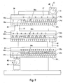
- FIG. 2 shows a cascade with three troughs 30, 31, 32 arranged one above the other drying sludge passes through a product entry 33 into an upper trough 30 upper trough are a screw conveyor 34a for conveying the introduced sludge and a padel shaft 35a is arranged one above the other for circulating the introduced sludge.
- the transport screw 34a With the help of the transport screw 34a, the introduced sludge becomes a trough discharge 36 of the upper trough 30 transported.
- the sludge is removed using the transport screw 34a and the paddle shaft 35a continuously circulated and mixed. Through contact the sludge is dried with the heated trough walls.
- the screw blades 37a of the transport screws 34a and the paddles grip 38a of the paddle shafts 35a at least partially one inside the other.
- the Transport screws 34a and the paddle shaft 35a comb through the screw vanes 37a and the paddles 38a.
- the layer thickness of the sludge in a space between the screw blades 37a and the paddles 38a compared to a trough with only one single conveyor screw essentially halved. This halving of the layer thickness leads to more effective heat transfer from the heated parts of the troughs to the drying mud.
- the sludge After passing through the trough discharge 36, the sludge reaches an upper intermediate section 41 and falls through it into a middle trough 31.
- the sludge In the middle Trough 31, the sludge is conveyed in one direction by means of the screw conveyor 34b, which is opposite to a conveying direction in the upper trough 30.
- a paddle wave 35b is used to circulate the sludge.
- Through a trough discharge 42 of the middle trough 30 and the sludge then passes through a lower connecting portion 43 into a lower one Trough 32.
- the sludge is again transported using the screw conveyor 34c promoted and in this way reaches a product discharge 44.
- a paddle shaft 35c supports the circulation of the sludge to be dried.
- the distance between adjacent paddles is paddle 38b on the paddle shaft 35b less than the distance between adjacent paddles of the paddles 38a on the paddle shaft 35a, so that the number of paddles 38b greater than the number of Paddle 38a is.
- the same statement applies in relation to the paddles 38c on the paddle shaft 35c and the paddle 38b on the paddle shaft 35b.
- Increasing the number of paddles in successive troughs has the advantage that particles of the dry matter contained in one of the Troughs were created under the influence of the paddle wave in the trough that followed Using a paddle shaft can be further crushed to the same length as the paddle shaft but has a higher number of paddles in the previous trough. To this The dry material is shredded piece by piece.
- the number and the Positioning of the paddles 38a, 38b and 38c on the incline of the transport screws 35a, 35b or 35c adapted so that combing the paddles 38a, 38b or 38c and the screw wing 37a, 37b and 37c is guaranteed.
- the product entry 33 and the product discharge 44 are made using an entry lock 45 or a discharge lock 46 opened and closed.
- a delivery space 47 can be closed airtight, which is between the product entry 33 and the product discharge 44 through the troughs 30, 31, 32 and the upper one and the lower connecting portion 41, 33 extends therethrough. This prevents that false air, in particular ambient air, enters the delivery chamber 47.
- In the funding room 47 is done by heating the troughs and optionally heating the conveyor screws 34a-34c and / or the paddle shafts 35a-35c a very high temperature, preferably about 300 ° C, generated to dry the sludge.
- the intrusion of bad air For example, from ambient air, has a cooling effect and is effective when drying the Sludge counterproductive.
- the airtight sealing of the delivery space 47 with the help of the entry lock 45 and the Discharge lock 46 also serves to improve safety when operating the device for drying mud.
- the sewage sludge drying produces fine dust. This fine dust is stored in troughs 30, 31, 32 and in the suction system 17 (see FIG. 1). The fine dust begins at around 120 ° C with the development of heat to oxidize. This can lead to dreaded and dangerous fine dust deflagrations and lead to plant fires. This is done with the help of the entry lock 47 and the discharge lock 46 thereby prevents no air in the troughs 30, 31, 32 and the suction system 17 arrives, so that only vapors, i.e. saturated steam is present. Thus the Safety of sewage sludge drying units significantly improved.
- the entry lock 45 can expediently be designed as a metering lock to the To be able to control the amount of sludge to be introduced.
- the suction system 17 can be compared to the Outside air and / or the delivery space 47 by suitable measures, e.g. Valves, locks or the like. Be insulated so that no false air can enter through the suction system.
- suitable measures e.g. Valves, locks or the like.
- the entry lock 45 and the discharge lock 46 for airtight Closing the delivery space 47 is also provided in a drying device can be, in which only a single screw is arranged in the troughs, as it is known from the prior art.
- the beneficial effect of airtight sealing of the delivery space 47 with the aid of the entry lock 45 and the discharge lock 46 also given in this case without restriction.
- a conveying space between product entry and product discharge with the help of an entry lock and a Discharge lock can be closed airtight.
- the product entry closed with the entry lock and the product discharge with the discharge lock his.
- FIG. 3 shows a side view with two cascades 60, 61, each with three troughs 62a, 63a, 64a and 62b, 63b, 64b.
- the cascades 60, 61 can, for example, the trough arrangement with the troughs 30, 31, 32 according to Figure 2 correspond.
- the one to be dried Sludge enters the respective cascade 60, 61 through a product entry 65a or 65b and is in the troughs 62a, 63a, 64a and 62b, 63b, 64b each with the help of a screw conveyor 66a, 66b and 66c and a further screw conveyor 67a, 67b and 67c.
- the sludge to be dried finally arrives in the respective cascade 60, 61 a product discharge 68a or 68b.
- a paddle shaft 70 or 71 for circulating and Crushing the sludge is arranged so that a central longitudinal axis of the Paddle shafts 70, 71 each parallel to a central longitudinal axis of the screw conveyor 66a or the further screw conveyor 67a.
- the paddle shafts 70, 71 are also arranged in a horizontal plane which lies above the horizontal plane in which the screw conveyor 66a and the further screw conveyor 67a are arranged.
- paddle 72, 73 of the paddle shafts 70, 71 mesh with one another with the screw blades 68 and 69, respectively when circulating and conveying the dry material.
- FIG. 3 With the aid of arrows A1 it is shown in FIG. 3 how the vapors are using a suction device 80 are sucked off via the evaporation surfaces 74.
- the Vapors of the two cascades 60, 61 passed in a common exhaust duct 75, which between the cascades is arranged.
- the exhaust duct 75 is with the help formed by channel components 77.
- the channel components 77 are mechanical Properties, in particular with regard to a material used and a material thickness and a profile design, designed so that a support structure by means of the channel components 77 is formed, on which the troughs 62a, 63a, 64a and 62b, 63b, 64b are arranged.
- the channel components 77 thus perform two very different functions: forming the exhaust air duct 75 for removing the vapors and forming a supporting structure for the troughs 62a, 63a, 64a and 62b, 63b, 64b. This saves material. Regardless of the specific training the troughs 62a, 63a, 64a or 62b, 63b, 64b and the circulation / drying components arranged therein, in particular the arrangement and design of the paddle shafts 70, 71, is a drying system with the help of the described construction of the channel components 77 created that, compared to known systems, those formed by means of the channel components 77, has multifunctional exhaust air duct 75.
- the two cascades 60, 61 can be operated independently of one another.
- the individual troughs each have an individual drive, which operates independently of at least the drive of the troughs of the other cascade can, as well as that the troughs of each cascade have a common drive, which can be operated independently of the drive of the other cascade.
- the drive of the screw conveyors of cascades connected in series in a cascade can be coupled so that the conveying direction in the corresponding troughs simultaneously is reversed. It can also be provided that the troughs 30, 31, 32 (see FIG. 2) or 62a, 63a, 64 and / or 62b, 63b, 64 (see FIG. 3) each have their own separate drives.
- the conveying direction of all transport screws can be selected reversed in a cascade or just the conveying direction of screw conveyors in part of the troughs, for example only in one trough, during the conveying direction remains unchanged for the other troughs.
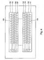
- Figure 4 shows a schematic representation of two troughs arranged side by side 100, 101 with two transport screws 102, 103 and 104, 105 from above.
- two transport screws 102, 103 and 104, 105 can be, for example, the troughs 62a and 62b and the transport screw 66a and the further transport screw 67a act.
- Wings 106, 107 and 108, 109 of the two Transport screws 102, 103 and 104, 105 mesh with each other when turning, so that the Layer thickness of the dry material is reduced.
Landscapes
- Engineering & Computer Science (AREA)
- Mechanical Engineering (AREA)
- Life Sciences & Earth Sciences (AREA)
- Hydrology & Water Resources (AREA)
- Environmental & Geological Engineering (AREA)
- Water Supply & Treatment (AREA)
- Chemical & Material Sciences (AREA)
- Organic Chemistry (AREA)
- General Engineering & Computer Science (AREA)
- Treatment Of Sludge (AREA)
- Drying Of Solid Materials (AREA)
Abstract
Description
- Figur 1
- eine schematische Darstellung einer Trocknungsanlage für Schlamm;
- Figur 2
- eine schematische Darstellung einer Kaskade einer Trocknungsanlage von der Seite;
- Figur 3
- eine schematische Darstellung von zwei nebeneinander angeordneten Kaskaden einer Trocknungsanlage; und
- Figur 4
- eine schematische Darstellung von zwei nebeneinander angeordneten Trögen in Draufsicht.
Claims (21)
- Vorrichtung zum Trocknen von Schlamm, insbesondere Klär- oder Faulschlamm, mit einer Transporteinrichtung zum Fördern des Schlamms zwischen einem Produkteintrag (65a) und einem Produktaustrag (68a) und einer Heizeinrichtung zum Aufheizen des Schlamms in der Transporteinrichtung, wobei die Transporteinrichtung wenigstens einen Trog (62a) umfaßt und wobei in einem Innenraum des wenigstens einen Trogs (62a) eine Transportschnecke (66a) mit Flügeln (68) zum Fördern des Schlamms angeordnet ist, dadurch gekennzeichnet, daß im Innenraum des wenigstens einen Trogs (62a) wenigstens eine Paddelwelle (70) mit Paddeln (72) zum Umwälzen des Schlamms vorgesehen ist.
- Vorrichtung nach Anspruch 1, dadurch gekennzeichnet, daß die Paddelwelle (70) oberhalb der Transportschnecke (66a) angeordnet ist.
- Vorrichtung nach Anspruch 2, dadurch gekennzeichnet, daß beim Umwälzen des Schlamms die Paddel (72) der Paddelwelle (70) mit den Flügeln (68) der Transportschnecke (66a) ineinander greifen.
- Vorrichtung nach einem der vorangehenden Ansprüche, dadurch gekennzeichnet, daß neben der Transportschnecke (66a) wenigstens eine weitere Transportschnecke (67a) vorgesehen ist, daß die Transportschnecke (66a) und die wenigstens eine weitere Transportschnecke (67a) in einer horizontalen Ebene nebeneinander angeordnet sind und daß oberhalb der wenigstens einen weiteren Transportschnecke (67a) zumindest eine weitere Paddelwelle (71) mit Paddeln (73) zum Umwälzen des Schlamms angeordnet ist.
- Vorrichtung nach Anspruch 4, dadurch gekennzeichnet, daß beim Umwälzen des Schlamms die Paddel (72) der einen Paddelwelle (70) und die Paddel (73) der zumindest einen weiteren Paddelwelle (71) ineinander greifen.
- Vorrichtung nach Anspruch 4 oder 5, dadurch gekennzeichnet, daß die Paddelwelle (70) oberhalb der Transportschnecke (66a) und die zumindest eine weitere Paddelwelle (71) oberhalb der wenigstens einen weiteren Transportschnecke (67a) so angeordnet sind, daß eine Mittelachse der Paddelwelle (70) in Längsrichtung und eine Mittelachse der Transportschnecke (66a) in Längsrichtung sowie eine Mittelachse der zumindest einen weiteren Paddelwelle (71) in Längsrichtung und eine Mittelachse der wenigstens einen weiteren Transportschnecke (67a) in Längsrichtung jeweils im wesentlichen in einer vertikalen Ebene liegen.
- Vorrichtung nach einem der Ansprüche 4 bis 6, dadurch gekennzeichnet, daß die Paddel (73) der zumindest einen weiteren Paddelwelle (71) und die Flügel (69) der wenigstens einen weiteren Transportschnecke (67a) beim Umwälzen des Schlamms jeweils ineinander kämmen.
- Vorrichtung nach einem der Ansprüche 4 bis 7, dadurch gekennzeichnet, daß die Transportschnecke (66a) und/oder die wenigstens eine weitere Transportschnecke (67a) jeweils als eine Schneckenwelle und die Flügel (68) bzw. (69) jeweils als Schneckenflügel ausgebildet sind.
- Vorrichtung nach einem der Ansprüche 4 bis 8, dadurch gekennzeichnet, daß die Transportschnecke (66a) und die wenigstens eine weitere Transportschnecke (67a) mechanisch miteinander gekoppelt sind.
- Vorrichtung nach Anspruch 9, dadurch gekennzeichnet, daß die Transportschnecke (66a) und die wenigstens eine weitere Transportschnecke (67a) so miteinander gekoppelt sind, daß die Transportschnecke (66a) und die wenigstens eine weitere Transportschnecke (67a) mit einer gemeinsamen Drehgeschwindigkeit drehbar sind.
- Vorrichtung nach Anspruch 9 oder 10, dadurch gekennzeichnet, daß die Transportschnecke (66a) und die wenigstens eine weitere Transportschnecke (67a) so miteinander gekoppelt sind, daß eine Drehrichtung der Transportschnecke (66a) entgegengesetzt zu einer Drehrichtung der wenigstens einen weiteren Transportschnecke (67a) ausgebildet ist.
- Vorrichtung nach einem der Ansprüche 9 bis 11, dadurch gekennzeichnet, daß die Transportschnecke (66a) und die wenigstens eine weitere Transportschnecke (67a) mittels einer Zahnradverbindung miteinander gekoppelt sind.
- Vorrichtung nach Anspruch 12, dadurch gekennzeichnet, daß die Zahnradverbindung mit Hilfe eines Zahnradpaares ausgebildet ist, wobei das Zahnradpaar ein Übersetzungsverhältnis von 1:1 aufweist.
- Vorrichtung nach einem der vorangehenden Ansprüche, dadurch gekennzeichnet, daß die Transportschnecke (66a) mit einem Aufsteckgetriebe zum Antreiben einer Drehbewegung der Transportschnecke (66a) kraftschlüssig verbunden ist.
- Vorrichtung nach einem der vorangehenden Ansprüche, dadurch gekennzeichnet, daß die Drehrichtung der Transportschnecke (66a) und/oder die Drehrichtung der wenigstens einen weiteren Transportschnecke (67a) mindestens kurzzeitig jeweils umkehrbar sind, so daß die Förderung des Schlamms wenigstens teilweise umgekehrt wird.
- Vorrichtung nach einem der vorangehenden Ansprüche, dadurch gekennzeichnet, daß die Flügel (68) der Transportschnecke (66a) und/oder die Flügel (69) der wenigstens einen weiteren Transportschnecke (67a) beheizt sind.
- Vorrichtung nach Anspruch 16, dadurch gekennzeichnet, daß die Flügel (68) der Transportschnecke (66a) und/oder die Flügel (69) der wenigstens einen weiteren Transportschnecke (67a) wenigstens in Teilbereichen jeweils doppelwandig ausgebildet sind, so daß die Flügel (68) der Transportschnecke (66a) und/oder die Flügel (69) der wenigstens einen weiteren Transportschnecke (67a) zum Beheizen von einem Medium durchströmt werden können.
- Vorrichtung nach einem der vorangehenden Ansprüche, dadurch gekennzeichnet, daß der wenigstens eine Trog (62a) thermisch isoliert ist.
- Vorrichtung nach einem der vorangehenden Ansprüche, dadurch gekennzeichnet, daß der Innenraum des wenigstens einen Trogs (62a) gegenüber einer Umgebung des Trogs (62a) luftdicht abgeschlossen ist.
- Vorrichtung nach einem der vorangehenden Ansprüche, dadurch gekennzeichnet, daß die Paddelwelle (70) mechanisch an die Transportschnecke (66a) gekoppelt ist.
- Vorrichtung nach einem der Ansprüche 4 bis 20, dadurch gekennzeichnet, daß die zumindest eine weitere Paddelwelle (71) an die Paddelwelle (70) mechanisch gekoppelt ist, so daß die zumindest eine weitere Paddelwelle (71) und die Paddelwelle (70) gemeinsam drehbar sind.
Applications Claiming Priority (2)
| Application Number | Priority Date | Filing Date | Title |
|---|---|---|---|
| DE10152033 | 2001-10-23 | ||
| DE10152033A DE10152033B4 (de) | 2001-10-23 | 2001-10-23 | Vorrichtung zum Trocknen von Schlamm |
Publications (3)
| Publication Number | Publication Date |
|---|---|
| EP1306352A2 true EP1306352A2 (de) | 2003-05-02 |
| EP1306352A3 EP1306352A3 (de) | 2003-11-26 |
| EP1306352B1 EP1306352B1 (de) | 2007-01-03 |
Family
ID=7703278
Family Applications (1)
| Application Number | Title | Priority Date | Filing Date |
|---|---|---|---|
| EP02023807A Expired - Lifetime EP1306352B1 (de) | 2001-10-23 | 2002-10-23 | Vorrichtung zum Trocknen von Schlamm mit einer Heizeinrichtung in einer Transporteinrichtung |
Country Status (3)
| Country | Link |
|---|---|
| EP (1) | EP1306352B1 (de) |
| AT (1) | ATE350346T1 (de) |
| DE (2) | DE10152033B4 (de) |
Cited By (10)
| Publication number | Priority date | Publication date | Assignee | Title |
|---|---|---|---|---|
| EP2261587A1 (de) * | 2009-06-13 | 2010-12-15 | EFU Engineering für Umwelttechnik GmbH | Anlage zur Trocknung von Klärschlamm |
| FR2953006A1 (fr) * | 2009-11-24 | 2011-05-27 | Vinci Environnement | Installation et procede de sechage de produit charge en eau |
| WO2012053147A1 (ja) * | 2010-10-20 | 2012-04-26 | 睦和興業株式会社 | 乾燥・炭化装置及びその方法 |
| CN102583945A (zh) * | 2012-01-13 | 2012-07-18 | 哈尔滨工业大学 | 污泥多级干化器、流化床焚烧处理装置及方法 |
| DE102013100595A1 (de) | 2012-01-20 | 2013-08-29 | Peter Damian | System zum Trocknen von Schlamm |
| JP2014234948A (ja) * | 2013-06-03 | 2014-12-15 | 睦和興業株式会社 | 乾燥炭化装置及びその方法 |
| CN104549113A (zh) * | 2013-10-22 | 2015-04-29 | 上海金匙环保科技股份有限公司 | 具有在线清扫机构的干燥设备 |
| CN106623363A (zh) * | 2016-12-24 | 2017-05-10 | 无锡明珠增压器制造有限公司 | 废塑料用混合装置 |
| CN110342771A (zh) * | 2019-07-28 | 2019-10-18 | 梁秀宜 | 一种自动进料型污泥处理设备 |
| CN113856281A (zh) * | 2021-11-24 | 2021-12-31 | 翟枫 | 一种水利工程用淤泥处理装置 |
Families Citing this family (2)
| Publication number | Priority date | Publication date | Assignee | Title |
|---|---|---|---|---|
| CN107560370A (zh) * | 2017-07-31 | 2018-01-09 | 兰溪市捷喜食品加工技术有限公司 | 一种搅拌式高压快速干燥机 |
| CN110953867A (zh) * | 2019-11-20 | 2020-04-03 | 芜湖应天光电科技有限责任公司 | 一种用于电子工业金属粉末烘干机的烘干筒 |
Family Cites Families (5)
| Publication number | Priority date | Publication date | Assignee | Title |
|---|---|---|---|---|
| US4872998A (en) * | 1988-06-10 | 1989-10-10 | Bio Gro Systems, Inc. | Apparatus and process for forming uniform, pelletizable sludge product |
| JPH01315399A (ja) * | 1988-06-13 | 1989-12-20 | Takuma Co Ltd | 汚泥乾燥装置 |
| DE8816171U1 (de) * | 1988-12-29 | 1990-04-26 | Frühbis, Hans, 6732 Edenkoben | Vorrichtung zum Trocknen von Schlamm |
| DE4230679A1 (de) * | 1992-09-14 | 1994-03-17 | Bayer Ag | Verfahren zur kontinuierlichen Klärschlammtrocknung |
| DE10002535C2 (de) * | 1999-12-20 | 2002-03-14 | Faten Hasenkopf | Vorrichtung zum Trocknen von Schlamm |
-
2001
- 2001-10-23 DE DE10152033A patent/DE10152033B4/de not_active Expired - Fee Related
-
2002
- 2002-10-23 DE DE50209148T patent/DE50209148D1/de not_active Expired - Fee Related
- 2002-10-23 EP EP02023807A patent/EP1306352B1/de not_active Expired - Lifetime
- 2002-10-23 AT AT02023807T patent/ATE350346T1/de not_active IP Right Cessation
Cited By (20)
| Publication number | Priority date | Publication date | Assignee | Title |
|---|---|---|---|---|
| EP2261587A1 (de) * | 2009-06-13 | 2010-12-15 | EFU Engineering für Umwelttechnik GmbH | Anlage zur Trocknung von Klärschlamm |
| FR2953006A1 (fr) * | 2009-11-24 | 2011-05-27 | Vinci Environnement | Installation et procede de sechage de produit charge en eau |
| WO2011064471A1 (fr) * | 2009-11-24 | 2011-06-03 | Vinci Environnement | Procede de sechage de produit charge en eau |
| CN103154651A (zh) * | 2010-10-20 | 2013-06-12 | 睦和兴业株式会社 | 干燥/炭化装置及其方法 |
| JP2012087988A (ja) * | 2010-10-20 | 2012-05-10 | Mutsuwa Kogyo Kk | 乾燥・炭化装置 |
| RU2570993C2 (ru) * | 2010-10-20 | 2015-12-20 | Мицува Когио Кабусики Кайся | Устройство для сушки/коксования и способ его работы |
| AU2011319390B2 (en) * | 2010-10-20 | 2014-12-18 | Mutsuwa Kogyo Kabushiki Kaisha | Drying/carbonizing device and method thereof |
| WO2012053147A1 (ja) * | 2010-10-20 | 2012-04-26 | 睦和興業株式会社 | 乾燥・炭化装置及びその方法 |
| US9279614B2 (en) | 2010-10-20 | 2016-03-08 | Mutsuwa Kogyo Kabushiki Kaisha | Drying/carbonizing device and method thereof |
| CN103154651B (zh) * | 2010-10-20 | 2015-05-13 | 睦和兴业株式会社 | 干燥/炭化装置及其方法 |
| CN102583945A (zh) * | 2012-01-13 | 2012-07-18 | 哈尔滨工业大学 | 污泥多级干化器、流化床焚烧处理装置及方法 |
| DE102013100595A1 (de) | 2012-01-20 | 2013-08-29 | Peter Damian | System zum Trocknen von Schlamm |
| JP2014234948A (ja) * | 2013-06-03 | 2014-12-15 | 睦和興業株式会社 | 乾燥炭化装置及びその方法 |
| CN104549113A (zh) * | 2013-10-22 | 2015-04-29 | 上海金匙环保科技股份有限公司 | 具有在线清扫机构的干燥设备 |
| WO2015058446A1 (zh) * | 2013-10-22 | 2015-04-30 | 上海金匙环保科技股份有限公司 | 具有在线清扫机构的干燥设备 |
| CN104549113B (zh) * | 2013-10-22 | 2016-08-17 | 上海金匙环保科技股份有限公司 | 具有在线清扫机构的干燥设备 |
| CN106623363A (zh) * | 2016-12-24 | 2017-05-10 | 无锡明珠增压器制造有限公司 | 废塑料用混合装置 |
| CN110342771A (zh) * | 2019-07-28 | 2019-10-18 | 梁秀宜 | 一种自动进料型污泥处理设备 |
| CN110342771B (zh) * | 2019-07-28 | 2022-08-26 | 梁秀宜 | 一种自动进料型污泥处理设备 |
| CN113856281A (zh) * | 2021-11-24 | 2021-12-31 | 翟枫 | 一种水利工程用淤泥处理装置 |
Also Published As
| Publication number | Publication date |
|---|---|
| EP1306352B1 (de) | 2007-01-03 |
| ATE350346T1 (de) | 2007-01-15 |
| DE10152033B4 (de) | 2004-03-04 |
| DE10152033A1 (de) | 2003-06-12 |
| DE50209148D1 (de) | 2007-02-15 |
| EP1306352A3 (de) | 2003-11-26 |
Similar Documents
| Publication | Publication Date | Title |
|---|---|---|
| EP1306352B1 (de) | Vorrichtung zum Trocknen von Schlamm mit einer Heizeinrichtung in einer Transporteinrichtung | |
| DE3010966A1 (de) | Vorrichtung zum fluessigkeitsentzug durch waerme- bzw. kuehlbehandlung bzw. zum kristallisieren ggf. unter vakuum | |
| EP0624124A1 (de) | Mehrwellige kontinuierlich arbeitende misch- und knetmaschine für plastifizierbare massen. | |
| WO1995013181A1 (de) | Mehrwellige kontinuierlich arbeitende mischmaschine für plastifizierbare massen | |
| EP0588160B1 (de) | Verfahren und Vorrichtung zur Behandlung von Abfallstoffen, insbesondere von organischen Gastronomieabfällen | |
| EP0167939B1 (de) | Vorrichtung zur Behandlung eines Gutes zur Trennung einer flüssigen Phase von einer festen Phase | |
| DE1778559A1 (de) | Verfahren zur Zerkleinerung von koernigem oder stueckigem Gut | |
| DE69004189T2 (de) | Anordnungen zur behandlung menschlichen oder tierischen abfalls mittels mikrowellen. | |
| DE2550142C2 (de) | ||
| EP2326900A2 (de) | Verfahren und vorrichtung zum trocknen von biomasse | |
| EP2985339B1 (de) | Gärrest-Konditionierer und Verfahren zur Konditionierung von Gärresten | |
| DE10002535C2 (de) | Vorrichtung zum Trocknen von Schlamm | |
| EP1319632A1 (de) | Verfahren und Vorrichtung zur Trocknung von Schlamm, insbesondere von Abwasserschlamm | |
| DE602005000934T2 (de) | Anlage zur Trocknung von pastösen Produkten und Verwendung derselben. | |
| DE68912430T2 (de) | Verfahren und Vorrichtung zur Trocknung von organischen Abfällen. | |
| EP0379121A1 (de) | Verfahren und Anlage zur Dekontaminierung von Schadstoffe enthaltendem Erdreich,Schlämmen, Bauschutt oder dergleichen | |
| DE20022948U1 (de) | Vorrichtung zum Trocknen von Schlamm | |
| DE102009051381A1 (de) | Trockner zum Behandeln von Gartenabfall | |
| DE20122078U1 (de) | Vorrichtung zum Trocknen von Schlamm | |
| DE20022815U1 (de) | Vorrichtung zum Trocknen von Schlamm | |
| EP0611937A1 (de) | Mischer-Trockner | |
| CH664928A5 (de) | Verfahren und schneckenpresse zum verdichten und entwaessern von festmaterial. | |
| DE102019133787A1 (de) | Rotierend antreibbare Mahlkörpermühle zur Gewinnung von Polyisopren und/oder anderen apolaren Werkstoffen | |
| DE2548251A1 (de) | Vorrichtung zum fixieren radioaktiver abfaelle | |
| DE102015007912A1 (de) | Vorrichtung und Verfahren zum Behandeln von insbesondere kleinstückigem Schüttgut |
Legal Events
| Date | Code | Title | Description |
|---|---|---|---|
| PUAI | Public reference made under article 153(3) epc to a published international application that has entered the european phase |
Free format text: ORIGINAL CODE: 0009012 |
|
| AK | Designated contracting states |
Designated state(s): AT BE BG CH CY CZ DE DK EE ES FI FR GB GR IE IT LI LU MC NL PT SE SK TR |
|
| AX | Request for extension of the european patent |
Extension state: AL LT LV MK RO SI |
|
| PUAL | Search report despatched |
Free format text: ORIGINAL CODE: 0009013 |
|
| AK | Designated contracting states |
Kind code of ref document: A3 Designated state(s): AT BE BG CH CY CZ DE DK EE ES FI FR GB GR IE IT LI LU MC NL PT SE SK TR |
|
| AX | Request for extension of the european patent |
Extension state: AL LT LV MK RO SI |
|
| 17P | Request for examination filed |
Effective date: 20031128 |
|
| RAP1 | Party data changed (applicant data changed or rights of an application transferred) |
Owner name: ANRO ANLAGEN- UND ROHRLEITUNGSBAU GMBH |
|
| AKX | Designation fees paid |
Designated state(s): AT BE BG CH CY CZ DE DK EE ES FI FR GB GR IE IT LI LU MC NL PT SE SK TR |
|
| GRAP | Despatch of communication of intention to grant a patent |
Free format text: ORIGINAL CODE: EPIDOSNIGR1 |
|
| RAP1 | Party data changed (applicant data changed or rights of an application transferred) |
Owner name: VTA VERFAHRENSTECHNISCHE ANLAGEN GMBH |
|
| GRAS | Grant fee paid |
Free format text: ORIGINAL CODE: EPIDOSNIGR3 |
|
| GRAA | (expected) grant |
Free format text: ORIGINAL CODE: 0009210 |
|
| AK | Designated contracting states |
Kind code of ref document: B1 Designated state(s): AT BE BG CH CY CZ DE DK EE ES FI FR GB GR IE IT LI LU MC NL PT SE SK TR |
|
| PG25 | Lapsed in a contracting state [announced via postgrant information from national office to epo] |
Ref country code: IE Free format text: LAPSE BECAUSE OF FAILURE TO SUBMIT A TRANSLATION OF THE DESCRIPTION OR TO PAY THE FEE WITHIN THE PRESCRIBED TIME-LIMIT Effective date: 20070103 Ref country code: NL Free format text: LAPSE BECAUSE OF FAILURE TO SUBMIT A TRANSLATION OF THE DESCRIPTION OR TO PAY THE FEE WITHIN THE PRESCRIBED TIME-LIMIT Effective date: 20070103 Ref country code: FI Free format text: LAPSE BECAUSE OF FAILURE TO SUBMIT A TRANSLATION OF THE DESCRIPTION OR TO PAY THE FEE WITHIN THE PRESCRIBED TIME-LIMIT Effective date: 20070103 Ref country code: DK Free format text: LAPSE BECAUSE OF FAILURE TO SUBMIT A TRANSLATION OF THE DESCRIPTION OR TO PAY THE FEE WITHIN THE PRESCRIBED TIME-LIMIT Effective date: 20070103 |
|
| REG | Reference to a national code |
Ref country code: GB Ref legal event code: FG4D Free format text: NOT ENGLISH |
|
| REF | Corresponds to: |
Ref document number: 50209148 Country of ref document: DE Date of ref document: 20070215 Kind code of ref document: P |
|
| REG | Reference to a national code |
Ref country code: IE Ref legal event code: FG4D Free format text: LANGUAGE OF EP DOCUMENT: GERMAN |
|
| PG25 | Lapsed in a contracting state [announced via postgrant information from national office to epo] |
Ref country code: SE Free format text: LAPSE BECAUSE OF FAILURE TO SUBMIT A TRANSLATION OF THE DESCRIPTION OR TO PAY THE FEE WITHIN THE PRESCRIBED TIME-LIMIT Effective date: 20070403 |
|
| PG25 | Lapsed in a contracting state [announced via postgrant information from national office to epo] |
Ref country code: BG Free format text: LAPSE BECAUSE OF THE APPLICANT RENOUNCES Effective date: 20070404 |
|
| PG25 | Lapsed in a contracting state [announced via postgrant information from national office to epo] |
Ref country code: ES Free format text: LAPSE BECAUSE OF FAILURE TO SUBMIT A TRANSLATION OF THE DESCRIPTION OR TO PAY THE FEE WITHIN THE PRESCRIBED TIME-LIMIT Effective date: 20070414 |
|
| PG25 | Lapsed in a contracting state [announced via postgrant information from national office to epo] |
Ref country code: PT Free format text: LAPSE BECAUSE OF FAILURE TO SUBMIT A TRANSLATION OF THE DESCRIPTION OR TO PAY THE FEE WITHIN THE PRESCRIBED TIME-LIMIT Effective date: 20070604 |
|
| NLV1 | Nl: lapsed or annulled due to failure to fulfill the requirements of art. 29p and 29m of the patents act | ||
| GBV | Gb: ep patent (uk) treated as always having been void in accordance with gb section 77(7)/1977 [no translation filed] |
Effective date: 20070103 |
|
| REG | Reference to a national code |
Ref country code: IE Ref legal event code: FD4D |
|
| EN | Fr: translation not filed | ||
| PLBE | No opposition filed within time limit |
Free format text: ORIGINAL CODE: 0009261 |
|
| STAA | Information on the status of an ep patent application or granted ep patent |
Free format text: STATUS: NO OPPOSITION FILED WITHIN TIME LIMIT |
|
| PG25 | Lapsed in a contracting state [announced via postgrant information from national office to epo] |
Ref country code: SK Free format text: LAPSE BECAUSE OF FAILURE TO SUBMIT A TRANSLATION OF THE DESCRIPTION OR TO PAY THE FEE WITHIN THE PRESCRIBED TIME-LIMIT Effective date: 20070103 Ref country code: GB Free format text: LAPSE BECAUSE OF FAILURE TO SUBMIT A TRANSLATION OF THE DESCRIPTION OR TO PAY THE FEE WITHIN THE PRESCRIBED TIME-LIMIT Effective date: 20070103 |
|
| 26N | No opposition filed |
Effective date: 20071005 |
|
| PG25 | Lapsed in a contracting state [announced via postgrant information from national office to epo] |
Ref country code: CZ Free format text: LAPSE BECAUSE OF FAILURE TO SUBMIT A TRANSLATION OF THE DESCRIPTION OR TO PAY THE FEE WITHIN THE PRESCRIBED TIME-LIMIT Effective date: 20070103 |
|
| BERE | Be: lapsed |
Owner name: VTA VERFAHRENSTECHNISCHE ANLAGEN G.M.B.H. Effective date: 20071031 |
|
| PG25 | Lapsed in a contracting state [announced via postgrant information from national office to epo] |
Ref country code: FR Free format text: LAPSE BECAUSE OF FAILURE TO SUBMIT A TRANSLATION OF THE DESCRIPTION OR TO PAY THE FEE WITHIN THE PRESCRIBED TIME-LIMIT Effective date: 20070824 Ref country code: IT Free format text: LAPSE BECAUSE OF FAILURE TO SUBMIT A TRANSLATION OF THE DESCRIPTION OR TO PAY THE FEE WITHIN THE PRESCRIBED TIME-LIMIT Effective date: 20070103 Ref country code: GR Free format text: LAPSE BECAUSE OF FAILURE TO SUBMIT A TRANSLATION OF THE DESCRIPTION OR TO PAY THE FEE WITHIN THE PRESCRIBED TIME-LIMIT Effective date: 20070404 |
|
| PG25 | Lapsed in a contracting state [announced via postgrant information from national office to epo] |
Ref country code: MC Free format text: LAPSE BECAUSE OF NON-PAYMENT OF DUE FEES Effective date: 20071031 |
|
| REG | Reference to a national code |
Ref country code: CH Ref legal event code: PL |
|
| PG25 | Lapsed in a contracting state [announced via postgrant information from national office to epo] |
Ref country code: LI Free format text: LAPSE BECAUSE OF NON-PAYMENT OF DUE FEES Effective date: 20071031 Ref country code: CH Free format text: LAPSE BECAUSE OF NON-PAYMENT OF DUE FEES Effective date: 20071031 |
|
| PG25 | Lapsed in a contracting state [announced via postgrant information from national office to epo] |
Ref country code: BE Free format text: LAPSE BECAUSE OF NON-PAYMENT OF DUE FEES Effective date: 20071031 |
|
| PG25 | Lapsed in a contracting state [announced via postgrant information from national office to epo] |
Ref country code: FR Free format text: LAPSE BECAUSE OF FAILURE TO SUBMIT A TRANSLATION OF THE DESCRIPTION OR TO PAY THE FEE WITHIN THE PRESCRIBED TIME-LIMIT Effective date: 20070103 |
|
| PG25 | Lapsed in a contracting state [announced via postgrant information from national office to epo] |
Ref country code: EE Free format text: LAPSE BECAUSE OF FAILURE TO SUBMIT A TRANSLATION OF THE DESCRIPTION OR TO PAY THE FEE WITHIN THE PRESCRIBED TIME-LIMIT Effective date: 20070103 |
|
| PGFP | Annual fee paid to national office [announced via postgrant information from national office to epo] |
Ref country code: DE Payment date: 20081022 Year of fee payment: 7 |
|
| PG25 | Lapsed in a contracting state [announced via postgrant information from national office to epo] |
Ref country code: AT Free format text: LAPSE BECAUSE OF NON-PAYMENT OF DUE FEES Effective date: 20071023 |
|
| PG25 | Lapsed in a contracting state [announced via postgrant information from national office to epo] |
Ref country code: CY Free format text: LAPSE BECAUSE OF FAILURE TO SUBMIT A TRANSLATION OF THE DESCRIPTION OR TO PAY THE FEE WITHIN THE PRESCRIBED TIME-LIMIT Effective date: 20070103 |
|
| PG25 | Lapsed in a contracting state [announced via postgrant information from national office to epo] |
Ref country code: LU Free format text: LAPSE BECAUSE OF NON-PAYMENT OF DUE FEES Effective date: 20071023 |
|
| PG25 | Lapsed in a contracting state [announced via postgrant information from national office to epo] |
Ref country code: TR Free format text: LAPSE BECAUSE OF FAILURE TO SUBMIT A TRANSLATION OF THE DESCRIPTION OR TO PAY THE FEE WITHIN THE PRESCRIBED TIME-LIMIT Effective date: 20070103 |
|
| PG25 | Lapsed in a contracting state [announced via postgrant information from national office to epo] |
Ref country code: DE Free format text: LAPSE BECAUSE OF NON-PAYMENT OF DUE FEES Effective date: 20100501 |