EP1306352A2 - Assembly for drying sludge comprising a heating appliance within a conveying device - Google Patents
Assembly for drying sludge comprising a heating appliance within a conveying device Download PDFInfo
- Publication number
- EP1306352A2 EP1306352A2 EP02023807A EP02023807A EP1306352A2 EP 1306352 A2 EP1306352 A2 EP 1306352A2 EP 02023807 A EP02023807 A EP 02023807A EP 02023807 A EP02023807 A EP 02023807A EP 1306352 A2 EP1306352 A2 EP 1306352A2
- Authority
- EP
- European Patent Office
- Prior art keywords
- screw
- sludge
- transport
- paddle shaft
- transport screw
- Prior art date
- Legal status (The legal status is an assumption and is not a legal conclusion. Google has not performed a legal analysis and makes no representation as to the accuracy of the status listed.)
- Granted
Links
Images


Classifications
-
- C—CHEMISTRY; METALLURGY
- C02—TREATMENT OF WATER, WASTE WATER, SEWAGE, OR SLUDGE
- C02F—TREATMENT OF WATER, WASTE WATER, SEWAGE, OR SLUDGE
- C02F11/00—Treatment of sludge; Devices therefor
- C02F11/12—Treatment of sludge; Devices therefor by de-watering, drying or thickening
- C02F11/121—Treatment of sludge; Devices therefor by de-watering, drying or thickening by mechanical de-watering
- C02F11/125—Treatment of sludge; Devices therefor by de-watering, drying or thickening by mechanical de-watering using screw filters
-
- C—CHEMISTRY; METALLURGY
- C02—TREATMENT OF WATER, WASTE WATER, SEWAGE, OR SLUDGE
- C02F—TREATMENT OF WATER, WASTE WATER, SEWAGE, OR SLUDGE
- C02F11/00—Treatment of sludge; Devices therefor
- C02F11/12—Treatment of sludge; Devices therefor by de-watering, drying or thickening
- C02F11/13—Treatment of sludge; Devices therefor by de-watering, drying or thickening by heating
-
- F—MECHANICAL ENGINEERING; LIGHTING; HEATING; WEAPONS; BLASTING
- F26—DRYING
- F26B—DRYING SOLID MATERIALS OR OBJECTS BY REMOVING LIQUID THEREFROM
- F26B17/00—Machines or apparatus for drying materials in loose, plastic, or fluidised form, e.g. granules, staple fibres, with progressive movement
- F26B17/18—Machines or apparatus for drying materials in loose, plastic, or fluidised form, e.g. granules, staple fibres, with progressive movement with movement performed by rotating helical blades or other rotary conveyors which may be heated moving materials in stationary chambers, e.g. troughs
- F26B17/20—Machines or apparatus for drying materials in loose, plastic, or fluidised form, e.g. granules, staple fibres, with progressive movement with movement performed by rotating helical blades or other rotary conveyors which may be heated moving materials in stationary chambers, e.g. troughs the axis of rotation being horizontal or slightly inclined
- F26B17/205—Machines or apparatus for drying materials in loose, plastic, or fluidised form, e.g. granules, staple fibres, with progressive movement with movement performed by rotating helical blades or other rotary conveyors which may be heated moving materials in stationary chambers, e.g. troughs the axis of rotation being horizontal or slightly inclined with multiple chambers, e.g. troughs, in superimposed arrangement
-
- F—MECHANICAL ENGINEERING; LIGHTING; HEATING; WEAPONS; BLASTING
- F26—DRYING
- F26B—DRYING SOLID MATERIALS OR OBJECTS BY REMOVING LIQUID THEREFROM
- F26B2200/00—Drying processes and machines for solid materials characterised by the specific requirements of the drying goods
- F26B2200/18—Sludges, e.g. sewage, waste, industrial processes, cooling towers
Definitions
- the invention relates to a device for drying sludge, in particular sewage or Digested sludge, with a transport device for conveying the sludge between one Product entry and a product discharge, and a heating device for heating the Sludge in the transport device, wherein the transport device at least one Includes trough, and wherein in an interior of the at least one trough a conveyor screw is arranged with wings for circulating and conveying the sludge.
- Devices of this type are used to treat the sewage or digested sludge occurring in sewage treatment plants prepare for landfilling with a high pollutant load and high water content. Contaminated soil, such as after a chemical accident, a garbage accident or the like can be treated in such a device become.
- the sludge to be dried which was previously used, for example, as part of a drainage can be treated, is introduced via the product entry in a trough.
- a worm shaft is arranged in the trough Promotes mud.
- several troughs are in a cascade arranged one above the other.
- the sludge to be dried passes along the cascade from the Product entry for a product discharge.
- the mud in each of the troughs promoted from a trough entry to a trough discharge.
- From the trough discharge of a parent The sludge enters the trough in a trough below.
- An intermediate section is formed for troughs for guiding the sludge.
- both the troughs and the screw conveyors heated so that the sludge is heated and water components evaporate.
- To this Purpose are double-walled trough walls so that the trough walls heat from one Medium, especially oil can be flowed through.
- a Shaft of the screw conveyor is also double-walled, so that the shaft of can flow through the heated medium.
- each of the troughs is connected to the suction device.
- the object of the present form is to provide an improved device as described in the introduction To create species with an increased efficiency in terms of sludge drying.
- the invention also has the advantage that a much better mixing of the sludge to be dried takes place. To this In this way, new dry goods parts are brought into contact with the heating device and thereby dried.
- the continuous mixing of the sludge leads to particles of the sludge, which are initially surrounded by other particles of the sludge so that not with the heated surfaces, e.g. heated troughs or snail wings, in contact occur, are exposed so that these particles can be dried.
- the continuous circulation using the paddle shaft prevents the formation of larger clumps in the troughs, which reduce the effectiveness of the drying process.
- An expedient development of the invention provides that the paddle shaft above the Transport screw is arranged. As a result, the cross section of the troughs is transverse to the longitudinal direction the transport screw is kept as low as possible. This has the advantage that a The smallest possible evaporation area is reached, which is in connection with the design of Suction devices for sucking off the vapors formed during the drying of the sludge is appropriate.
- paddle waves provide an expedient embodiment the invention that when the sludge is circulated, the paddles of a paddle shaft and the paddles of the at least one further paddle shaft interlock.
- the invention particularly expediently designed that the paddle shaft above the screw conveyor and the at least one further paddle shaft above the at least one further screw conveyor are arranged so that a central axis of the Paddle shaft in the longitudinal direction and a central axis of the screw conveyor in the longitudinal direction and a central axis of the at least one further paddle shaft in the longitudinal direction and a Central axis of the at least one further screw conveyor in the longitudinal direction in each case lie essentially in a vertical plane.
- the paddles of the at least one further paddle shaft and the wings of the at least one comb each other auger while circulating the sludge can additionally be provided that the paddles of the at least one further paddle shaft and the wings of the at least one comb each other auger while circulating the sludge. This significantly reduces the thickness of lumps of the dry material, for example by half.
- the transport screw and / or the at least one further screw conveyor each as a worm shaft are trained, creating a mechanically stable and high stress sufficient conveying screw is created in the conveyance of the sludge in the troughs.
- the screw conveyor and the at least one further screw conveyor are mechanically coupled to each other, whereby the rotational movement of the screw conveyor and the at least one further screw conveyor can be coordinated so that the sludge is optimally conveyed and is thus dried.
- the transport screw and to drive the at least one further screw conveyor by means of a single gear.
- An advantageous development of the invention provides that the screw conveyor and the at least one further screw conveyor are coupled together so that the screw conveyor and the at least one further screw conveyor with a common rotational speed are rotatable. This is a continuous and even promotion of the mud in the troughs.
- An expedient embodiment of the invention can provide that the screw conveyor and the at least one further screw conveyor are coupled to one another such that a Direction of rotation of the screw conveyor opposite to a direction of rotation of at least a further screw conveyor is formed, whereby the circulation of the sludge in the trough is optimized.
- a useful development of the invention provides that the screw and the at least one further screw conveyor coupled together by means of a gear connection are. As a result, a mechanically stable and wear-resistant coupling created.
- the gear connection is by means of a Gear pair formed, the gear pair has a gear ratio of 1: 1.
- the transport screw with a Slip-on gear for driving a rotary movement of the screw conveyor in a force-locking manner connected is.
- An advantageous embodiment of the invention provides that the direction of rotation Transport screw and the direction of rotation of the at least one further transport screw are reversible at least for a short time, so that the conveyance of the sludge at least is partially reversed. With the help of the reversibility of the respective direction of rotation a longer residence time of the sludge can be achieved in a trough, so that the Mud particles are heated for a long time to complete the drying process of the Optimize sludge. In addition, the direction of rotation is briefly reversed more intensive mixing of the sludge.
- the wings of the screw conveyor are and / or the wings of the at least one further screw conveyor are heated, whereby the heated area is increased, which for heating and thus drying the sludge in the trough is used.
- the wings of the screw conveyor or the wings the at least one further screw conveyor at least in some areas has double walls trained so that the wing of the screw conveyor or the wing of at least another transport screw for heating can be flowed through by a medium can.
- a heated medium can be introduced into the wings, for example oil to aid the drying process of the sludge.
- the invention also provides a device for drying sludge, in particular Sewage or digested sludge, with a transport device for conveying the sludge between a product entry and a product discharge, and a heating device for Preheating the sludge in the transport device, the transport device comprises at least one trough and being in an interior of the at least one trough a screw conveyor with screw blades for circulating and conveying the sludge is arranged by a device for preventing or hindering the intrusion characterized by colder air in a heated area of the transport device is.
- the invention can in particular provide such a device, which is characterized in that is that an entry lock, preferably in the area of the product entry, and a discharge lock, preferably in the area of the product discharge, for airtight Completing a conveying space are arranged, which is located in the transport device between the product entry and the product discharge.
- the airtight sealing of the Conveying space with the help of the entry and the discharge lock prevents when the Brothers from the troughs that false air is sucked in.
- false air includes any air, in particular ambient air of the device for drying, the Temperature differs significantly from the operating temperature in the troughs. In the Troughs, for example, have an operating temperature of approx. 300 ° C.
- the ambient temperature the device can be between + 30 ° C and about -10 ° C depending on the season.
- the entry of false air into the troughs has an enormous cooling effect and is counterproductive. With the help of the entry and discharge lock, on the one hand the entry of such cooling false air prevented. On the other hand, the entry and discharge locks prevent warm air escaping from the troughs. This makes the overall efficiency improved the device for drying the sludge.
- this device can have a plurality of screw conveyors, as above described.
- a transmission of a rotary movement of the paddle shaft to the at least one further paddle shaft is achieved in an expedient embodiment of the invention in that the at least one further paddle shaft is mechanically coupled to the paddle shaft, so that the at least one further paddle shaft and the paddle shaft can be rotated together.
- the invention further provides a device for drying sludge, in particular Sewage or digested sludge, with a transport device for conveying the sludge between a product entry and a product discharge and a heating device for heating of the sludge in the transport device, the transport device at least comprises a trough and a transport screw in an interior of the at least one trough arranged with screw blades for circulating and conveying the sludge is available, which is characterized in that one or more troughs upstream, in particular in a connecting section of the transport device between adjacent troughs, a shredding device is arranged.
- Embodiment of the invention can be with multiple screw conveyors and / or an isolated Area of the transport device, e.g. with an entry lock and a discharge lock, be provided as described above.
- the comminution device advantageously has at least two knife rollers which are in relation to one another are rotated in opposite directions. This will help the shredding device mechanically simple and powerful means.
- the at least two knife rollers in one plane are arranged adjacent to each other, which are substantially in a longitudinal direction of the neighboring troughs extends. As a result, all of the shredding device Mud particles captured by one of the neighboring troughs in the trough below fall.
- the device has a plurality of troughs, which in one or several cascades are arranged, and / or the troughs and / or the one or more Cascades can be operated in parallel.
- the troughs or cascades operated in parallel thus form several drying paths and can in particular be independent of one another operated. This has the advantage that if a technical fault occurs within a Drying path occurs, this is switched off separately and the operation of the drying device can continue with reduced performance.
- the invention particularly provides an apparatus for drying sludge, in particular Sewage or digested sludge, with a transport device for conveying the sludge between a product entry and a product discharge and with a heating device for Heating the sludge is available in the transport device, the transport device comprises several troughs and one or more in an interior of the troughs Transport screws with screw blades arranged to circulate and convey the sludge , which is characterized in that the troughs in two or more parallel Cascades are arranged in which the troughs are arranged one behind the other, so that each trough receives mud from and / or to a previous trough subsequent trough releases sludge, with at least two cascades independent of each other are operable.
- each trough has its own separate drive.
- each trough has its own separate drive.
- the supply of the sludge to be dried to a cascade is independent can be switched off or reduced by another cascade.
- the sludge supply can be stopped in order to repair this cascade empty, and on the other hand, the drying process can be adjusted by adjusting the amount of sludge can be adapted to the individual circumstances in the various cascades.
- FIG. 1 is a schematic illustration of a device for drying sludge, especially sludge or sewage sludge.
- the one to be dried arrives from a storage container Sludge via a feed device 1 to a distributor device 2.
- the sludge is divided into two cascades 3, 4, each with four troughs 5 exhibit.
- the troughs 5 form together with connecting sections 6, each between A conveyor chamber 7 is arranged adjacent to the troughs 5, through the conveyor chamber 7 the sludge introduced via the distribution device 2 is from a product entry 8 promoted to a product discharge 9.
- the sludge is in the troughs 5 with With the help of transport screws (not shown) it is transported forward and falls through the respective connecting section 10 from an upper trough 11 into a lower trough 12.
- the troughs 5 are heated to dry the sludge.
- the troughs 5 supplied via a piping system 15 with a medium, which is by means of a heating device 16 is heated.
- the heated medium then flows through trough walls leading to it Are double-walled purpose.
- the mud in troughs 5 is on this Way heated and dried.
- the vapors generated when the sludge dries are extracted with the aid of a suction system 17, which is equipped with a suction device 19 and a vapor washer 18 is connected.
- the suction system 17 is connected to each of the troughs 5 connected.
- the heating medium is preferably a thermal oil, but can also be a heating gas his. In the currently preferred embodiment, the heating medium is at a temperature of approx.
- the vapors can also be collected in a vent shaft be, which extends beyond the uppermost troughs of the cascades 3, 4, and from the be directed to the vapor washer 18 at the upper end.
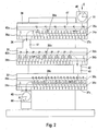
- FIG. 2 shows a cascade with three troughs 30, 31, 32 arranged one above the other drying sludge passes through a product entry 33 into an upper trough 30 upper trough are a screw conveyor 34a for conveying the introduced sludge and a padel shaft 35a is arranged one above the other for circulating the introduced sludge.
- the transport screw 34a With the help of the transport screw 34a, the introduced sludge becomes a trough discharge 36 of the upper trough 30 transported.
- the sludge is removed using the transport screw 34a and the paddle shaft 35a continuously circulated and mixed. Through contact the sludge is dried with the heated trough walls.
- the screw blades 37a of the transport screws 34a and the paddles grip 38a of the paddle shafts 35a at least partially one inside the other.
- the Transport screws 34a and the paddle shaft 35a comb through the screw vanes 37a and the paddles 38a.
- the layer thickness of the sludge in a space between the screw blades 37a and the paddles 38a compared to a trough with only one single conveyor screw essentially halved. This halving of the layer thickness leads to more effective heat transfer from the heated parts of the troughs to the drying mud.
- the sludge After passing through the trough discharge 36, the sludge reaches an upper intermediate section 41 and falls through it into a middle trough 31.
- the sludge In the middle Trough 31, the sludge is conveyed in one direction by means of the screw conveyor 34b, which is opposite to a conveying direction in the upper trough 30.
- a paddle wave 35b is used to circulate the sludge.
- Through a trough discharge 42 of the middle trough 30 and the sludge then passes through a lower connecting portion 43 into a lower one Trough 32.
- the sludge is again transported using the screw conveyor 34c promoted and in this way reaches a product discharge 44.
- a paddle shaft 35c supports the circulation of the sludge to be dried.
- the distance between adjacent paddles is paddle 38b on the paddle shaft 35b less than the distance between adjacent paddles of the paddles 38a on the paddle shaft 35a, so that the number of paddles 38b greater than the number of Paddle 38a is.
- the same statement applies in relation to the paddles 38c on the paddle shaft 35c and the paddle 38b on the paddle shaft 35b.
- Increasing the number of paddles in successive troughs has the advantage that particles of the dry matter contained in one of the Troughs were created under the influence of the paddle wave in the trough that followed Using a paddle shaft can be further crushed to the same length as the paddle shaft but has a higher number of paddles in the previous trough. To this The dry material is shredded piece by piece.
- the number and the Positioning of the paddles 38a, 38b and 38c on the incline of the transport screws 35a, 35b or 35c adapted so that combing the paddles 38a, 38b or 38c and the screw wing 37a, 37b and 37c is guaranteed.
- the product entry 33 and the product discharge 44 are made using an entry lock 45 or a discharge lock 46 opened and closed.
- a delivery space 47 can be closed airtight, which is between the product entry 33 and the product discharge 44 through the troughs 30, 31, 32 and the upper one and the lower connecting portion 41, 33 extends therethrough. This prevents that false air, in particular ambient air, enters the delivery chamber 47.
- In the funding room 47 is done by heating the troughs and optionally heating the conveyor screws 34a-34c and / or the paddle shafts 35a-35c a very high temperature, preferably about 300 ° C, generated to dry the sludge.
- the intrusion of bad air For example, from ambient air, has a cooling effect and is effective when drying the Sludge counterproductive.
- the airtight sealing of the delivery space 47 with the help of the entry lock 45 and the Discharge lock 46 also serves to improve safety when operating the device for drying mud.
- the sewage sludge drying produces fine dust. This fine dust is stored in troughs 30, 31, 32 and in the suction system 17 (see FIG. 1). The fine dust begins at around 120 ° C with the development of heat to oxidize. This can lead to dreaded and dangerous fine dust deflagrations and lead to plant fires. This is done with the help of the entry lock 47 and the discharge lock 46 thereby prevents no air in the troughs 30, 31, 32 and the suction system 17 arrives, so that only vapors, i.e. saturated steam is present. Thus the Safety of sewage sludge drying units significantly improved.
- the entry lock 45 can expediently be designed as a metering lock to the To be able to control the amount of sludge to be introduced.
- the suction system 17 can be compared to the Outside air and / or the delivery space 47 by suitable measures, e.g. Valves, locks or the like. Be insulated so that no false air can enter through the suction system.
- suitable measures e.g. Valves, locks or the like.
- the entry lock 45 and the discharge lock 46 for airtight Closing the delivery space 47 is also provided in a drying device can be, in which only a single screw is arranged in the troughs, as it is known from the prior art.
- the beneficial effect of airtight sealing of the delivery space 47 with the aid of the entry lock 45 and the discharge lock 46 also given in this case without restriction.
- a conveying space between product entry and product discharge with the help of an entry lock and a Discharge lock can be closed airtight.
- the product entry closed with the entry lock and the product discharge with the discharge lock his.
- FIG. 3 shows a side view with two cascades 60, 61, each with three troughs 62a, 63a, 64a and 62b, 63b, 64b.
- the cascades 60, 61 can, for example, the trough arrangement with the troughs 30, 31, 32 according to Figure 2 correspond.
- the one to be dried Sludge enters the respective cascade 60, 61 through a product entry 65a or 65b and is in the troughs 62a, 63a, 64a and 62b, 63b, 64b each with the help of a screw conveyor 66a, 66b and 66c and a further screw conveyor 67a, 67b and 67c.
- the sludge to be dried finally arrives in the respective cascade 60, 61 a product discharge 68a or 68b.
- a paddle shaft 70 or 71 for circulating and Crushing the sludge is arranged so that a central longitudinal axis of the Paddle shafts 70, 71 each parallel to a central longitudinal axis of the screw conveyor 66a or the further screw conveyor 67a.
- the paddle shafts 70, 71 are also arranged in a horizontal plane which lies above the horizontal plane in which the screw conveyor 66a and the further screw conveyor 67a are arranged.
- paddle 72, 73 of the paddle shafts 70, 71 mesh with one another with the screw blades 68 and 69, respectively when circulating and conveying the dry material.
- FIG. 3 With the aid of arrows A1 it is shown in FIG. 3 how the vapors are using a suction device 80 are sucked off via the evaporation surfaces 74.
- the Vapors of the two cascades 60, 61 passed in a common exhaust duct 75, which between the cascades is arranged.
- the exhaust duct 75 is with the help formed by channel components 77.
- the channel components 77 are mechanical Properties, in particular with regard to a material used and a material thickness and a profile design, designed so that a support structure by means of the channel components 77 is formed, on which the troughs 62a, 63a, 64a and 62b, 63b, 64b are arranged.
- the channel components 77 thus perform two very different functions: forming the exhaust air duct 75 for removing the vapors and forming a supporting structure for the troughs 62a, 63a, 64a and 62b, 63b, 64b. This saves material. Regardless of the specific training the troughs 62a, 63a, 64a or 62b, 63b, 64b and the circulation / drying components arranged therein, in particular the arrangement and design of the paddle shafts 70, 71, is a drying system with the help of the described construction of the channel components 77 created that, compared to known systems, those formed by means of the channel components 77, has multifunctional exhaust air duct 75.
- the two cascades 60, 61 can be operated independently of one another.
- the individual troughs each have an individual drive, which operates independently of at least the drive of the troughs of the other cascade can, as well as that the troughs of each cascade have a common drive, which can be operated independently of the drive of the other cascade.
- the drive of the screw conveyors of cascades connected in series in a cascade can be coupled so that the conveying direction in the corresponding troughs simultaneously is reversed. It can also be provided that the troughs 30, 31, 32 (see FIG. 2) or 62a, 63a, 64 and / or 62b, 63b, 64 (see FIG. 3) each have their own separate drives.
- the conveying direction of all transport screws can be selected reversed in a cascade or just the conveying direction of screw conveyors in part of the troughs, for example only in one trough, during the conveying direction remains unchanged for the other troughs.
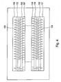
- Figure 4 shows a schematic representation of two troughs arranged side by side 100, 101 with two transport screws 102, 103 and 104, 105 from above.
- two transport screws 102, 103 and 104, 105 can be, for example, the troughs 62a and 62b and the transport screw 66a and the further transport screw 67a act.
- Wings 106, 107 and 108, 109 of the two Transport screws 102, 103 and 104, 105 mesh with each other when turning, so that the Layer thickness of the dry material is reduced.
Landscapes
- Engineering & Computer Science (AREA)
- Mechanical Engineering (AREA)
- Life Sciences & Earth Sciences (AREA)
- Hydrology & Water Resources (AREA)
- Environmental & Geological Engineering (AREA)
- Water Supply & Treatment (AREA)
- Chemical & Material Sciences (AREA)
- Organic Chemistry (AREA)
- General Engineering & Computer Science (AREA)
- Drying Of Solid Materials (AREA)
- Treatment Of Sludge (AREA)
Abstract
Die Erfindung betrifft eine Vorrichtung zum Trocknen von Schlamm, insbesondere Klär- oder Faulschlamm, mit einer Transporteinrichtung zum Fördern des Schlamms zwischen einem Produkteintrag (65a) und einem Produktaustrag (68a) und einer Heizeinrichtung zum Aufheizen des Schlamms in der Transporteinrichtung, wobei die Transporteinrichtung mindestens einen Trog (62a) umfaßt und wobei in einem Innenraum des wenigstens einen Trogs (62a) eine Transportschnecke (66a) mit Flügeln (68) zum Fördern des Schlamms angeordnet ist. Im Innenraum des wenigstens einen Trogs (62a) ist wenigstens eine Paddelwelle (70) mit Paddeln (72) zum Umwälzen des Schlamms vorgesehen. <IMAGE>The invention relates to a device for drying sludge, in particular sewage or digested sludge, with a transport device for conveying the sludge between a product inlet (65a) and a product discharge (68a) and a heating device for heating up the sludge in the transport device, the transport device at least comprises a trough (62a) and a transport screw (66a) with wings (68) for conveying the sludge is arranged in an interior of the at least one trough (62a). At least one paddle shaft (70) with paddles (72) for circulating the sludge is provided in the interior of the at least one trough (62a). <IMAGE>
Description
Die Erfindung betrifft eine Vorrichtung zum Trocknen von Schlamm, insbesondere von Kläroder Faulschlamm, mit einer Transporteinrichtung zum Fördern des Schlamms zwischen einem Produkteintrag und einem Produktaustrag, und einer Heizeinrichtung zum Aufheizen des Schlamms in der Transporteinrichtung, wobei die Transporteinrichtung wenigstens einen Trog umfaßt, und wobei in einem Innenraum des wenigstens einen Trogs eine Transportschnecke mit Flügeln zum Umwälzen und Fördern des Schlamms angeordnet ist.The invention relates to a device for drying sludge, in particular sewage or Digested sludge, with a transport device for conveying the sludge between one Product entry and a product discharge, and a heating device for heating the Sludge in the transport device, wherein the transport device at least one Includes trough, and wherein in an interior of the at least one trough a conveyor screw is arranged with wings for circulating and conveying the sludge.
Derartige Vorrichtungen werden benutzt, um den in Kläranlagen anfallenden Klär- bzw. Faulschlamm mit hoher Schadstoffbeladung und großem Wassergehalt für eine Deponierung vorzubereiten. Auch kontaminiertes Erdreich, wie es beispielsweise nach einem Chemieunfall, einem Müllunfall oder dergleichen abgetragen wird, kann in einer solchen Vorrichtung behandelt werden.Devices of this type are used to treat the sewage or digested sludge occurring in sewage treatment plants prepare for landfilling with a high pollutant load and high water content. Contaminated soil, such as after a chemical accident, a garbage accident or the like can be treated in such a device become.
Aus der Druckschrift G 88 16 171 ist eine Vorrichtung der eingangs beschriebenen Art bekannt. Der zu trocknende Schlamm, welcher zuvor beispielsweise im Rahmen einer Entwässerung behandelt sein kann, wird über den Produkteintrag in einem Trog eingebracht. In dem Trog ist eine Schneckenwelle angeordnet, die mit Hilfe einer Drehbewegung den eingebrachten Schlamm fördert. Gemäß der bekannten Vorrichtung sind mehrere Tröge in einer Kaskade übereinander angeordnet. Der zu trocknende Schlamm gelangt entlang der Kaskade von dem Produkteintrag zu einem Produktaustrag. Hierbei wird der Schlamm in den Trögen jeweils von einem Trogeintrag zu einem Trogaustrag gefördert. Von dem Trogaustrag eines übergeordneten Trogs gelangt der Schlamm in den Trogeintrag eines darunterliegenden Trogs. Zwischen dem Trogaustrag des übergeordneten Trogs und dem Trogeintrag des darunterliegenden Trogs ist zur Führung des Schlamms ein Zwischenabschnitt ausgebildet.From the document G 88 16 171 a device of the type described above is known. The sludge to be dried, which was previously used, for example, as part of a drainage can be treated, is introduced via the product entry in a trough. By doing A worm shaft is arranged in the trough Promotes mud. According to the known device, several troughs are in a cascade arranged one above the other. The sludge to be dried passes along the cascade from the Product entry for a product discharge. Here, the mud in each of the troughs promoted from a trough entry to a trough discharge. From the trough discharge of a parent The sludge enters the trough in a trough below. Between the trough discharge of the superordinate trough and the trough discharge of the one below An intermediate section is formed for troughs for guiding the sludge.
Um den Schlamm zu trocknen, werden sowohl die Tröge als auch die Transportschnecken beheizt, so daß der Schlamm erhitzt wird und Wasserbestandteile verdampfen. Zu diesem Zweck sind Trogwände doppelwandig ausgebildet, so daß die Trogwände von einem erhitzen Medium, insbesondere Öl durchströmt werden können. Des weiteren ist vorgesehen, daß eine Welle der Transportschnecken ebenfalls doppelwandig ausgebildet ist, so daß die Welle von dem erhitzten Medium durchströmt werden kann.To dry the sludge, both the troughs and the screw conveyors heated so that the sludge is heated and water components evaporate. To this Purpose are double-walled trough walls so that the trough walls heat from one Medium, especially oil can be flowed through. Furthermore, it is provided that a Shaft of the screw conveyor is also double-walled, so that the shaft of can flow through the heated medium.
Beim Erhitzen des Schlamms entstehen Brüden, die mit Hilfe einer Absaugeinrichtung abgesaugt werden. Zu diesem Zweck ist jeder der Tröge mit der Absaugeinrichtung verbunden.When the sludge is heated, vapors are formed which are sucked off with the aid of a suction device become. For this purpose, each of the troughs is connected to the suction device.
Aufgabe der vorliegenden Form ist es, eine verbesserte Vorrichtung der eingangs beschriebenen Art mit einer erhöhten Effizienz hinsichtlich der Schlammtrocknung zu schaffen.The object of the present form is to provide an improved device as described in the introduction To create species with an increased efficiency in terms of sludge drying.
Diese Aufgabe wird bei einer Vorrichtung gemäß dem Oberbegriff des Anspruchs 1 erfindungsgemäß dadurch gelöst, daß im Innenraum des wenigstens einen Trogs wenigstens eine Paddelwelle mit Paddeln zum Umwälzen des Schlamms vorgesehen ist. This object is achieved in a device according to the preamble of claim 1 solved in that at least one in the interior of the at least one trough Paddle shaft with paddles for circulating the sludge is provided.
Bei der Trocknung des Schlamms ist es von wesentlicher Bedeutung, daß der zu trocknende Schlamm so weit wie möglich verkleinert wird, da der Schlamm hierdurch leichter mit Hilfe der Heizeinrichtung aufgeheizt und somit getrocknet werden kann. Ein wichtiger Vorteil, welcher mit der Erfindung gegenüber dem Stand der Technik erreicht ist, besteht darin, daß mit Hilfe der Paddel der wenigstens einen Paddelwelle eine zusätzliche Zerkleinerung des Trockenguts erreicht wird. Der Wärmeübergang auf das Trockengut ist um so besser je kleiner die Brocken des Trockenguts sind.When drying the sludge, it is essential that the one to be dried Mud is reduced as much as possible, as this makes the mud easier to use the heating device can be heated and thus dried. An important advantage which is achieved with the invention compared to the prior art is that with the help of the paddles of the at least one paddle shaft, an additional comminution of the Dry goods is reached. The smaller the heat transfer to the dry goods, the better are the chunks of dry goods.
Neben der verbesserten Zerkleinerung ergibt sich bei der Erfindung weiterhin der Vorteil, daß eine wesentlich bessere Durchmischung des zu trocknenden Schlamms stattfindet. Auf diese Weise werden immer neue Trockengutteile mit der Heizeinrichtung in Kontakt gebracht und hierdurch getrocknet. Die kontinuierliche Durchmischung des Schlamms führt dazu, daß Teilchen des Schlamms, die zunächst von anderen Teilchen des Schlamms so umgeben sind, daß sie nicht mit den beheizten Flächen, z.B. beheizten Trögen oder Schneckenflügeln, in Kontakt treten, freigelegt werden, so daß auch diese Teilchen getrocknet werden können. Das kontinuierliche Umwälzen mit Hilfe der Paddelwelle verhindert die Bildung größerer Klumpungen in den Trögen, welche die Effektivität des Trocknungsprozesses vermindern.In addition to the improved size reduction, the invention also has the advantage that a much better mixing of the sludge to be dried takes place. To this In this way, new dry goods parts are brought into contact with the heating device and thereby dried. The continuous mixing of the sludge leads to particles of the sludge, which are initially surrounded by other particles of the sludge so that not with the heated surfaces, e.g. heated troughs or snail wings, in contact occur, are exposed so that these particles can be dried. The continuous circulation using the paddle shaft prevents the formation of larger clumps in the troughs, which reduce the effectiveness of the drying process.
Eine zweckmäßige Weiterbildung der Erfindung sieht vor, daß die Paddelwelle oberhalb der Transportschnecke angeordnet ist. Hierdurch wird der Querschnitt der Tröge quer zur Längsrichtung der Transportschnecke möglichst gering gehalten. Dieses hat den Vorteil, daß eine möglichst kleine Ausdampffläche erreicht ist, was im Zusammenhang mit der Gestaltung von Absaugeinrichtungen zum Absaugen der bei der Trocknung des Schlamms entstehenden Brüden zweckmäßig ist.An expedient development of the invention provides that the paddle shaft above the Transport screw is arranged. As a result, the cross section of the troughs is transverse to the longitudinal direction the transport screw is kept as low as possible. This has the advantage that a The smallest possible evaporation area is reached, which is in connection with the design of Suction devices for sucking off the vapors formed during the drying of the sludge is appropriate.
Zur Verbesserung der Umwälzung des Trockenguts sieht eine vorteilhafte Ausgestaltung der Erfindung vor, daß beim Umwälzen des Schlamms die Paddel der Paddelwelle mit den Flügeln der Transportschnecke ineinander greifen.In order to improve the circulation of the dry material, an advantageous embodiment of the Invention before that when circulating the mud, the paddles of the paddle shaft with the wings of the screw conveyor interlock.
Um das Trockengut möglichst effektiv umzuwälzen und innerhalb des Trogs zu fördern, kann bei einer Fortbildung der Erfindung vorgesehen sein, daß neben der Transportschnecke wenigstens eine weitere Transportschnecke vorgesehen ist, daß die Transportschecke und die wenigstens eine weitere Transportschnecke in einer horizontalen Ebene nebeneinander angeordnet sind und daß oberhalb der wenigstens eine weitere Transportschnecke zumindest eine weitere Paddelwelle mit Paddeln zum Umwälzen des Schlamms angeordnet ist.In order to circulate the dry material as effectively as possible and convey it within the trough in a further development of the invention it should be provided that in addition to the screw conveyor at least a further screw conveyor is provided that the transport screw and the at least one further screw conveyor arranged side by side in a horizontal plane are and that above the at least one further screw conveyor at least one Another paddle shaft with paddles for circulating the sludge is arranged.
Zur Verbesserung der Wirkung der Paddelwellen sieht eine zweckmäßige Ausführungsform der Erfindung vor, daß beim Umwälzen des Schlamms die Paddel der einen Paddelwelle und die Paddel der zumindest einen weiteren Paddelwelle ineinander greifen.To improve the effect of the paddle waves provides an expedient embodiment the invention that when the sludge is circulated, the paddles of a paddle shaft and the paddles of the at least one further paddle shaft interlock.
Das vorteilhafte Zusammenwirken von Transportschnecke und Paddelwelle ist bei einer Ausführungsform der Erfindung dadurch besonders zweckrnäßig gestaltet, daß die Paddelwelle oberhalb der Transportschnecke und die zumindest eine weitere Paddelwelle oberhalb der wenigstens einen weiteren Transportschnecke so angeordnet sind, daß eine Mittelachse der Paddelwelle in Längsrichtung und eine Mittelachse der Transportschnecke in Längsrichtung sowie eine Mittelachse der zumindest einen weiteren Paddelwelle in Längsrichtung und eine Mittelachse der wenigstens einen weiteren Transportschnecke in Längsrichtung jeweils im wesentlichen in einer vertikalen Ebene liegen.The advantageous interaction of the screw and the paddle shaft is in one embodiment the invention particularly expediently designed that the paddle shaft above the screw conveyor and the at least one further paddle shaft above the at least one further screw conveyor are arranged so that a central axis of the Paddle shaft in the longitudinal direction and a central axis of the screw conveyor in the longitudinal direction and a central axis of the at least one further paddle shaft in the longitudinal direction and a Central axis of the at least one further screw conveyor in the longitudinal direction in each case lie essentially in a vertical plane.
Zur Verbesserung der Durchmischung des Trockenguts kann ergänzend vorgesehen sein, daß die Paddel der zumindest einen weiteren Paddelwelle und die Flügel der wenigstens einen weiteren Transportschnecke beim Umwälzen des Schlamms jeweils ineinander kämmen. Hierdurch wird die Dicke von Klumpen des Trockenguts wesentlich vermindert, beispielsweise um die Hälfte.To improve the mixing of the dry material it can additionally be provided that the paddles of the at least one further paddle shaft and the wings of the at least one comb each other auger while circulating the sludge. This significantly reduces the thickness of lumps of the dry material, for example by half.
Bei einer zweckmäßigen Fortbildung der Erfindung kann vorgesehen sein, daß die Transportschnecke und/oder die wenigstens eine weitere Transportschnecke jeweils als eine Schnekkenwelle ausgebildet sind, wodurch eine mechanisch stabile und der hohen Beanspruchung bei der Förderung des Schlamms in den Trögen genügende Transportschnecke geschaffen ist.In an expedient development of the invention it can be provided that the transport screw and / or the at least one further screw conveyor each as a worm shaft are trained, creating a mechanically stable and high stress sufficient conveying screw is created in the conveyance of the sludge in the troughs.
Bei einer Ausgestaltung der Erfindung ist vorgesehen, daß die Transportschnecke und die wenigstens eine weitere Transportschnecke mechanisch miteinander gekoppelt sind, wodurch die Drehbewegung der Transportschnecke und der wenigstens einen weiteren Transportschnecke aufeinander so abgestimmt werden können, daß der Schlamm optimal gefördert und somit getrocknet wird. Darüber hinaus ist es auf diese Weise möglich, die Transportschnecke und die wenigstens einer weiteren Transportschnecke mit Hilfe eines einzelnen Getriebes anzutreiben.In one embodiment of the invention it is provided that the screw conveyor and the at least one further screw conveyor are mechanically coupled to each other, whereby the rotational movement of the screw conveyor and the at least one further screw conveyor can be coordinated so that the sludge is optimally conveyed and is thus dried. In addition, it is possible in this way, the transport screw and to drive the at least one further screw conveyor by means of a single gear.
Eine vorteilhafte Weiterbildung der Erfindung sieht vor, daß die Transportschnecke und die wenigstens eine weitere Transportschnecke so miteinander gekoppelt sind, daß die Transportschnecke und die wenigstens eine weitere Transportschnecke mit einer gemeinsamen Drehgeschwindigkeit drehbar sind. Hierdurch ist eine kontinuierliche und gleichmäßige Förderung des Schlamms in den Trögen ermöglicht.An advantageous development of the invention provides that the screw conveyor and the at least one further screw conveyor are coupled together so that the screw conveyor and the at least one further screw conveyor with a common rotational speed are rotatable. This is a continuous and even promotion of the mud in the troughs.
Eine zweckmäßige Ausgestaltung der Erfindung kann vorsehen, daß die Transportschnecke und die wenigstens eine weitere Transportschnecke so miteinander gekoppelt sind, daß eine Drehrichtung der Transportschnecke entgegengesetzt zu einer Drehrichtung der wenigstens einer weiteren Transportschnecke ausgebildet ist, wodurch die Umwälzung des Schlamms in den Trögen optimiert wird.An expedient embodiment of the invention can provide that the screw conveyor and the at least one further screw conveyor are coupled to one another such that a Direction of rotation of the screw conveyor opposite to a direction of rotation of at least a further screw conveyor is formed, whereby the circulation of the sludge in the trough is optimized.
Eine zweckmäßige Fortbildung der Erfindung sieht vor, daß die Transportschnecke und die wenigstens eine weiter Transportschnecke mittels einer Zahnradverbindung miteinander gekoppelt sind. Hierdurch ist zwischen den Transportschnecken eine mechanisch stabile und verschleißfeste Kopplung geschaffen.A useful development of the invention provides that the screw and the at least one further screw conveyor coupled together by means of a gear connection are. As a result, a mechanically stable and wear-resistant coupling created.
Bei einer vorteilhaften Ausgestaltung der Erfindung ist die Zahnradverbindung mit Hilfe eines Zahnradpaares ausgebildet, wobei das Zahnradpaar ein Übersetzungsverhältnis von 1:1 aufweist. Hierdurch ist zwischen den Transportschnecken eine mechanisch einfache Kopplung geschaffen, die gewährleistet, daß die Transportschnecken mit derselben Drehzahl pro Zeiteinheit bewegt werden.In an advantageous embodiment of the invention, the gear connection is by means of a Gear pair formed, the gear pair has a gear ratio of 1: 1. As a result, there is a mechanically simple coupling between the transport screws created, which ensures that the screw conveyors at the same speed per Unit of time can be moved.
Um einen Modulaufbau der Vorrichtung zum Trocknen von Schlamm zu unterstützen, kann bei einer Weiterbildung der Erfindung vorgesehen sein, daß die Transportschnecke mit einem Aufsteckgetriebe zum Antreiben einer Drehbewegung der Transportschnecke kraftschlüssig verbunden ist.In order to support a modular construction of the device for drying sludge, in a further development of the invention, it is provided that the transport screw with a Slip-on gear for driving a rotary movement of the screw conveyor in a force-locking manner connected is.
Eine zweckmäßige Ausführungsform der Erfindung sieht vor, daß die Drehrichtung der Transportschnecke und die Drehrichtung der wenigstens einen weiteren Transportschnecke mindestens kurzzeitig jeweils umkehrbar sind, so daß die Förderung des Schlamms wenigstens teilweise umgekehrt wird. Mit Hilfe der Umkehrbarkeit der jeweiligen Drehrichtung kann eine längere Verweildauer des Schlamms in einem Trog erreicht werden, so daß die Schlammpartikel für eine längere Zeit erhitzt werden, um den Trocknungsprozeß des Schlamms zu optimieren. Darüber hinaus, bewirkt eine kurzzeitige Umkehr der Drehrichtung eine intensivere Durchmischung des Schlamms.An advantageous embodiment of the invention provides that the direction of rotation Transport screw and the direction of rotation of the at least one further transport screw are reversible at least for a short time, so that the conveyance of the sludge at least is partially reversed. With the help of the reversibility of the respective direction of rotation a longer residence time of the sludge can be achieved in a trough, so that the Mud particles are heated for a long time to complete the drying process of the Optimize sludge. In addition, the direction of rotation is briefly reversed more intensive mixing of the sludge.
Bei einer bevorzugten Ausgestaltung der Erfindung sind die Flügel der Transportschnecke und/oder die Flügel der wenigstens einen weiteren Transportschnecke beheizt, wodurch die beheizte Fläche vergrößert ist, die zum Erhitzen und somit zur Trocknung des Schlamms in dem Trog genutzt wird.In a preferred embodiment of the invention, the wings of the screw conveyor are and / or the wings of the at least one further screw conveyor are heated, whereby the heated area is increased, which for heating and thus drying the sludge in the trough is used.
Bei einer Fortbildung der Erfindung sind die Flügel der Transportschnecke bzw. die Flügel der wenigstens einen weiteren Transportschnecke wenigstens in Teilbereichen jeweils doppelwandig ausgebildet, so daß die Flügel der Transportschnecke bzw. die Flügel der wenigstens einen weiteren Transportschnecke zum Beheizen von einem Medium durchströmt werden können. Hierdurch kann in den Flügeln jeweils ein erhitztes Medium eingebracht werden, beispielsweise Öl, um den Trockungsprozeß des Schlamms zu unterstützen.In a development of the invention, the wings of the screw conveyor or the wings the at least one further screw conveyor at least in some areas has double walls trained so that the wing of the screw conveyor or the wing of at least another transport screw for heating can be flowed through by a medium can. As a result, a heated medium can be introduced into the wings, for example oil to aid the drying process of the sludge.
Die Erfindung sieht insbesondere auch eine Vorrichtung zum Trocknen von Schlamm, insbesondere Klär- oder Faulschlamm, mit einer Transporteinrichtung zum Fördern des Schlamms zwischen einem Produkteintrag und einem Produktaustrag, und einer Heizeinrichtung zum Aufheizen des Schlamms in der Transporteinrichtung vor, wobei die Transporteinrichtung wenigstens einen Trog umfaßt und wobei in einem Innenraum des wenigstens einen Trogs eine Transportschnecke mit Schneckenflügeln zum Umwälzen und Fördern des Schlamms angeordnet ist, welche durch eine Einrichtung zum Verhindern oder Behindern des Eindringens von kälterer Luft in einen beheizten Bereich der Transporteinrichtung gekennzeichnet ist. Die Erfindung kann insbesondere eine solche Vorrichtung vorsehen, welche dadurch gekennzeichnet ist, daß eine Eintragsschleuse, vorzugsweise im Bereich des Produkteintrags, und eine Austragsschleuse, vorzugsweise im Bereich des Produktaustrags, zum luftdichten Abschließen eines Förderraums angeordnet sind, der sich in der Transporteinrichtung zwischen dem Produkteintrag und dem Produktaustrag erstreckt. Das luftdichte Abschließen des Förderraums mit Hilfe der Eintrags- und der Austragsschleuse verhindert beim Absaugen der Brüden aus den Trögen, daß Falschluft angesaugt wird. Falschluft umfaßt in diesem Zusammenhang jegliche Luft, insbesondere Umgebungsluft der Vorrichtung zum Trocknen, deren Temperatur sich wesentlich von der Betriebstemperatur in den Trögen unterscheidet. In den Trögen herrscht beispielsweise eine Betriebstemperatur von ca. 300° C. Die Umgebungstemperatur der Vorrichtung kann je nach Jahreszeit zwischen +30° C und etwa -10° C liegen. Der Eintritt von Falschluft in die Tröge hat somit eine enorme Kühlwirkung und ist kontraproduktiv. Mit Hilfe der Eintrags- und Austragsschleuse wird einerseits der Eintritt derartiger kühlender Falschluft verhindert. Andererseits verhindern die Eintrags- und die Austragsschleuse den Austritt warmer Luft aus den Trögen. Hierdurch wird insgesamt der Wirkungsgrad der Vorrichtung zum Trocknen des Schlamms verbessert. Darüber hinaus genügt aufgrund des luftdichten Abschluß des Förderraums ein geringer Unterdruck, um die Brüden abzusaugen. Diese Vorrichtung kann insbesondere mehrere Transportschnecken, wie vorangehend beschrieben, aufweisen.In particular, the invention also provides a device for drying sludge, in particular Sewage or digested sludge, with a transport device for conveying the sludge between a product entry and a product discharge, and a heating device for Preheating the sludge in the transport device, the transport device comprises at least one trough and being in an interior of the at least one trough a screw conveyor with screw blades for circulating and conveying the sludge is arranged by a device for preventing or hindering the intrusion characterized by colder air in a heated area of the transport device is. The invention can in particular provide such a device, which is characterized in that is that an entry lock, preferably in the area of the product entry, and a discharge lock, preferably in the area of the product discharge, for airtight Completing a conveying space are arranged, which is located in the transport device between the product entry and the product discharge. The airtight sealing of the Conveying space with the help of the entry and the discharge lock prevents when the Brothers from the troughs that false air is sucked in. In this context, false air includes any air, in particular ambient air of the device for drying, the Temperature differs significantly from the operating temperature in the troughs. In the Troughs, for example, have an operating temperature of approx. 300 ° C. The ambient temperature the device can be between + 30 ° C and about -10 ° C depending on the season. The The entry of false air into the troughs has an enormous cooling effect and is counterproductive. With the help of the entry and discharge lock, on the one hand the entry of such cooling false air prevented. On the other hand, the entry and discharge locks prevent warm air escaping from the troughs. This makes the overall efficiency improved the device for drying the sludge. In addition, due to the airtight closure of the delivery chamber a little negative pressure to the vapors suck. In particular, this device can have a plurality of screw conveyors, as above described.
Um mit Hilfe eines geringen mechanischen Aufwands eine gemeinsame Drehung der Paddelwelle und der Transportschnecke zu erreichen, sieht eine zweckmäßige Fortbildung der Erfindung vor, daß die Paddel selbst mechanisch an die Transportschnecke gekoppelt ist.In order to enable a common rotation of the paddle shaft with the help of little mechanical effort and to reach the screw conveyor sees an appropriate training of Invention before that the paddle itself is mechanically coupled to the screw conveyor.
Eine Übertragung einer Drehbewegung der Paddelwelle auf die zumindest eine weitere Paddelwelle ist bei einer zweckmäßigen Ausgestaltung der Erfindung dadurch erreicht, daß die zumindest eine weitere Paddelwelle an die Paddelwelle mechanisch gekoppelt ist, so daß die zumindest eine weitere Paddelwelle und die Paddelwelle gemeinsam drehbar sind. A transmission of a rotary movement of the paddle shaft to the at least one further paddle shaft is achieved in an expedient embodiment of the invention in that the at least one further paddle shaft is mechanically coupled to the paddle shaft, so that the at least one further paddle shaft and the paddle shaft can be rotated together.
Die Erfindung stellt weiterhin eine Vorrichtung zum Trocknen von Schlamm, insbesondere Klär- oder Faulschlamm, mit einer Transporteinrichtung zum Fördern des Schlamms zwischen einem Produkteintrag und einem Produktaustrag und einer Heizeinrichtung zum Aufheizen des Schlamms in der Transporteinrichtung, wobei die Transporteinrichtung wenigstens einen Trog umfaßt und wobei in einem Innenraum des wenigstens einen Trogs eine Transportschnecke mit Schneckenflügeln zum Umwälzen und Fördern des Schlamms angeordnet ist, zur Verfügung, welche dadurch gekennzeichnet ist, daß, einem oder mehreren Trögen vorgeschaltet, insbesondere in einem Verbindungsabschnitt der Transporteinrichtung zwischen benachbarten Trögen, eine Zerkleinerungseinrichtung angeordnet ist. Dadurch kann der Schlamm vor dem Eintritt in einen Trog oder beim Übergang zwischen benachbarten Trögen zusätzlich zerkleinert werden, um wiederum insgesamt die Größe der Schlammpartikel zu vermindern, die von dem Produkteintrag zum Produktaustrag befördert werden. Kleinere Schlammpartikel haben den Vorteil, daß sie effizienter getrocknet werden können. Auch diese Ausführungsform der Erfindung kann mit mehreren Transportschnecken und/oder einem isolierten Bereich der Transporteinrichtung, z.B. mit einer Eintragsschleuse und einer Austragsschleuse, versehen sein, wie dies vorangehend beschrieben wurde.The invention further provides a device for drying sludge, in particular Sewage or digested sludge, with a transport device for conveying the sludge between a product entry and a product discharge and a heating device for heating of the sludge in the transport device, the transport device at least comprises a trough and a transport screw in an interior of the at least one trough arranged with screw blades for circulating and conveying the sludge is available, which is characterized in that one or more troughs upstream, in particular in a connecting section of the transport device between adjacent troughs, a shredding device is arranged. This allows the Mud before entering a trough or at the transition between neighboring troughs are additionally crushed in order to increase the overall size of the sludge particles reduce that are transported from the product entry to the product discharge. smaller Sludge particles have the advantage that they can be dried more efficiently. This too Embodiment of the invention can be with multiple screw conveyors and / or an isolated Area of the transport device, e.g. with an entry lock and a discharge lock, be provided as described above.
Vorteilhaft weist die Zerkleinerungseinrichtung wenigstens zwei Messerwalzen auf, die zueinander gegenläufig drehbar sind. Hierdurch wird die Zerkleinerungseinrichtung mit Hilfe mechanisch einfacher und leistungsfähiger Mittel gebildet.The comminution device advantageously has at least two knife rollers which are in relation to one another are rotated in opposite directions. This will help the shredding device mechanically simple and powerful means.
Zweckmäßig kann vorgesehen sein, daß die wenigstens zwei Messerwalzen in einer Ebene benachbart zueinander angeordnet sind, die sich im wesentlichen in einer Längsrichtung der benachbarten Tröge erstreckt. Hierdurch werden von der Zerkleinerungseinrichtung alle Schlammpartikel erfaßt, die von einem der benachbarten Tröge in den darunterliegenden Trog fallen.It can expediently be provided that the at least two knife rollers in one plane are arranged adjacent to each other, which are substantially in a longitudinal direction of the neighboring troughs extends. As a result, all of the shredding device Mud particles captured by one of the neighboring troughs in the trough below fall.
Es kann weiterhin vorgesehen sein, daß die Vorrichtung mehrere Tröge aufweist, die in einer oder mehreren Kaskaden angeordnet sind, und/oder die Tröge und/oder die eine oder mehreren Kaskaden parallel betrieben werden können. Die parallel betriebenen Tröge oder Kaskaden bilden somit mehrere Trocknungspfade und können insbesondere unabhängig voneinander betrieben werden.. Dies hat den Vorteil, daß, wenn eine technische Störung innerhalb eines Trocknungspfades auftritt, dieser separat abgeschaltet und der Betrieb der Trocknungsvorrichtung mit einer verminderten Leistung fortgesetzt werden kann.It can further be provided that the device has a plurality of troughs, which in one or several cascades are arranged, and / or the troughs and / or the one or more Cascades can be operated in parallel. The troughs or cascades operated in parallel thus form several drying paths and can in particular be independent of one another operated. This has the advantage that if a technical fault occurs within a Drying path occurs, this is switched off separately and the operation of the drying device can continue with reduced performance.
Die Erfindung stellt insbesondere eine Vorrichtung zum Trocknen von Schlamm, insbesondere Klär- oder Faulschlamm, mit einer Transporteinrichtung zum Fördern des Schlamms zwischen einem Produkteintrag und einem Produktaustrag und mit einer Heizeinrichtung zum Aufheizen des Schlamms in der Transporteinrichtung zur Verfügung, wobei die Transporteinrichtung mehrere Tröge umfaßt und wobei in einem Innenraum der Tröge eine oder mehrere Transportschnecken mit Schneckenflügeln zum Umwälzen und Fördern des Schlamms angeordnet sind, welche dadurch gekennzeichnet ist, daß die Tröge in zwei oder mehreren parallelen Kaskaden angeordnet sind, in denen jeweils die Tröge hintereinander angeordnet sind, so daß jeder Trog von einem vorangehenden Trog Schlamm empfängt und/oder an einen nachfolgenden Trog Schlamm abgibt, wobei zumindest zwei Kaskaden unabhängig voneinander betreibbar sind.The invention particularly provides an apparatus for drying sludge, in particular Sewage or digested sludge, with a transport device for conveying the sludge between a product entry and a product discharge and with a heating device for Heating the sludge is available in the transport device, the transport device comprises several troughs and one or more in an interior of the troughs Transport screws with screw blades arranged to circulate and convey the sludge , which is characterized in that the troughs in two or more parallel Cascades are arranged in which the troughs are arranged one behind the other, so that each trough receives mud from and / or to a previous trough subsequent trough releases sludge, with at least two cascades independent of each other are operable.
Ferner kann vorgesehen sein, daß jeder Trog einen eigenen separaten Antrieb aufweist. Dadurch kann insbesondere der Betrieb eines Troges in einer Kaskade unabhängig von den anderen Trögen der jeweiligen Kaskade gestoppt bzw. die Drehrichtung der Transportschnecken umgekehrt werden, wodurch man abhängig von der Beschaffenheit des Schlammes geeignete Trocknungsprogramme durchführen kann.Furthermore, it can be provided that each trough has its own separate drive. Thereby can in particular operate a trough in a cascade independently of the others Troughs of the respective cascade stopped or the direction of rotation of the screw conveyors be reversed, making one suitable depending on the nature of the sludge Can carry out drying programs.
Es ist zweckmäßig, daß auch die Zufuhr des zu trocknenden Schlamms zu einer Kaskade unabhängig von einer anderen Kaskade abgestellt bzw. vermindert werden kann. Dadurch kann einerseits die Schlammzuführung gestoppt werden, um diese Kaskade zwecks Reparatur zu entleeren, und andererseits kann über die Anpassung der Schlammenge der Trocknungsverlauf an die individuellen Gegebenheiten in den verschiedenen Kaskaden angepaßt werden.It is appropriate that the supply of the sludge to be dried to a cascade is independent can be switched off or reduced by another cascade. This can on the one hand, the sludge supply can be stopped in order to repair this cascade empty, and on the other hand, the drying process can be adjusted by adjusting the amount of sludge can be adapted to the individual circumstances in the various cascades.
Die Erfindung wird im Folgenden anhand eines Ausführungsbeispiels unter Bezugnahme auf eine Zeichnung näher erläutert. Hierbei zeigen:
- Figur 1
- eine schematische Darstellung einer Trocknungsanlage für Schlamm;
Figur 2- eine schematische Darstellung einer Kaskade einer Trocknungsanlage von der Seite;
Figur 3- eine schematische Darstellung von zwei nebeneinander angeordneten Kaskaden einer Trocknungsanlage; und
- Figur 4
- eine schematische Darstellung von zwei nebeneinander angeordneten Trögen in Draufsicht.
- Figure 1
- a schematic representation of a drying plant for sludge;
- Figure 2
- a schematic representation of a cascade of a drying plant from the side;
- Figure 3
- is a schematic representation of two cascades of a drying system arranged side by side; and
- Figure 4
- a schematic representation of two troughs arranged side by side in plan view.
Figur 1 ist eine schematische Darstellung einer Vorrichtung zum Trocknen von Schlamm,
insbesondere Faul- oder Klärschlamm. Von einem Vorlagebehälter gelangt der zu trocknende
Schlamm über eine Zuführeinrichtung 1 zu einer Verteilereinrichtung 2. Mit Hilfe der Verteilereinrichtung
2 wird der Schlamm auf zwei Kaskaden 3, 4 verteilt, die jeweils vier Tröge 5
aufweisen. Die Tröge 5 bilden zusammen mit Verbindungsabschnitten 6, die jeweils zwischen
benachbarten der Tröge 5 angeordnet sind, einen Förderraum 7. Durch den Förderraum 7 hindurch
wird der über die Verteilereinrichtung 2 eingebrachte Schlamm von einem Produkteintrag
8 zu einem Produktaustrag 9 befördert. Der Schlamm wird hierbei in den Trögen 5 mit
Hilfe von Transportschnecken (nicht dargestellt) vorwärts transportiert und fällt durch den
jeweiligen Verbindungsabschnitt 10 aus einem oberen Trog 11 in einen unteren Trog 12.FIG. 1 is a schematic illustration of a device for drying sludge,
especially sludge or sewage sludge. The one to be dried arrives from a storage container
Sludge via a feed device 1 to a
Der durch den Produktaustrag 9 in eine Aufnahmeeinrichtung 13 gelangende getrocknete
Schlamm wird über ein Rohrsystem 14 zu einer Trockengutverladung abgeleitet.The dried one coming through the
Zur Trocknung des Schlamms werden die Tröge 5 beheizt. Zu diesem Zweck werden die Tröge
5 über eine Rohrleitungssystem 15 mit einem Medium versorgt, das mit Hilfe einer Heizeinrichtung
16 erhitzt wird. Das erhitzte Medium fließt dann durch Trogwände, die zu diesem
Zweck doppelwandig ausgebildet sind. Der Schlamm in den Trögen 5 wird auf diese
Weise erhitzt und getrocknet. Die bei der Trocknung des Schlamms entstehenden Brüden
werden mit Hilfe eines Absaugsystems 17 abgesaugt, welches mit einer Saugeinrichtung 19
und einem Brüdenwäscher 18 verbunden ist. Das Absaugsystem 17 ist mit jedem der Tröge 5
verbunden. Das Heizmedium ist vorzugsweise ein Thermalöl, kann aber auch ein Heizgas
sein. In der derzeit bevorzugten Ausführungsform wird das Heizmedium mit einer Temperatur
von ca. 300°C zugeleitet und mit einer Temperaturdifferenz von ca. 40°C abgeleitet. Anders
als in Fig. 1 dargestellt, können die Brüden auch in einem Abzugsschacht gesammelt
werden, der sich über die obersten Tröge der Kaskaden 3, 4 hinaus erstreckt, und von dessen
oberem Ende zu dem Brüdenwäscher 18 geleitet werden.The
In Figur 2 zeigt eine Kaskade mit drei übereinander angeordneten Trögen 30, 31, 32. Der zu
trocknende Schlamm gelangt über einen Produkteintrag 33 in einen oberen Trog 30. In dem
oberen Trog sind eine Transportschnecke 34a zum Fördern des eingebrachten Schlamms und
eine Padelwelle 35a zum Umwälzen des eingebrachten Schlamms übereinander angeordnet.
Mit Hilfe der Transportschnecke 34a wird der eingebrachte Schlamm zu einem Trogaustrag
36 des oberen Trogs 30 befördert. Hierbei wird der Schlamm mit Hilfe der Transportschnekke
34a und der Paddelwelle 35a kontinuierlich umgewälzt und durchmischt. Durch den Kontakt
mit den beheizten Trogwänden wird der Schlamm getrocknet.FIG. 2 shows a cascade with three
Es kann weiterhin vorgesehen sein, daß zum Trocknen des Schlamms Schneckenflügel 37a
der Transportschnecken 34a und/oder Paddel 38a der Paddelwellen 35a doppelwandig ausgebildet
sind und von dem erhitzten Medium durchströmt werden, um die Kontaktfläche zwischen
dem Schlamm und den erhitzten Bestandteilen der Vorrichtung zum Trocknen zu erhöhen.
Des weiteren können auch eine Welle 39a der Transportschnecke 34a und eine Welle 40a
der Paddelwelle 35a jeweils doppelwandig ausgebildet sein, um von dem erhitzten Medium
durchströmt zu werden.Provision can furthermore be made for
Gemäß Figur 2 greifen die Schneckenflügel 37a der Transportschnecken 34a und die Paddel
38a der Paddelwellen 35a wenigstens teilweise ineinander. Beim gegenläufigen Drehen der
Transportschnecken 34a und der Paddelwelle 35a durchkämmen sich die Schneckenflügel 37a
und die Paddel 38a. Hierdurch wird die Schichtdicke des Schlamms in einem Raum zwischen
den Schneckenflügeln 37a und den Paddeln 38a im Vergleich zu einem Trog mit nur einer
einzigen Transportschnecke im wesentlichen halbiert. Diese Halbierung der Schichtdicke
führt zu einer effektiveren Wärmeübertragung von den beheizten Teilen der Tröge auf den zu
trocknenden Schlamm.According to FIG. 2, the
Nach dem Durchtritt durch den Trogaustrag 36 gelangt der Schlamm in einen oberen Zwischenabschnitt
41 und fällt durch diesen hindurch in einen mittleren Trog 31. In dem mittleren
Trog 31 wird der Schlamm mit Hilfe der Transportschnecke 34b in einer Richtung gefördert,
die zu einer Förderrichtung in dem oberen Trog 30 entgegengesetzt ist. Eine Paddelwelle
35b dient zum Umwälzen des Schlamms. Durch einen Trogaustrag 42 des mittleren Trogs 30
und einen unteren Verbindungsabschnitt 43 hindurch gelangt der Schlamm dann in einen unteren
Trog 32. In dem unteren Trog wird der Schlamm wiederum mit Hilfe der Transportschnecke
34c gefördert und gelangt auf diese Weise zu einem Produktaustrag 44. Eine Paddelwelle
35c unterstützt das Umwälzen des zu trocknenden Schlamms.After passing through the
Hinsichtlich der Ausbildung und des Zusammenwirkens von Schneckenflügeln 37b, 37c der
Transportschnecken 34b bzw. 34c und von Paddeln 38b, 38c der Paddelwellen 35b, 35c gelten
die Ausführungen in Verbindung mit den Schneckenflügeln 37a und den Paddeln 38a entsprechend.With regard to the formation and interaction of
Wie sich aus Figur 2 ergibt, ist der Abstand zwischen benachbarten Paddeln der Paddel 38b
auf der Paddelwelle 35b geringer als der Abstand zwischen benachbarten Paddeln der Paddel
38a auf der Paddelwelle 35a, so daß die Anzahl der Paddel 38b größer als die Anzahl der
Paddel 38a ist. Die gleiche Aussage gilt im Verhältnis der Paddel 38c auf der Paddelwelle
35c und der Paddel 38b auf der Paddelwelle 35b. Die Erhöhung der Anzahl von Paddeln in
aufeinanderfolgenden Trögen hat den Vorteil, daß Partikel des Trockenguts, die in einem der
Tröge unter Einwirkung der Paddelwelle erzeugt wurden, in dem hierauf folgenden Trog mit
Hilfe einer Paddelwelle weiter zerkleinert werden, die bei gleicher Länge wie die Paddelwelle
in dem vorhergehenden Trog jedoch eine höhere Anzahl von Paddeln aufweist. Auf diese
Weise wird das Trockengut Stück für Stück zerkleinert. Grundsätzlich ist die Anzahl und die
Positionierung der Paddel 38a, 38b bzw. 38c an die Steigung der Transportschnecken 35a,
35b bzw. 35c angepaßt, so daß ein gegenseitiges Durchkämmen der Paddel 38a, 38b bzw. 38c
und der Schneckenflügel 37a, 37b bzw. 37c gewährleistet ist.As can be seen from FIG. 2, the distance between adjacent paddles is
Der Produkteintrag 33 und der Produktaustrag 44 werden mit Hilfe einer Eintragsschleuse 45
bzw. einer Austragsschleuse 46 geöffnet und geschlossen. Mit Hilfe der Eintragsschleuse 45
und der Austragsschleuse 46 ist ein Förderraum 47 luftdicht abschließbar, der sich zwischen
dem Produkteintrag 33 und dem Produktaustrag 44 durch die Tröge 30, 31, 32 und den oberen
und den unteren Verbindungsabschnitt 41, 33 hindurch erstreckt. Hierdurch wird verhindert,
daß Falschluft, insbesondere Umgebungsluft in den Förderraum 47 gelangt. In dem Förderraum
47 wird mit Hilfe des Beheizens der Tröge und optional des Beheizens der Transportschnecken
34a-34c und/oder der Paddelwellen 35a-35c eine sehr hohe Temperatur, vorzugsweise
etwa 300° C, zum Trocknen des Schlamms erzeugt. Das Eindringen von Falschluft,
beispielsweise von Umgebungsluft, hat eine Kühlwirkung und wirkt bei der Trocknung des
Schlamms kontraproduktiv.The
Das luftdichte Abschließen des Förderraums 47 mit Hilfe der Eintragsschleuse 45 und der
Austragsschleuse 46 dient weiterhin der Verbesserung der Sicherheit beim Betreiben der Vorrichtung
zum Trocknen von Schlamm. Bei der Klärschlammtrocknung kommt es zur Feinstaubentwicklung.
Dieser Feinstaub lagert sich in den Trögen 30, 31, 32 und in dem Absaugsystem
17 (vgl. Figur 1) ab. Der Feinstaub beginnt bereits bei ca. 120° C unter Wärmeentwicklung
zu oxidieren. Dies kann zu gefürchteten und gefährlichen Feinstaubverpuffungen
und Anlagebränden führen. Dieses wird mit Hilfe der Eintragsschleuse 47 und der Austragsschleuse
46 dadurch verhindert, daß keine Luft in die Tröge 30, 31, 32 und das Absaugsystem
17 gelangt, so daß hierin nur Brüden, d.h. gesättigter Dampf vorhanden ist. Somit wird die
Sicherheit von Klärschlammtrocknungseinheiten wesentlich verbessert.The airtight sealing of the
Die Eintragsschleuse 45 kann zweckmäßig als eine Dosierschleuse ausgebildet sein, um die
Menge des einzubringenden Schlamms steuern zu können.The
Um den Wirkungsgrad noch weiter zu verbessern, kann das Absaugsystem 17 gegenüber der
Außenluft und/oder dem Förderraum 47 durch geeignete Maßnahmen, z.B. Ventile, Schleusen
oder dgl., isoliert sein, so daß auch über das Absaugsystem keine Falschluft eintreten kann. Es
wird darauf hingewiesen, daß die Eintragsschleuse 45 und die Austragsschleuse 46 zum luftdichten
Abschließen des Förderraums 47 auch bei einer Trocknungsvorrichtung vorgesehen
sein kann, bei der in den Trögen nur eine einzige Transportschnecke angeordnet ist, wie es
aus dem Stand der Technik bekannt ist. Die vorteilhafte Wirkung des luftdichten Abschließens
des Förderraums 47 mit Hilfe der Eintragsschleuse 45 und der Austragsschleuse 46 ist
auch in diesem Fall ohne Einschränkung gegeben. Hierbei handelt es sich dann um eine Vorrichtung
zum Trocknen von Schlamm, insbesondere Klär- oder Faulschlamm, mit einer
Transporteinrichtung zum Fördern des Schlamms zwischen einem Produkteintrag und einem
Produktaustrag durch einen Förderraum hindurch, und einer Heizeinrichtung zum Aufheizen
des Schlamms in der Transporteinrichtung, die dadurch gekennzeichnet ist, daß ein Förderraum
zwischen Produkteintrag und Produktaustrag mit Hilfe einer Eintragsschleuse und einer
Austragsschleuse luftdicht abgeschlossen werden kann. Insbesondere kann der Produkteintrag
mit der Eintragsschleuse und der Produktaustrag mit der Austragsschleuse verschlossen
sein.In order to further improve the efficiency, the
Figur 3 zeigt eine Seitendarstellung mit zwei Kaskaden 60, 61, die jeweils drei Tröge 62a,
63a, 64a bzw. 62b, 63b, 64b aufweisen. Die Kaskaden 60, 61 können beispielsweise der Troganordnung
mit den Trögen 30, 31, 32 nach Figur 2 entsprechen. Der zu trocknende
Schlamm gelangt durch einen Produkteintrag 65a bzw. 65b in die jeweilige Kaskade 60, 61
und wird in den Trögen 62a, 63a, 64a bzw. 62b, 63b, 64b jeweils mit Hilfe einer Transportschnecke
66a, 66b bzw. 66c und einer weiteren Transportschnecke 67a, 67b bzw. 67c gefördert.
Der zu trocknende Schlamm gelangt schließlich in der jeweiligen Kaskade 60, 61 zu
einem Produktaustrag 68a bzw. 68b.FIG. 3 shows a side view with two
Weitere Details werden im folgenden in Verbindung mit dem Trog 62a beschrieben, gelten
für die andere Tröge 63a, 64a, 62b, 63b und 64b jedoch entsprechend. Wie in Figur 3 dargestellt,
sind in dem Trog 62a die Transportschnecke 66a und die weitere Transportschnecke
67a nebeneinander in einer horizontalen Ebene liegend angeordnet. Schneckenflügel 68 der
Transportschnecke 66a und Schneckenflügel 69 der weiteren Transportschnecke 67a kämmen
beim Umwälzen de Schlamms ineinander. Oberhalb der Transportschnecke 66a und der
weiteren Transportschnecke 67a ist jeweils eine Paddelwelle 70 bzw. 71 zum Umwälzen und
Zerkleinern des zu trocknenden Schlamms so angeordnet, daß eine mittlere Längsachse der
Paddelwellen 70, 71 jeweils parallel zu einer mittleren Längsachse der Transportschnecke 66a
bzw. der weiteren Transportschnecke 67a verlaufen. Die Paddelwellen 70, 71 sind ebenfalls
in einer horizontalen Ebene angeordnet, die oberhalb der horizontalen Ebene liegt, in welcher
die Transportschnecke 66a und die weitere Transportschnecke 67a angeordnet sind. Paddel
72, 73 der Paddelwellen 70, 71 kämmen ineinander mit den Schneckenflügeln 68 bzw. 69
beim Umwälzen und Fördern des Trockenguts. Further details described below in connection with the
Mit Hilfe der Anordnung der Paddelwellen 70, 71 oberhalb der Transportschnecke 66a und
der weiteren Transportschnecke 67a wird eine relativ hohe Schütthöhe in dem Trog 62a erreicht.
Des weiteren führt diese Anordnung dazu, daß eine Ausdampffläche 74 möglichst
gering ist. Die Ausdampffläche 74 bei der in Figur 3 dargestellten Anordnung der Transportschnecke
66a und der weiteren Transportschnecke 67a sowie den Paddelwellen 70, 71 zueinander
ist im Vergleich zu der Ausdampffläche bei einem Trog, in dem nur zwei Transportschnecken
angeordnet und Paddelwellen gar nicht vorgesehen sind, nicht vergrößert.With the arrangement of the
Mit Hilfe von Pfeilen A1 ist in Figur 3 gezeigt, wie die Brüden mit Hilfe einer Absaugeinrichtung
80 über die Ausdampfflächen 74 abgesaugt werden. Je kleiner die Ausdampffläche
74 ist, um so geringer ist der Aufwand, der betrieben werden muß, um ein effektives Absaugen
der Brüden in dem Trog 62a zu gewährleisten. Wie aus Fig. 3 ersichtlich ist, werden die
Brüden der beiden Kaskaden 60, 61 in einem gemeinsamen Abluftkanal 75 geleitet, der zwischen
den Kaskaden angeordnet ist. Dadurch, daß je eine Kaskade rechts und links von dem
Abluftkanal 75 angeordnet ist, können die Brüden direkt von den jeweiligen Trögen 62a bis
64a bzw. 62b bis 64b über geeignete Umlenkbleche 76 in den Abluftkanal 75 gelenkt werden,
so daß lange Leitungswege für die Abluft vermieden werden. Der Abluftkanal 75 ist mit Hilfe
von Kanalbauteilen 77 gebildet. Die Kanalbauteile 77 sind hinsichtlich der mechanischen
Eigenschaften, insbesondere bezüglich eines verwendeten Materials und einer Materialstärke
sowie einer Profilgestaltung, so ausgebildet, daß mittels der Kanalbauteile 77 ein Traggerüst
gebildet ist, an dem die Tröge 62a, 63a, 64a bzw. 62b, 63b, 64b angeordnet sind. Die Kanalbauteile
77 erfüllen somit zwei sehr verschiedene Funktionen: Ausbilden des Abluftkanals 75
zum Abführen der Brüden und Ausbilden eines Traggerüsts für die Tröge 62a, 63a, 64a bzw.
62b, 63b, 64b. Hierdurch wird Material eingespart. Unabhängig von der konkreten Ausbildung
der Tröge 62a, 63a, 64a bzw. 62b, 63b, 64b und der hierin angeordneten Umwälz/Trocknungsbauteile,
insbesondere der Anordnung und der Ausbildung der Paddelwellen 70,
71, ist mit Hilfe der beschriebenen Konstruktion der Kanalbauteile 77 eine Trocknungsanlage
geschaffen, die gegenüber bekannten Anlagen den mittels der Kanalbauteile 77 gebildeten,
multifunktionellen Abluftkanal 75 aufweist. With the aid of arrows A1 it is shown in FIG. 3 how the vapors are using a
Die beiden Kaskaden 60, 61 können voneinander unabhängig betrieben werden. Hierfür kann
sowohl vorgesehen sein, daß die einzelnen Tröge jeweils einen individuellen Antrieb besitzen,
der unabhängig zumindest von dem Antrieb der Tröge der jeweils anderen Kaskade betrieben
werden kann, als auch, daß die Tröge jeder Kaskade einen gemeinsamen Antrieb besitzen, der
unabhängig von dem Antrieb der anderen Kaskade betrieben werden kann. In beiden Fällen
ist es möglich, die eine der beiden Kaskaden 60 bzw. 61 anzuhalten und die andere Kaskade
61 bzw. 60 weiter zu betreiben. Um zu verhindern, daß in einem solchen Fall flüssiger
Schlamm in die stillgelegte Kaskade gelangt oder auch um eine Kaskade 60, 61 zu entleeren,
wird die Zufuhr des zu trocknenden Klärschlamms über den Produkteintrag 65a bzw. 65b für
jede Kaskade 60, 61 separat geregelt und kann insbesondere wahlweise für die eine oder andere
Kaskade oder für beide Kaskaden zusammen unterbunden werden. Geeigneterweise
wird die Abtrennung des Schlammeintrages in eine Kaskade durch einen Kugelhahn (nicht
gezeigt) durchgeführt. Bei einer technischen Störung in einer der Kaskaden 60, 61 kann diese
angehalten und die Anlage mit Hilfe der verbliebenen Kaskade 60, 61 mit halber Leistung
weiter betrieben werden kann. Eine solche Funktion führt zu einer ganz wesentlichen Verbesserung
der Verfügbarkeit des Trocknungsmoduls, da ein Defekt oder eine technische Störung
nicht zu einem Totalausfall führt, wenn nicht beide Kaskaden 60, 61 betroffen sind. Unter
Umständen kann die Reparatur sogar während des laufenden Betriebes der einsatzfähigen
Kaskade 60, 61 der Trocknungsvorrichtung durchgeführt werden, so daß bei kontinuierlichem
Anfall von zu trocknendem Schlamm der Schlamm nicht zwischengelagert oder eine weitere
Trocknungsvorrichtung verwendet werden muß. Weiterhin eröffnet der separate Antrieb der
Kaskaden die Möglichkeit, die Anlage z.B. bei geringem Anfall von zu trocknendem
Schlamm mit Halblast zu betreiben.The two
Zur Verbesserung des Wirkungsgrads des Trocknungsprozesses des Schlamms kann vorgesehen
sein, die Vorrichtung gemäß Figur 3 im sogenannten Pilgerschrittverfahren zu betreiben.
Hierbei wird die Drehrichtung der Transportschnecke 66a und der weiteren Transportschnekke
67a jeweils kurzzeitig umgekehrt, was seinerseits zu einer Umkehr der Förderrichtung in
dem jeweiligfen Trog führt, beispielsweise in dem Trog 62a. Die Umkehr der Drehrichtungen
bewirkt einerseits ein verbessertes Umwälzen und Durchmischen des Schlamms. Andererseits
ist es mit Hilfe dieses Verfahrens möglich, die Verweildauer des Schlamms in den Trögen zu
steuern und hinsichtlich des Trocknungsprozesses zu optimieren.To improve the efficiency of the drying process of the sludge can be provided
be to operate the device according to Figure 3 in the so-called pilgrim step process.
Here, the direction of rotation of the
Der Antrieb der Transportschnecken von hintereinander geschalteten Trögen in einer Kaskade
kann dabei gekoppelt sein, so daß die Förderrichtung in den entsprechenden Trögen gleichzeitig
umgekehrt wird. Es kann auch vorgesehen sein, daß die Tröge 30, 31, 32 (vgl. Figur 2)
bzw. 62a, 63a, 64 und/oder 62b, 63b, 64 (vgl. Figur 3) jeweils eigene separate Antriebe aufweisen.
Bei dieser Ausführungsform kann wahlweise die Förderrichtung von allen Transportschnecken
in einer Kaskade umgekehrt werden oder auch nur die Förderrichtung von Transportschnecken
in einem Teil der Tröge, beispielsweise nur in einem Trog, während die Förderrichtung
bei den übrigen Trögen unverändert bleibt.The drive of the screw conveyors of cascades connected in series in a cascade
can be coupled so that the conveying direction in the corresponding troughs simultaneously
is reversed. It can also be provided that the
Figur 4 zeigt eine schematische Darstellung von zwei nebeneinander angeordneten Trögen
100, 101 mit jeweils zwei Transportschnecken 102, 103 bzw. 104, 105 von oben. Hierbei
kann es sich beispielsweise um die Tröge 62a und 62b sowie die Transportschnecke 66a und
die weiter Transportschnecke 67a handeln. Flügel 106, 107 bzw. 108,109 der jeweils zwei
Transportschnecken 102, 103 bzw. 104, 105 kämmen beim Drehen ineinander, so daß die
Schichtdicke des Trockenguts vermindert ist.Figure 4 shows a schematic representation of two troughs arranged side by
Die in der vorstehenden Beschreibung, den Figuren und den Ansprüchen offenbarten Merkmale können sowohl einzeln als auch in beliebiger Kombination für die Verwirklichung der Erfindung in ihren verschiedenen Ausführungsformen von Bedeutung sein.The features disclosed in the above description, the figures and the claims can be used individually as well as in any combination for the realization of the Invention in its various embodiments may be of importance.
Claims (21)
Applications Claiming Priority (2)
| Application Number | Priority Date | Filing Date | Title |
|---|---|---|---|
| DE10152033A DE10152033B4 (en) | 2001-10-23 | 2001-10-23 | Device for drying sludge |
| DE10152033 | 2001-10-23 |
Publications (3)
| Publication Number | Publication Date |
|---|---|
| EP1306352A2 true EP1306352A2 (en) | 2003-05-02 |
| EP1306352A3 EP1306352A3 (en) | 2003-11-26 |
| EP1306352B1 EP1306352B1 (en) | 2007-01-03 |
Family
ID=7703278
Family Applications (1)
| Application Number | Title | Priority Date | Filing Date |
|---|---|---|---|
| EP02023807A Expired - Lifetime EP1306352B1 (en) | 2001-10-23 | 2002-10-23 | Assembly for drying sludge comprising a heating appliance within a conveying device |
Country Status (3)
| Country | Link |
|---|---|
| EP (1) | EP1306352B1 (en) |
| AT (1) | ATE350346T1 (en) |
| DE (2) | DE10152033B4 (en) |
Cited By (10)
| Publication number | Priority date | Publication date | Assignee | Title |
|---|---|---|---|---|
| EP2261587A1 (en) * | 2009-06-13 | 2010-12-15 | EFU Engineering für Umwelttechnik GmbH | Plant for drying sewage sludge |
| FR2953006A1 (en) * | 2009-11-24 | 2011-05-27 | Vinci Environnement | INSTALLATION AND METHOD OF DRYING WATER LOADING PRODUCT |
| WO2012053147A1 (en) * | 2010-10-20 | 2012-04-26 | 睦和興業株式会社 | Drying/carbonizing device and method thereof |
| CN102583945A (en) * | 2012-01-13 | 2012-07-18 | 哈尔滨工业大学 | Sludge multi-stage drying device, fluidized bed combustion treatment device and fluidized bed combustion treatment method |
| DE102013100595A1 (en) | 2012-01-20 | 2013-08-29 | Peter Damian | System useful for drying sludge, preferably e.g. digested sludge or industrial sludge, comprises a device for conveying sludge between product inlet and product outlet, where device exhibits trough in which conveying screw is arranged |
| JP2014234948A (en) * | 2013-06-03 | 2014-12-15 | 睦和興業株式会社 | Dehydration and carbonization device and method |
| CN104549113A (en) * | 2013-10-22 | 2015-04-29 | 上海金匙环保科技股份有限公司 | Drying equipment with on-line cleaning mechanism |
| CN106623363A (en) * | 2016-12-24 | 2017-05-10 | 无锡明珠增压器制造有限公司 | Mixing device used for waste plastic |
| CN110342771A (en) * | 2019-07-28 | 2019-10-18 | 梁秀宜 | A kind of automatic feed type sludge treatment device |
| CN113856281A (en) * | 2021-11-24 | 2021-12-31 | 翟枫 | Silt processing apparatus for hydraulic engineering |
Families Citing this family (2)
| Publication number | Priority date | Publication date | Assignee | Title |
|---|---|---|---|---|
| CN107560370A (en) * | 2017-07-31 | 2018-01-09 | 兰溪市捷喜食品加工技术有限公司 | A kind of stirring-type high-voltage high-speed drying machine |
| CN110953867A (en) * | 2019-11-20 | 2020-04-03 | 芜湖应天光电科技有限责任公司 | Drying cylinder for electronic industry metal powder dryer |
Family Cites Families (5)
| Publication number | Priority date | Publication date | Assignee | Title |
|---|---|---|---|---|
| US4872998A (en) * | 1988-06-10 | 1989-10-10 | Bio Gro Systems, Inc. | Apparatus and process for forming uniform, pelletizable sludge product |
| JPH01315399A (en) * | 1988-06-13 | 1989-12-20 | Takuma Co Ltd | Sludge drier |
| DE8816171U1 (en) * | 1988-12-29 | 1990-04-26 | Frühbis, Hans, 6732 Edenkoben | Device for drying sludge |
| DE4230679A1 (en) * | 1992-09-14 | 1994-03-17 | Bayer Ag | Process for continuous sewage sludge drying |
| DE10002535C2 (en) * | 1999-12-20 | 2002-03-14 | Faten Hasenkopf | Device for drying sludge |
-
2001
- 2001-10-23 DE DE10152033A patent/DE10152033B4/en not_active Expired - Fee Related
-
2002
- 2002-10-23 AT AT02023807T patent/ATE350346T1/en not_active IP Right Cessation
- 2002-10-23 DE DE50209148T patent/DE50209148D1/en not_active Expired - Fee Related
- 2002-10-23 EP EP02023807A patent/EP1306352B1/en not_active Expired - Lifetime
Cited By (20)
| Publication number | Priority date | Publication date | Assignee | Title |
|---|---|---|---|---|
| EP2261587A1 (en) * | 2009-06-13 | 2010-12-15 | EFU Engineering für Umwelttechnik GmbH | Plant for drying sewage sludge |
| FR2953006A1 (en) * | 2009-11-24 | 2011-05-27 | Vinci Environnement | INSTALLATION AND METHOD OF DRYING WATER LOADING PRODUCT |
| WO2011064471A1 (en) * | 2009-11-24 | 2011-06-03 | Vinci Environnement | Method for drying water-filled material |
| CN103154651A (en) * | 2010-10-20 | 2013-06-12 | 睦和兴业株式会社 | Drying/carbonizing device and method thereof |
| JP2012087988A (en) * | 2010-10-20 | 2012-05-10 | Mutsuwa Kogyo Kk | Drying and carbonizing apparatus |
| RU2570993C2 (en) * | 2010-10-20 | 2015-12-20 | Мицува Когио Кабусики Кайся | Device for dehydration/coking and method of its operation |
| AU2011319390B2 (en) * | 2010-10-20 | 2014-12-18 | Mutsuwa Kogyo Kabushiki Kaisha | Drying/carbonizing device and method thereof |
| WO2012053147A1 (en) * | 2010-10-20 | 2012-04-26 | 睦和興業株式会社 | Drying/carbonizing device and method thereof |
| US9279614B2 (en) | 2010-10-20 | 2016-03-08 | Mutsuwa Kogyo Kabushiki Kaisha | Drying/carbonizing device and method thereof |
| CN103154651B (en) * | 2010-10-20 | 2015-05-13 | 睦和兴业株式会社 | Drying/carbonizing device and method thereof |
| CN102583945A (en) * | 2012-01-13 | 2012-07-18 | 哈尔滨工业大学 | Sludge multi-stage drying device, fluidized bed combustion treatment device and fluidized bed combustion treatment method |
| DE102013100595A1 (en) | 2012-01-20 | 2013-08-29 | Peter Damian | System useful for drying sludge, preferably e.g. digested sludge or industrial sludge, comprises a device for conveying sludge between product inlet and product outlet, where device exhibits trough in which conveying screw is arranged |
| JP2014234948A (en) * | 2013-06-03 | 2014-12-15 | 睦和興業株式会社 | Dehydration and carbonization device and method |
| CN104549113A (en) * | 2013-10-22 | 2015-04-29 | 上海金匙环保科技股份有限公司 | Drying equipment with on-line cleaning mechanism |
| WO2015058446A1 (en) * | 2013-10-22 | 2015-04-30 | 上海金匙环保科技股份有限公司 | Drying device having online cleaning mechanism |
| CN104549113B (en) * | 2013-10-22 | 2016-08-17 | 上海金匙环保科技股份有限公司 | There is the drying equipment of online cleaning agency |
| CN106623363A (en) * | 2016-12-24 | 2017-05-10 | 无锡明珠增压器制造有限公司 | Mixing device used for waste plastic |
| CN110342771A (en) * | 2019-07-28 | 2019-10-18 | 梁秀宜 | A kind of automatic feed type sludge treatment device |
| CN110342771B (en) * | 2019-07-28 | 2022-08-26 | 梁秀宜 | Automatic feeding type sludge treatment equipment |
| CN113856281A (en) * | 2021-11-24 | 2021-12-31 | 翟枫 | Silt processing apparatus for hydraulic engineering |
Also Published As
| Publication number | Publication date |
|---|---|
| EP1306352B1 (en) | 2007-01-03 |
| EP1306352A3 (en) | 2003-11-26 |
| ATE350346T1 (en) | 2007-01-15 |
| DE10152033A1 (en) | 2003-06-12 |
| DE50209148D1 (en) | 2007-02-15 |
| DE10152033B4 (en) | 2004-03-04 |
Similar Documents
| Publication | Publication Date | Title |
|---|---|---|
| DE69431111T2 (en) | COOKER FOR CONVERTING ORGANIC MATERIAL IN COMPOST | |
| EP0624124B1 (en) | Multi-shaft continuously operating mixing and kneading machine for plasticisable compounds | |
| EP1306352B1 (en) | Assembly for drying sludge comprising a heating appliance within a conveying device | |
| DE3010966A1 (en) | DEVICE FOR DRAWING LIQUID BY HEAT OR COOLING TREATMENT OR TO CRYSTALLIZE IF NECESSARY. UNDER VACUUM | |
| EP0728066A1 (en) | Multi-shaft continuously operating mixer for mixing plastifiable materials | |
| EP0588160B1 (en) | Process and device for the treatment of waste, in particular food wastes | |
| DE1778559A1 (en) | Process for comminuting grainy or lumpy material | |
| DE69004189T2 (en) | ARRANGEMENTS FOR TREATING HUMAN OR ANIMAL WASTE BY MEANS OF MICROWAVES. | |
| CH665591A5 (en) | METHOD AND DEVICE FOR TREATING VEGETABLE GOODS. | |
| DE2550142C2 (en) | ||
| DE10002535C2 (en) | Device for drying sludge | |
| EP1319632A1 (en) | Process and device for drying of sludge, in particular sewage sludge | |
| EP2985339A1 (en) | Fermentation residue conditioning device and method for conditioning fermentation residues | |
| DE602005000934T2 (en) | Plant for drying pasty products and using them. | |
| EP0379121A1 (en) | Method of and plant for decontaminating soil, sludge, rubble, or the like, containing pollutants | |
| DE20022948U1 (en) | Device for drying sludge | |
| DE102009051381A1 (en) | Dryers for treating garden waste | |
| DE20122078U1 (en) | Sludge drying equipment includes trough with paddle wheel turning sludge over | |
| DE2724271A1 (en) | PROCESS AND SYSTEM FOR REGENERATING EARTH IN PARTICULAR BY OIL CONTAMINATED EARTH | |
| DE20022815U1 (en) | Device for drying sludge | |
| EP0611937A1 (en) | Mixer-dryer | |
| CH664928A5 (en) | METHOD AND SCREW PRESS FOR COMPRESSING AND DRAINING SOLID MATERIAL. | |
| DE102019133787A1 (en) | Rotating grinding media mill for the production of polyisoprene and / or other non-polar materials | |
| DE2548251A1 (en) | Appts. for fixing radioactive waste - by evaporating a suspension of the waste in a first section of a screw extruder and mixing with bitumen in a second section | |
| DE102015007912A1 (en) | Apparatus and method for treating in particular kleinstückigem bulk material |
Legal Events
| Date | Code | Title | Description |
|---|---|---|---|
| PUAI | Public reference made under article 153(3) epc to a published international application that has entered the european phase |
Free format text: ORIGINAL CODE: 0009012 |
|
| AK | Designated contracting states |
Designated state(s): AT BE BG CH CY CZ DE DK EE ES FI FR GB GR IE IT LI LU MC NL PT SE SK TR |
|
| AX | Request for extension of the european patent |
Extension state: AL LT LV MK RO SI |
|
| PUAL | Search report despatched |
Free format text: ORIGINAL CODE: 0009013 |
|
| AK | Designated contracting states |
Kind code of ref document: A3 Designated state(s): AT BE BG CH CY CZ DE DK EE ES FI FR GB GR IE IT LI LU MC NL PT SE SK TR |
|
| AX | Request for extension of the european patent |
Extension state: AL LT LV MK RO SI |
|
| 17P | Request for examination filed |
Effective date: 20031128 |
|
| RAP1 | Party data changed (applicant data changed or rights of an application transferred) |
Owner name: ANRO ANLAGEN- UND ROHRLEITUNGSBAU GMBH |
|
| AKX | Designation fees paid |
Designated state(s): AT BE BG CH CY CZ DE DK EE ES FI FR GB GR IE IT LI LU MC NL PT SE SK TR |
|
| GRAP | Despatch of communication of intention to grant a patent |
Free format text: ORIGINAL CODE: EPIDOSNIGR1 |
|
| RAP1 | Party data changed (applicant data changed or rights of an application transferred) |
Owner name: VTA VERFAHRENSTECHNISCHE ANLAGEN GMBH |
|
| GRAS | Grant fee paid |
Free format text: ORIGINAL CODE: EPIDOSNIGR3 |
|
| GRAA | (expected) grant |
Free format text: ORIGINAL CODE: 0009210 |
|
| AK | Designated contracting states |
Kind code of ref document: B1 Designated state(s): AT BE BG CH CY CZ DE DK EE ES FI FR GB GR IE IT LI LU MC NL PT SE SK TR |
|
| PG25 | Lapsed in a contracting state [announced via postgrant information from national office to epo] |
Ref country code: IE Free format text: LAPSE BECAUSE OF FAILURE TO SUBMIT A TRANSLATION OF THE DESCRIPTION OR TO PAY THE FEE WITHIN THE PRESCRIBED TIME-LIMIT Effective date: 20070103 Ref country code: NL Free format text: LAPSE BECAUSE OF FAILURE TO SUBMIT A TRANSLATION OF THE DESCRIPTION OR TO PAY THE FEE WITHIN THE PRESCRIBED TIME-LIMIT Effective date: 20070103 Ref country code: FI Free format text: LAPSE BECAUSE OF FAILURE TO SUBMIT A TRANSLATION OF THE DESCRIPTION OR TO PAY THE FEE WITHIN THE PRESCRIBED TIME-LIMIT Effective date: 20070103 Ref country code: DK Free format text: LAPSE BECAUSE OF FAILURE TO SUBMIT A TRANSLATION OF THE DESCRIPTION OR TO PAY THE FEE WITHIN THE PRESCRIBED TIME-LIMIT Effective date: 20070103 |
|
| REG | Reference to a national code |
Ref country code: GB Ref legal event code: FG4D Free format text: NOT ENGLISH |
|
| REF | Corresponds to: |
Ref document number: 50209148 Country of ref document: DE Date of ref document: 20070215 Kind code of ref document: P |
|
| REG | Reference to a national code |
Ref country code: IE Ref legal event code: FG4D Free format text: LANGUAGE OF EP DOCUMENT: GERMAN |
|
| PG25 | Lapsed in a contracting state [announced via postgrant information from national office to epo] |
Ref country code: SE Free format text: LAPSE BECAUSE OF FAILURE TO SUBMIT A TRANSLATION OF THE DESCRIPTION OR TO PAY THE FEE WITHIN THE PRESCRIBED TIME-LIMIT Effective date: 20070403 |
|
| PG25 | Lapsed in a contracting state [announced via postgrant information from national office to epo] |
Ref country code: BG Free format text: LAPSE BECAUSE OF THE APPLICANT RENOUNCES Effective date: 20070404 |
|
| PG25 | Lapsed in a contracting state [announced via postgrant information from national office to epo] |
Ref country code: ES Free format text: LAPSE BECAUSE OF FAILURE TO SUBMIT A TRANSLATION OF THE DESCRIPTION OR TO PAY THE FEE WITHIN THE PRESCRIBED TIME-LIMIT Effective date: 20070414 |
|
| PG25 | Lapsed in a contracting state [announced via postgrant information from national office to epo] |
Ref country code: PT Free format text: LAPSE BECAUSE OF FAILURE TO SUBMIT A TRANSLATION OF THE DESCRIPTION OR TO PAY THE FEE WITHIN THE PRESCRIBED TIME-LIMIT Effective date: 20070604 |
|
| NLV1 | Nl: lapsed or annulled due to failure to fulfill the requirements of art. 29p and 29m of the patents act | ||
| GBV | Gb: ep patent (uk) treated as always having been void in accordance with gb section 77(7)/1977 [no translation filed] |
Effective date: 20070103 |
|
| REG | Reference to a national code |
Ref country code: IE Ref legal event code: FD4D |
|
| EN | Fr: translation not filed | ||
| PLBE | No opposition filed within time limit |
Free format text: ORIGINAL CODE: 0009261 |
|
| STAA | Information on the status of an ep patent application or granted ep patent |
Free format text: STATUS: NO OPPOSITION FILED WITHIN TIME LIMIT |
|
| PG25 | Lapsed in a contracting state [announced via postgrant information from national office to epo] |
Ref country code: SK Free format text: LAPSE BECAUSE OF FAILURE TO SUBMIT A TRANSLATION OF THE DESCRIPTION OR TO PAY THE FEE WITHIN THE PRESCRIBED TIME-LIMIT Effective date: 20070103 Ref country code: GB Free format text: LAPSE BECAUSE OF FAILURE TO SUBMIT A TRANSLATION OF THE DESCRIPTION OR TO PAY THE FEE WITHIN THE PRESCRIBED TIME-LIMIT Effective date: 20070103 |
|
| 26N | No opposition filed |
Effective date: 20071005 |
|
| PG25 | Lapsed in a contracting state [announced via postgrant information from national office to epo] |
Ref country code: CZ Free format text: LAPSE BECAUSE OF FAILURE TO SUBMIT A TRANSLATION OF THE DESCRIPTION OR TO PAY THE FEE WITHIN THE PRESCRIBED TIME-LIMIT Effective date: 20070103 |
|
| BERE | Be: lapsed |
Owner name: VTA VERFAHRENSTECHNISCHE ANLAGEN G.M.B.H. Effective date: 20071031 |
|
| PG25 | Lapsed in a contracting state [announced via postgrant information from national office to epo] |
Ref country code: FR Free format text: LAPSE BECAUSE OF FAILURE TO SUBMIT A TRANSLATION OF THE DESCRIPTION OR TO PAY THE FEE WITHIN THE PRESCRIBED TIME-LIMIT Effective date: 20070824 Ref country code: IT Free format text: LAPSE BECAUSE OF FAILURE TO SUBMIT A TRANSLATION OF THE DESCRIPTION OR TO PAY THE FEE WITHIN THE PRESCRIBED TIME-LIMIT Effective date: 20070103 Ref country code: GR Free format text: LAPSE BECAUSE OF FAILURE TO SUBMIT A TRANSLATION OF THE DESCRIPTION OR TO PAY THE FEE WITHIN THE PRESCRIBED TIME-LIMIT Effective date: 20070404 |
|
| PG25 | Lapsed in a contracting state [announced via postgrant information from national office to epo] |
Ref country code: MC Free format text: LAPSE BECAUSE OF NON-PAYMENT OF DUE FEES Effective date: 20071031 |
|
| REG | Reference to a national code |
Ref country code: CH Ref legal event code: PL |
|
| PG25 | Lapsed in a contracting state [announced via postgrant information from national office to epo] |
Ref country code: LI Free format text: LAPSE BECAUSE OF NON-PAYMENT OF DUE FEES Effective date: 20071031 Ref country code: CH Free format text: LAPSE BECAUSE OF NON-PAYMENT OF DUE FEES Effective date: 20071031 |
|
| PG25 | Lapsed in a contracting state [announced via postgrant information from national office to epo] |
Ref country code: BE Free format text: LAPSE BECAUSE OF NON-PAYMENT OF DUE FEES Effective date: 20071031 |
|
| PG25 | Lapsed in a contracting state [announced via postgrant information from national office to epo] |
Ref country code: FR Free format text: LAPSE BECAUSE OF FAILURE TO SUBMIT A TRANSLATION OF THE DESCRIPTION OR TO PAY THE FEE WITHIN THE PRESCRIBED TIME-LIMIT Effective date: 20070103 |
|
| PG25 | Lapsed in a contracting state [announced via postgrant information from national office to epo] |
Ref country code: EE Free format text: LAPSE BECAUSE OF FAILURE TO SUBMIT A TRANSLATION OF THE DESCRIPTION OR TO PAY THE FEE WITHIN THE PRESCRIBED TIME-LIMIT Effective date: 20070103 |
|
| PGFP | Annual fee paid to national office [announced via postgrant information from national office to epo] |
Ref country code: DE Payment date: 20081022 Year of fee payment: 7 |
|
| PG25 | Lapsed in a contracting state [announced via postgrant information from national office to epo] |
Ref country code: AT Free format text: LAPSE BECAUSE OF NON-PAYMENT OF DUE FEES Effective date: 20071023 |
|
| PG25 | Lapsed in a contracting state [announced via postgrant information from national office to epo] |
Ref country code: CY Free format text: LAPSE BECAUSE OF FAILURE TO SUBMIT A TRANSLATION OF THE DESCRIPTION OR TO PAY THE FEE WITHIN THE PRESCRIBED TIME-LIMIT Effective date: 20070103 |
|
| PG25 | Lapsed in a contracting state [announced via postgrant information from national office to epo] |
Ref country code: LU Free format text: LAPSE BECAUSE OF NON-PAYMENT OF DUE FEES Effective date: 20071023 |
|
| PG25 | Lapsed in a contracting state [announced via postgrant information from national office to epo] |
Ref country code: TR Free format text: LAPSE BECAUSE OF FAILURE TO SUBMIT A TRANSLATION OF THE DESCRIPTION OR TO PAY THE FEE WITHIN THE PRESCRIBED TIME-LIMIT Effective date: 20070103 |
|
| PG25 | Lapsed in a contracting state [announced via postgrant information from national office to epo] |
Ref country code: DE Free format text: LAPSE BECAUSE OF NON-PAYMENT OF DUE FEES Effective date: 20100501 |