EP1304899A1 - Système de communication étalement de spectre - Google Patents
Système de communication étalement de spectre Download PDFInfo
- Publication number
- EP1304899A1 EP1304899A1 EP02026952A EP02026952A EP1304899A1 EP 1304899 A1 EP1304899 A1 EP 1304899A1 EP 02026952 A EP02026952 A EP 02026952A EP 02026952 A EP02026952 A EP 02026952A EP 1304899 A1 EP1304899 A1 EP 1304899A1
- Authority
- EP
- European Patent Office
- Prior art keywords
- base station
- mobile station
- link
- carrier frequency
- handover
- Prior art date
- Legal status (The legal status is an assumption and is not a legal conclusion. Google has not performed a legal analysis and makes no representation as to the accuracy of the status listed.)
- Granted
Links
Images


Classifications
-
- H—ELECTRICITY
- H04—ELECTRIC COMMUNICATION TECHNIQUE
- H04W—WIRELESS COMMUNICATION NETWORKS
- H04W36/00—Hand-off or reselection arrangements
- H04W36/16—Performing reselection for specific purposes
- H04W36/18—Performing reselection for specific purposes for allowing seamless reselection, e.g. soft reselection
-
- H—ELECTRICITY
- H04—ELECTRIC COMMUNICATION TECHNIQUE
- H04W—WIRELESS COMMUNICATION NETWORKS
- H04W36/00—Hand-off or reselection arrangements
- H04W36/0005—Control or signalling for completing the hand-off
- H04W36/0055—Transmission or use of information for re-establishing the radio link
-
- H—ELECTRICITY
- H04—ELECTRIC COMMUNICATION TECHNIQUE
- H04W—WIRELESS COMMUNICATION NETWORKS
- H04W36/00—Hand-off or reselection arrangements
- H04W36/0005—Control or signalling for completing the hand-off
- H04W36/0083—Determination of parameters used for hand-off, e.g. generation or modification of neighbour cell lists
-
- H—ELECTRICITY
- H04—ELECTRIC COMMUNICATION TECHNIQUE
- H04W—WIRELESS COMMUNICATION NETWORKS
- H04W36/00—Hand-off or reselection arrangements
- H04W36/24—Reselection being triggered by specific parameters
- H04W36/30—Reselection being triggered by specific parameters by measured or perceived connection quality data
Definitions
- the present invention relates to digital radio communications systems used for mobile communication systems such as car telephones and portable telephones, in particular spread spectrum communication systems based on the CDMA-FDD system that carry out handover between base stations with different carrier frequencies.
- Mobile communication systems such as car telephones and portable telephones use a cellular system for an effective use of carrier frequencies .
- the service area is divided into numerous cells, and in each cell, communication is performed between one base station and a plurality of mobile stations.
- a mobile station moves to another cell, it is necessary to switch the communication counterpart from the base station of the old cell to the base station of the new cell. This is called handover between base stations.
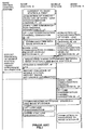
- FIG.1 is a processing sequence diagram for handover in a spread spectrum communication system (portable telephone system) based on the conventional CDMA-FDD (Code Divisional Multiple Access-Frequency Divisional Duplex) system.
- Symbols f1 and C0, etc. in FIG.1 denote carrier frequency number 1 and spreading code number 0, etc. Since the intention here is to facilitate expansion of base stations, the spreading code timing and frame timing are asynchronous between base stations. Furthermore, continuos transmit/receive operations are carried out by taking prevention of interference with hearing aids into account.
- the mobile station first calls base station A using carrier frequency number 1 for the down-link, and carrier frequency number 2 for the up-link. Then, the mobile station carries out handover to base station B and enters into communication using carrier frequency number 3 for the down-link, and carrier frequency number 4 for the up-link. The operation during handover between base stations under this condition is explained below.
- the mobile station acquires synchronization of a spreading code and frame for down-link synchronization channel (f1, c0) of base station A first.
- the mobile station then connects down-link communication channel (f1, c1) and up-link communication channel (f2, c2) in that order with base station A to enter into communication with base station A.
- the mobile station While communicating with base station A, the mobile station acquires synchronization of a spreading code and frame for down-link synchronization channel of carrier frequency number 3 of base station B (f3, c3) at the same time.
- the mobile station measures the receive level of both base station A and base station B and measures the timing difference between base station A and base station B at the same time.
- the mobile station issues a handover request to base station A. At this time, it also reports the information of said timing difference to base station A.
- Base station A reports the handover request received from the mobile station and the timing difference information to base station B via a base station control system.
- Base station B starts preparations for receiving the mobile station and a down-link communication channel directed to the mobile station is transmitted using carrier frequency number 3.
- the mobile station While maintaining the connection with base station A, the mobile station connects the down-link (f3, c5) and the up-link (f4, c6) of channels for communication with base station B. After a communication channel with base station B is established, the mobile station breaks connection with base station A. That completes handover.
- a mobile station In a portable telephone system based on the conventional CDMA-FDD system, when a mobile station carries out handover to a base station with a carrier frequency different from that of the base station with which it is currently communicating, it must transmit/receive two channels with different carrier frequencies simultaneously. Therefore, the mobile station must be provided with 2 lines of transmit/receive circuits, which entails the problem of increasing both the hardware size of the mobile station and power consumption.
- the object of the present invention is to provide a spread spectrum communication system in which a mobile station need not transmit/receive two or more carrier frequencies simultaneously when carrying out handover to a base station with a different frequency.
- This object is achieved a spread spectrum communication system in based on the CDMA-FDD system using a plurality of carrier frequencies selectively in which the spreading code timing and frame timing are asynchronous between base stations, including means for carrying out handover to the base station with the same carrier frequency while carrying out handover to a base station with a different carrier frequency and means for switching carrier frequencies within the handover base station after handover between these base stations.
- this configuration eliminates the necessity of the mobile station transmitting/receiving channels with two or more carrier frequencies simultaneously, allowing the hardware size of the mobile station to be reduced.
- the first mode of the present invention in a spread spectrum communication system based on the CDMA-FDD system that allows a plurality of carrier frequencies to be selectively used is equipped with the section that carries out handover between base stations with the same carrier frequency switched by a spreading code from a carrier frequency used for communication in progress, and the section that switches carrier frequencies within the handover base station after handover between those base stations is completed. This allows the mobile station to carry out handover between base stations with different frequencies without the mobile station transmitting/receiving two or more carrier frequencies simultaneously.
- the second mode of the present invention in the spread spectrum communication system based on the CDMA-FDD system that allows a plurality of carrier frequencies to be selectively used, is equipped with the section that switches from a normal communication carrier frequency to a specific carrier frequency for handover between base stations, the section that carries out handover between base stations with the same carrier frequency switched by a spreading code from said specific carrier frequency, and the section that switches from said specific carrier frequency to a normal communication carrier frequency within the handover base station after handover between these base stations is completed.
- This allows the mobile station to carry out handover between base stations with different frequencies without the mobile station transmitting/receiving two or more carrier frequencies simultaneously.
- handover is carried out at a specific carrier frequency by securing a space in the communication line with several carrier frequencies, handover is easily achieved.
- the third mode of the present invention in a portable telephone system based on the CDMA-FDD system, switches the carrier frequency within the handover base station when carrying out handover between cells with different carrier frequencies, and then carries out handover between base stations at the same carrier frequency. This allows the mobile station to flexibly realize handover between base stations with different carrier frequencies without the mobile station transmitting/receiving two or more carrier frequencies simultaneously.
- Embodiment 1 of the present invention describes a spread spectrum communication system equipped with the section that carries out handover between base stations at the same carrier frequency and the section that switches carrier frequencies within the handover base station.
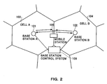
- FIG.2 is a drawing to explain handover between base stations in a spread spectrum communication system based on the CDMA-FDD system (portable telephone system) .
- mobile station 105 is communicating with base station A 101 in cell A 103 and move to cell B 104 to carry out handover to base station B 102.
- Base station A 101 and base station B 102 are controlled by base station control system 106.
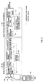
- base stations (BS) 101 and 102 are equipped with transmit/receive amplification section (AMP) 110, radio section (TRX) 111 that extracts a baseband signal from the carrier, baseband signal processing section (BB) 113 that obtains data from the baseband signal, transmission path interface section (HW-INT) 114, and control section (BS-CNT) 112 that controls the entire system.
- AMP transmit/receive amplification section
- TRX radio section
- BB baseband signal processing section
- HW-INT transmission path interface section
- BS-CNT control section
- Base station control system (MCC) 106 that controls base stations BS 101 and 102 is equipped with transmission path interface section 115, switch section (SW) 116 that carries out handover between base stations, external I/F section (EXT/INT) 117, and radio control/exchange control section (MCC-CNT) 118.
- MCC Base station control system
- SW switch section
- EXT/INT external I/F section
- EXT/INT radio control/exchange control section
- MCC-CNT radio control/exchange control section
- FIG.4 is a block diagram showing the configuration of mobile station 105 that communicates with base stations 101 and 102.
- this mobile station 105 receives a signal from antenna 120, it amplifies the signal with amplifier 121 and sends it to down-converter 122. After the carrier is eliminated by down-converter 122, the receive signal is divided into channel I and channel Q, and detected each by quasi-coherent demodulation section 123. Then, their respective channel signals are passed through LPF (Low Pass Filter) and converted from analog to digital by A/D converter 125.
- LPF Low Pass Filter
- the signal converted from analog to digital is divided into two systems and their correlative values are obtained by correlators 126 and 128, and synchronization is detected by synchronization detectors 127 and 129.
- the A/D-converted signal is sent to correlators 126 and 128 via delay section 130. These signals are further sent to receive SIR measuring section 131 that calculates their receive SIR which is the receive quality and also sent to soft handover composing section 132.
- the receive SIR measurement result is sent to control section 133 and control section 133 instructs synthesizer 134 to switch the carrier frequency according to the measurement result.
- Synthesizer 134 sends the switched carrier frequency to down-converter 122, quasi-coherent demodulation section 123, and quadrature modulation section 140 and up-converter 141 which will be described later.
- the transmit signal is frame-assembled by frame assembly section 135, modulated by modulator 136 and then spread through a spreading code by spread section 137. Then, the spread signal is passed through transmit filter 138, D/A-converted by D/A converter 139 and quadrature-modulated by quadrature modulation section 140. This quadrature-modulated transmit signal is carried by up-converter 141 onto a carrier, amplified by amplifier 142 and then transmitted from antenna 120.
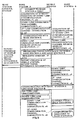
- FIG.5 is a processing sequence diagram in the case of handover of the spread spectrum communication system (portable telephone system) based on the CDMA-FDD system in Embodiment 1 of the present invention.
- FIG.6 is a flowchart of the operation of the mobile station in said spread spectrum communication system. Symbols f1 and c0, etc. in FIG.5 indicate carrier frequency number 1 and spreading code number 0, etc. Since the intention here is to expand base stations, the spreading code timing and frame timing are asynchronous between base stations. Furthermore, continuous transmit/receive operations are carried out by taking prevention of interference with hearing aids into account.
- the mobile station communicates with base station A by carrier frequency number 1 for the down-link, and by carrier frequency number 2 for the up-link first. Then, the mobile station carries out handover to base station B and communicates by carrier frequency number 3 for the down-link and by carrier frequency number 4 for the up-link.
- the mobile station acquires synchronization of a spreading code and frame for the down-link synchronization channel (f1, c0) of base station A first (ST 101). Then, the mobile station connects with base station A by down-link communication channel (f1, c1) and up-link communication channel (f2, c2) in that order, entering into communication with base station A (ST 102, 103). The mobile station acquires synchronization of a spreading code and frame (ST 105) for the down-link synchronization channel (f1, c3) of base station B while communicating with base station A (ST 104).
- the down-link synchronization channel has been transmitted with all carrier frequency numbers, and therefore the mobile station needs only to acquire synchronization for the down-link synchronization channel with the same carrier frequency number as that of the currently communicating channel. It need not receive channels with two carrier frequencies simultaneously.
- the mobile station After the mobile station acquires synchronization with base station B, it measures the receive level of both base station A and base station B (ST 106, 107) and at the same time measures the timing difference between base station A and base station B (ST 108). If receive level b of base station B is greater than receive level a of base station A currently in communication (ST 109), the mobile station issues a handover request to base station A and at this time it also reports the information of said timing difference to base station A (ST 110). If receive level b of base station B is smaller than receive level a of base station A, the mobile station continues communication with base station A.
- Base station A reports the handover request and timing difference information received from the mobile station to base station B via the base station control system.
- Base station B starts preparations for receiving the mobile station and sends the down-link communication channel (f1, c4) to the mobile station.
- the mobile station connects the down-link line (f1, c4) with the up-link line (f2, c2) of the communication channel with base station B while maintaining connection with base station A (ST 111, 112).
- base station B uses said timing difference information to adjust the timing of receiving the down-link communication channel from base station B at the mobile station to match the timing of receiving the down-link communication channel from base station A at the mobile station.
- a timing error remains because of a difference between the distance between the mobile station and base station A and the distance between the mobile station and base station B. Therefore, the mobile station needs to search the receive timing within the range of said timing error to acquire correct receive timing of the down-link communication channel (f1, c4) from base station B.
- base station B uses said timing difference information to acquire the receive timing of the up-link communication channel (f2, c2) transmitted from the mobile station. Since a timing error also remains because of a difference between the distance between the mobile station and base station A and the distance between the mobile station and base station B, base station B needs to search the up-link receive timing within the range of said timing error to acquire the correct receive timing of the up-link communication channel (f2, c2) from the mobile station.
- the down-link communication channel (f1, c4) transmitted from base station B to the mobile station has the same carrier frequency number as that of the down-link communication channel (f1, c1) transmitted from base station A to the mobile station with the only difference of the spreading code number. Therefore, the mobile station need not receive channels with two carrier frequencies simultaneously even when the mobile station connects communication channels to both base station A and base station B simultaneously. Furthermore, the up-link communication channel (f2, c2) has the same carrier frequency numbers, spreading code numbers, spreading code timings, frame timings, and transmit information for base station A and base station B.
- the connection with base station A is disconnected (ST 114, ST 115).
- the up-link and down-link carrier frequencies are switched simultaneously to number 4 and number 3, respectively (ST 116).
- the spreading code timing and frame timing remain unchanged, and therefore the mobile station and base station can switch carrier frequencies simultaneously.
- the time in which the communication channel is instantaneously disconnected due to a change of the carrier frequency number is determined by the performance of the frequency synthesizer and can be suppressed to within several microseconds. At this time, the spreading code number is also changed if necessary. That completes handover to base station B (ST 117).
- the mobile station can carry out handover between base stations with different carrier frequencies with a short instantaneous disconnection period without the mobile station having the function of transmitting/receiving channels with two carrier frequencies simultaneously.
- the Embodiment 2 of the present invention describes a spread spectrum communication system equipped with the section that switches from a normal communication carrier frequency to a specific carrier frequency for handover between base stations, the section that carries out handover between base stations with the same carrier frequency which is switched by a spreading code from a specific carrier frequency, and the section that switches from said specific carrier frequency to a normal communication carrier frequency within the handover base station.
- FIG.7 is a processing sequence diagram of the spread spectrum communication system (portable telephone system) based on the CDMA-FDD system in Embodiment 2 of the present invention in the case of handover.
- FIG.8 is a flowchart of the operation of a mobile station in said spread spectrum communication system. Symbols such as f1 and c0 in FIG. 7 indicate carrier frequency number 1 and spreading code number 0, etc. Since the intention here is to facilitate expansions of base stations, the spreading code timing and frame timing are asynchronous between base stations. Furthermore, continuos transmit/receive operations are carried out by taking prevention of interference with hearing aids into account.
- the mobile station communicates with base station A using carrier frequency number 1 for the down-link and carrier frequency number 2 for the up-link first. Then, the mobile station carries out handover to base station B and then enters into communication using carrier frequency number 3 for the down-link and carrier frequency number 4 for the up-link.
- the mobile station acquires synchronization of a spreading code and frame for down-link synchronization channel (f1, c0) of base station A first (ST 201).
- the mobile station then connects down-link communication channel (f1, c1) and up-link communication channel (f2, c2) in that order with base station A to enter into communication with base station A (ST 202, 203).
- the mobile station While communicating with base station A (ST 204), the mobile station acquires synchronization of a spreading code and frame (ST 205) for down-link synchronization channel (f1, c3) of base station B at the same time.
- the down-link synchronization channel has been transmitted with all carrier frequency numbers, and therefore the mobile station needs only to acquire synchronization for the down-link synchronization channel with the same carrier frequency number as that of the currently communicating channel. It need not receive channels with two carrier frequencies simultaneously.
- the mobile station After the mobile station acquires synchronization with base station B, it measures the receive level of both base station A and base station B (ST 206, 207) and at the same time measures the timing difference between base station A and base station B (ST 208). If receive level b of base station B is greater than receive level a of base station A currently in communication (ST 209), the mobile station issues a handover request to base station A and at this time it also reports the information of said timing difference to base station A (ST 210). If receive level b of base station B is smaller than receive level a of base station A, the mobile station continues communication with base station A.
- Base station A reports the handover request and timing difference information received from the mobile station to base station B via the base station control system.
- Base station B starts preparations for receiving the mobile station.
- the up-link and down-link carrier frequencies are simultaneously switched to number 9 and number 8, respectively (ST 211).
- number 9 on the up-link line and number 8 on the down-link line should be the numbers corresponding to the specific carrier frequencies used only for handover.
- the spreading code timing and frame timing are unchanged, the carrier frequencies can be changed at the mobile station and base station simultaneously.
- the time in which the communication channel is instantaneously disconnected due to a change of the carrier frequency number is determined by the performance of the frequency synthesizer and can be suppressed to within several microseconds. At this time, the spreading code number is also changed if necessary.
- a down-link communication channel (f8, c7) is transmitted from base station B to the mobile station.
- the up-link and down-link carrier frequency numbers used are number 9 and number 8 respectively.
- the spreading code number of the down-link communication channel should be set to a number different from that sent from base station A.
- the mobile station While maintaining the connection with base station A, the mobile station connects the down-link (f8, c7) and the up-link (f9, c9) of channels for communication with base station B (ST 212, 213).
- base station B uses said timing difference information to adjust the timing of receiving the down-link communication channel from base station B at the mobile station to match the timing of receiving the down-link communication channel from base station A at the mobile station.
- a timing error remains because of a difference between the distance between the mobile station and base station A and the distance between the mobile station and base station B. Therefore, the mobile station needs to search the receive timing within the range of said timing error to acquire correct receive timing of the down-link communication channel (f8, c7) from base station B.
- Base station B uses said timing difference information to acquire the receive timing of the up-link communication channel (f9, c9) transmitted from the mobile station. Since a timing error also remains because of a difference between the distance between the mobile station and base station A and the distance between the mobile station and base station B at this time, base station B needs to search the up-link receive timing within the range of said timing error to acquire the correct receive timing of the up-link communication channel from the mobile station.
- the down-link communication channel (f8, c7) transmitted from base station B to the mobile station has the same carrier frequency number as that of the down-link communication channel (f8, c8) transmitted from base station A to the mobile station with the only difference of the spreading code number. Therefore, the mobile station need not receive channels of two carrier frequencies simultaneously even when the mobile station connects communication channels to both base station A and base station B simultaneously. Furthermore, the up-link communication channel (f9, c9) has the same carrier frequency numbers, spreading code numbers, spreading code timings, frame timings, and transmit information for base station A and base station B.
- the connection with base station A is disconnected (ST 215, ST 216).
- the up-link and down-link carrier frequencies are switched simultaneously to number 4 and number 3, respectively (ST 217).
- the spreading code timing and frame timing remain unchanged, and therefore the mobile station and base station can switch carrier frequencies simultaneously.
- the time in which the communication channel is instantaneously disconnected due to a change of the carrier frequency number is determined by the performance of the frequency synthesizer and can be suppressed to within several microseconds. At this time, the spreading code number is also changed. That completes handover to base station B (ST 218).
- the provision of the section that carries out handover between base stations at a specific carrier frequency can reduce carrier frequencies for handover between base stations, achieving a spread spectrum communication system based on the CDMA-FDD system with high line utilization at base stations.
- FIG.9 is a processing sequence diagram of the spread spectrum communication system (portable telephone system) based on the CDMA-FDD system in Embodiment 3 of the present invention in the case of handover.
- FIG.10 is a flowchart of the operation of a mobile station in said spread spectrum communication system. Symbols such as f1 and c0 in FIG.9 indicate carrier frequency number 1 and spreading code number 0, etc. Since the intention here is to facilitate expansions of base stations, the spreading code timing and frame timing are asynchronous between base stations. Furthermore, continuos transmit/receive operations are carried out by taking prevention of interference with hearing aids into account.
- the mobile station communicates with base station A using carrier frequency number 1 for the down-link and carrier frequency number 2 for the up-link first. Then, the mobile station carries out handover to base station B and then enters into communication using carrier frequency number 3 for the down-link and carrier frequency number 4 for the up-link.
- the mobile station acquires synchronization of a spreading code and frame for down-link synchronization channel (f1, c0) of base station A first (ST 301).
- the mobile station then connects down-link communication channel (f1, c1) and up-link communication channel (f2, c2) in that order with base station A to enter into communication with base station A (ST 302, 303).
- the mobile station While communicating with base station A (ST 304), the mobile station acquires synchronization of a spreading code and frame for down-link synchronization channel (f1, c3) of base station B at the same time (ST 305).
- the down-link synchronization channel has been transmitted with all carrier frequency numbers, and therefore the mobile station needs only to acquire synchronization for the down-link synchronization channel with the same carrier frequency number as that of the communication channel currently in communication. It need not receive channels with two carrier frequencies simultaneously.
- the mobile station After the mobile station acquires synchronization with base station B, it measures the receive level of both base station A and base station B (ST 306, 307) and at the same time measures the timing difference between base station A and base station B (ST 308). If receive level b of base station B is greater than receive level a of base station A currently in communication (ST 309), the mobile station issues a handover request to base station A and at this time it also reports the information of said timing difference to base station A (ST 310). If receive level b of base station B is smaller than receive level a of base station A, the mobile station continues communication with base station A.
- Base station A reports the handover request and timing difference information received from the mobile station to base station B via the base station control system.
- Base station B starts preparations for receiving the mobile station.
- the up-link and down-link carrier frequencies are simultaneously switched to number 3 and number 4, respectively (ST 311).
- the carrier frequencies can be changed at the mobile station and base station simultaneously.
- the time in which the communication channel is instantaneously disconnected due to a change of the carrier frequency number is determined by the performance of the frequency synthesizer and can be suppressed to within several microseconds. At this time, the spreading code number is also changed if necessary.
- a down-link communication channel is transmitted from base station B to the mobile station.
- the up-link and down-link carrier frequency numbers used are number 3 and number 4 respectively.
- the spreading code number of the down-link communication channel should be a number different from that sent from base station A.
- the mobile station While maintaining the connection with base station A, the mobile station connects the down-link and the up-link of channels for communication with base station B (ST 312, 313).
- base station B uses said timing difference information to adjust the timing of receiving the down-link communication channel from base station B at the mobile station to match the timing for receiving the down-link communication channel from base station A at the mobile station.
- a timing error remains because of a difference between the distance between the mobile station and base station A and the distance between the mobile station and base station B. Therefore, the mobile station needs to search the receive timing within the range of said timing error to acquire correct receive timing of the down-link communication channel from base station B.
- Base station B uses said timing difference information to acquire the receive timing of the up-link communication channel transmitted from the mobile station. Since a timing error also remains at this time because of a difference between the distance between the mobile station and base station A and the distance between the mobile station and base station B, base station B needs to search the up-link receive timing within the range of said timing error to acquire the correct receive timing of the up-link communication channel from the mobile station.
- the down-link communication channel transmitted from base station B to the mobile station has the same carrier frequency number as that of the down-link communication channel transmitted from base station A to the mobile station with the only difference of the spreading code number. Therefore, the mobile station need not receive two carriers simultaneously even when the mobile station connects communication channels to both base station A and base station B simultaneously. Furthermore, the up-link communication channel has the same carrier frequency numbers, spreading code numbers, spreading code timings, frame timings, and transmit information for base station A and base station B.
- the mobile station can carry out handover between base stations with different carrier frequencies in a short instantaneous disconnection period without the mobile station having the function of transmitting/receiving two carrier frequencies simultaneously.
- the present invention eliminates the necessity of the mobile station transmitting/receiving two or more carrier frequencies simultaneously and makes it possible to flexibly use a plurality of carrier frequencies.
- the present invention needs only to secure free communication lines to receive mobile stations that move into cells by carrying out handover between base stations for several carrier frequencies, achieving high line utilization at base stations.
- the signals transmitted/received in the system of present invention contain pilot symbol per user in up-link and down-link.
Landscapes
- Engineering & Computer Science (AREA)
- Computer Networks & Wireless Communication (AREA)
- Signal Processing (AREA)
- Mobile Radio Communication Systems (AREA)
Applications Claiming Priority (3)
| Application Number | Priority Date | Filing Date | Title |
|---|---|---|---|
| JP11174897 | 1997-04-15 | ||
| JP11174897 | 1997-04-15 | ||
| EP98106758A EP0873034B1 (fr) | 1997-04-15 | 1998-04-14 | Procédé de transfert d'appel dans un système de communication à étalement de spectre |
Related Parent Applications (2)
| Application Number | Title | Priority Date | Filing Date |
|---|---|---|---|
| EP98106758A Division-Into EP0873034B1 (fr) | 1997-04-15 | 1998-04-14 | Procédé de transfert d'appel dans un système de communication à étalement de spectre |
| EP98106758A Division EP0873034B1 (fr) | 1997-04-15 | 1998-04-14 | Procédé de transfert d'appel dans un système de communication à étalement de spectre |
Publications (2)
| Publication Number | Publication Date |
|---|---|
| EP1304899A1 true EP1304899A1 (fr) | 2003-04-23 |
| EP1304899B1 EP1304899B1 (fr) | 2004-05-19 |
Family
ID=14569194
Family Applications (2)
| Application Number | Title | Priority Date | Filing Date |
|---|---|---|---|
| EP02026952A Expired - Lifetime EP1304899B1 (fr) | 1997-04-15 | 1998-04-14 | Système de communication à étalement de spectre |
| EP98106758A Expired - Lifetime EP0873034B1 (fr) | 1997-04-15 | 1998-04-14 | Procédé de transfert d'appel dans un système de communication à étalement de spectre |
Family Applications After (1)
| Application Number | Title | Priority Date | Filing Date |
|---|---|---|---|
| EP98106758A Expired - Lifetime EP0873034B1 (fr) | 1997-04-15 | 1998-04-14 | Procédé de transfert d'appel dans un système de communication à étalement de spectre |
Country Status (5)
| Country | Link |
|---|---|
| US (1) | US6628630B1 (fr) |
| EP (2) | EP1304899B1 (fr) |
| KR (2) | KR100360945B1 (fr) |
| CN (2) | CN1086524C (fr) |
| DE (2) | DE69824054T2 (fr) |
Cited By (1)
| Publication number | Priority date | Publication date | Assignee | Title |
|---|---|---|---|---|
| GB2463009A (en) * | 2008-08-26 | 2010-03-03 | Nomad Spectrum Ltd | Providing data communication to a moving vehicle |
Families Citing this family (35)
| Publication number | Priority date | Publication date | Assignee | Title |
|---|---|---|---|---|
| US7787647B2 (en) | 1997-01-13 | 2010-08-31 | Micro Ear Technology, Inc. | Portable system for programming hearing aids |
| JP2945357B2 (ja) * | 1997-07-19 | 1999-09-06 | 松下電器産業株式会社 | Cdma方式の移動局装置及び制御局装置 |
| KR100547838B1 (ko) * | 1998-11-17 | 2006-03-23 | 삼성전자주식회사 | 부호분할다중접속 통신시스템에서 전용제어채널의 핸드오프방법 |
| DE19900436B4 (de) * | 1999-01-08 | 2016-12-01 | Ipcom Gmbh & Co. Kg | Verfahren zum Handover, Mobilstation für ein Handover und Basisstation für ein Handover |
| MXPA01008595A (es) | 1999-02-26 | 2002-03-14 | Qualcomm Inc | Metodo y sistema para conexion entre una estacion base cdma de asincronia y una estacion base cdma de sincronia. |
| USRE47895E1 (en) | 1999-03-08 | 2020-03-03 | Ipcom Gmbh & Co. Kg | Method of allocating access rights to a telecommunications channel to subscriber stations of a telecommunications network and subscriber station |
| SE514049C2 (sv) * | 1999-03-24 | 2000-12-18 | Teracom Ab | Metod för testmottagning av alternativa mottagningsfrekvenser |
| US6788665B1 (en) * | 1999-10-06 | 2004-09-07 | Utstarcom, Inc. | Method and apparatus using alternate frames for handover in TDMA mobile communications system |
| WO2001054458A2 (fr) | 2000-01-20 | 2001-07-26 | Starkey Laboratories, Inc. | Systemes pour protheses auditives |
| JP3382922B2 (ja) * | 2000-07-06 | 2003-03-04 | 埼玉日本電気株式会社 | 移動通信システム、移動機、交換機及び移動通信方法 |
| US6961304B1 (en) * | 2000-09-12 | 2005-11-01 | Lucent Technologies Inc. | Dynamic reassignment of code space among multiple modes of operation |
| JP2002176666A (ja) * | 2000-12-05 | 2002-06-21 | Sony Corp | 移動通信システム |
| TWI222814B (en) * | 2001-08-14 | 2004-10-21 | Flarion Technologies Inc | Methods and apparatus for wireless network connectivity |
| US7408900B2 (en) | 2002-06-28 | 2008-08-05 | Interdigital Technology Corporation | Method and system for automated determination of inter-system border thresholds |
| JP2004236294A (ja) * | 2003-01-10 | 2004-08-19 | Matsushita Electric Ind Co Ltd | 通信網制御装置及びその方法 |
| KR100665425B1 (ko) * | 2003-03-08 | 2007-01-04 | 삼성전자주식회사 | 이동 통신 시스템에서 핸드오버를 수행하는 시스템 및 방법 |
| CN101048011B (zh) * | 2006-06-20 | 2011-01-05 | 华为技术有限公司 | 下行双/多载传输下进行分组交换业务切换的方法 |
| US8917673B2 (en) * | 2006-07-14 | 2014-12-23 | Qualcomm Incorporation | Configurable downlink and uplink channels for improving transmission of data by switching duplex nominal frequency spacing according to conditions |
| CA2601662A1 (fr) | 2006-09-18 | 2008-03-18 | Matthias Mullenborn | Interface sans fil pour programmer des dispositifs d'aide auditive |
| GB2449231B (en) * | 2007-04-25 | 2012-01-04 | Motorola Mobility Inc | A cellular communication system and method of operation thereof |
| KR101559320B1 (ko) * | 2008-02-18 | 2015-10-13 | 삼성전자주식회사 | 라이센스 대역 및 공유 대역의 효과적 사용을 위한 모바일시스템 및 기지국 시스템 |
| US8676208B2 (en) * | 2008-06-11 | 2014-03-18 | Mediatek Inc. | Scanning and handover operation in multi-carrier wireless communications systems |
| US9204349B2 (en) | 2009-02-10 | 2015-12-01 | Qualcomm Incorporated | Method and apparatus for facilitating a hand-in of user equipment to femto cells |
| EP2422544A4 (fr) * | 2009-04-24 | 2016-01-06 | Mediatek Inc | Attribution de porteuse avec prise en charge de mobilité dans des systèmes ofdm multi-porteuses |
| US9332464B2 (en) * | 2009-06-19 | 2016-05-03 | Qualcomm Incorporated | Method and apparatus that facilitates measurement procedures in multicarrier operation |
| US9392562B2 (en) | 2009-11-17 | 2016-07-12 | Qualcomm Incorporated | Idle access terminal-assisted time and/or frequency tracking |
| US9642105B2 (en) | 2009-11-17 | 2017-05-02 | Qualcomm Incorporated | Access terminal-assisted time and/or frequency tracking |
| US9271248B2 (en) | 2010-03-02 | 2016-02-23 | Qualcomm Incorporated | System and method for timing and frequency synchronization by a Femto access point |
| US9049630B2 (en) * | 2010-04-01 | 2015-06-02 | Qualcomm Incorporated | Facilitating baton handover in multi-carrier TD-SCDMA communications systems |
| CN102083097B (zh) * | 2010-04-30 | 2013-11-06 | 电信科学技术研究院 | 多载波系统的测量配置方法及其装置 |
| US9756553B2 (en) | 2010-09-16 | 2017-09-05 | Qualcomm Incorporated | System and method for assisted network acquisition and search updates |
| CN102026264B (zh) * | 2010-12-17 | 2013-10-16 | 大唐移动通信设备有限公司 | 一种终端测量上报和系统间互操作方法及设备 |
| US8688127B1 (en) | 2011-03-16 | 2014-04-01 | Sprint Spectrum L.P. | Method and system for inter-frequency handoff |
| US9155057B2 (en) | 2012-05-01 | 2015-10-06 | Qualcomm Incorporated | Femtocell synchronization enhancements using access probes from cooperating mobiles |
| US9237530B2 (en) | 2012-11-09 | 2016-01-12 | Qualcomm Incorporated | Network listen with self interference cancellation |
Citations (3)
| Publication number | Priority date | Publication date | Assignee | Title |
|---|---|---|---|---|
| EP0680160A2 (fr) * | 1994-04-27 | 1995-11-02 | Ntt Mobile Communications Network Inc. | Procédé et dispositif de contrôle de la puissance de transmission d'une station mobile pendant une commutation douce dans un système à accès multiple par division de code |
| WO1996002117A2 (fr) * | 1994-07-11 | 1996-01-25 | Nokia Telecommunications Oy | Procede de commutation et systeme de communication cellulaire |
| WO1997008910A1 (fr) * | 1995-08-31 | 1997-03-06 | Nokia Telecommunications Oy | Procede de selection de la maniere d'effectuer un transfert et systeme de radiocommunications cellulaire |
Family Cites Families (31)
| Publication number | Priority date | Publication date | Assignee | Title |
|---|---|---|---|---|
| FI96157C (fi) * | 1992-04-27 | 1996-05-10 | Nokia Mobile Phones Ltd | Digitaalinen, solukkorakenteinen aikajakokanavointiin perustuva radiopuhelinverkko radioyhteyden siirtämiseksi tukiasemalta uudelle tukiasemalle |
| US5392452A (en) * | 1992-11-27 | 1995-02-21 | Motorola, Inc. | Selective call signaling system with combined wide area paging and high data rate transmissions via radio telephone transceivers |
| CA2111807C (fr) | 1992-12-24 | 1999-08-17 | Hitoshi Takai | Appareil de transmission et de reception de donnees |
| JP2924536B2 (ja) | 1993-01-14 | 1999-07-26 | ケイディディ株式会社 | スペクトル拡散通信システムにおけるソフトハンドオフ方法 |
| GB2280335B (en) * | 1993-07-22 | 1997-05-28 | Northern Telecom Ltd | Mobile communications |
| FI110043B (fi) * | 1993-09-20 | 2002-11-15 | Nokia Corp | Menetelmä kanavanvaihdon suorittamiseksi CDMA-solukkoradiojärjestelmässä sekä liikkuva asema |
| JP3003839B2 (ja) * | 1993-11-08 | 2000-01-31 | エヌ・ティ・ティ移動通信網株式会社 | Cdma通信方法および装置 |
| KR960007664B1 (ko) | 1993-12-29 | 1996-06-08 | 재단법인 한국전자통신연구소 | 씨.디.엠.에이(cdma) 셀룰러 시스템의 핸드오프 결정 방법 |
| JP3305877B2 (ja) * | 1994-06-23 | 2002-07-24 | 株式会社東芝 | スペクトラム拡散無線通信システムおよびこのシステムで使用される無線通信装置 |
| US5564974A (en) * | 1994-09-06 | 1996-10-15 | Cummins-Allison Corp. | Coin sorting system with touch screen device |
| KR970008949B1 (en) * | 1994-11-16 | 1997-06-03 | Korea Electronics Telecomm | Method and system for providing a frequency handoff in communication in a cdma cellular telephone system |
| US6035197A (en) * | 1994-12-29 | 2000-03-07 | Cellco Partnership | Method and system for providing a handoff from a CDMA cellular telephone system |
| ATE263469T1 (de) * | 1995-08-31 | 2004-04-15 | Nokia Corp | Weiterreichverfahren und zellulares funksystem |
| US5794149A (en) * | 1995-12-29 | 1998-08-11 | Lucent Technologies Inc. | Base station controlled handoff method and apparatus |
| JP2803720B2 (ja) * | 1996-04-10 | 1998-09-24 | 日本電気株式会社 | Cdma移動通信システム用ハンドオフ制御方式 |
| US5926470A (en) * | 1996-05-22 | 1999-07-20 | Qualcomm Incorporated | Method and apparatus for providing diversity in hard handoff for a CDMA system |
| MY117945A (en) * | 1996-09-27 | 2004-08-30 | Nec Corp | Hand- off method and apparatus in cdma cellular system |
| JP2845228B2 (ja) * | 1996-12-10 | 1999-01-13 | 日本電気株式会社 | 隣接セル同期検出方式 |
| US5987326A (en) * | 1997-02-11 | 1999-11-16 | Qualcomm Incorporated | Transmit power reduction for a high speed CDMA link in soft handoff |
| US5901145A (en) * | 1997-02-28 | 1999-05-04 | Telefonaktiebolaget L M Ericsson (Publ) | Mobile station handoff between a spread spectrum communications system and a frequency division communications system |
| JP3537988B2 (ja) | 1997-03-25 | 2004-06-14 | 松下電器産業株式会社 | 無線送信装置 |
| JP3432697B2 (ja) | 1997-04-02 | 2003-08-04 | 松下電器産業株式会社 | 適応受信ダイバーシチ装置及び適応送信ダイバーシチ装置 |
| JP3628145B2 (ja) | 1997-05-21 | 2005-03-09 | 松下電器産業株式会社 | 送信電力制御装置及び送信電力制御方法 |
| US5933112A (en) | 1997-05-30 | 1999-08-03 | Matsushita Electric Industrial Co., Ltd. | Antenna array receiver and a method of correcting a phase shift amount of a receiving signal |
| US6073021A (en) * | 1997-05-30 | 2000-06-06 | Lucent Technologies, Inc. | Robust CDMA soft handoff |
| JP3391662B2 (ja) | 1997-06-06 | 2003-03-31 | 松下電器産業株式会社 | アダプティブアレーアンテナ受信装置 |
| US5872774A (en) * | 1997-09-19 | 1999-02-16 | Qualcomm Incorporated | Mobile station assisted timing synchronization in a CDMA communication system |
| US6078571A (en) * | 1997-09-19 | 2000-06-20 | Motorola, Inc. | Apparatus and method for transmitting beacon signals in a communication system |
| JPH11145899A (ja) | 1997-11-10 | 1999-05-28 | Matsushita Electric Ind Co Ltd | 送受信装置及び無線伝送システム |
| US6075989A (en) * | 1998-01-20 | 2000-06-13 | Motorola, Inc. | Method and apparatus for determining a need to handoff a mobile communication signal in a wireless communication system |
| US5956641A (en) * | 1998-03-30 | 1999-09-21 | Motorola, Inc. | System and method for facilitating a handoff of at least one mobile unit in a telecommunication system |
-
1998
- 1998-04-13 US US09/058,881 patent/US6628630B1/en not_active Expired - Lifetime
- 1998-04-14 DE DE69824054T patent/DE69824054T2/de not_active Expired - Lifetime
- 1998-04-14 EP EP02026952A patent/EP1304899B1/fr not_active Expired - Lifetime
- 1998-04-14 DE DE69817904T patent/DE69817904T2/de not_active Expired - Lifetime
- 1998-04-14 EP EP98106758A patent/EP0873034B1/fr not_active Expired - Lifetime
- 1998-04-15 KR KR1019980013454A patent/KR100360945B1/ko not_active IP Right Cessation
- 1998-04-15 CN CN98106939A patent/CN1086524C/zh not_active Expired - Lifetime
- 1998-04-15 CN CNB021055769A patent/CN1170388C/zh not_active Expired - Lifetime
-
2002
- 2002-05-31 KR KR1020020030497A patent/KR100371837B1/ko not_active IP Right Cessation
Patent Citations (3)
| Publication number | Priority date | Publication date | Assignee | Title |
|---|---|---|---|---|
| EP0680160A2 (fr) * | 1994-04-27 | 1995-11-02 | Ntt Mobile Communications Network Inc. | Procédé et dispositif de contrôle de la puissance de transmission d'une station mobile pendant une commutation douce dans un système à accès multiple par division de code |
| WO1996002117A2 (fr) * | 1994-07-11 | 1996-01-25 | Nokia Telecommunications Oy | Procede de commutation et systeme de communication cellulaire |
| WO1997008910A1 (fr) * | 1995-08-31 | 1997-03-06 | Nokia Telecommunications Oy | Procede de selection de la maniere d'effectuer un transfert et systeme de radiocommunications cellulaire |
Cited By (4)
| Publication number | Priority date | Publication date | Assignee | Title |
|---|---|---|---|---|
| GB2463009A (en) * | 2008-08-26 | 2010-03-03 | Nomad Spectrum Ltd | Providing data communication to a moving vehicle |
| GB2462910A (en) * | 2008-08-26 | 2010-03-03 | Nomad Spectrum Ltd | Communication between a vehicle and two base stations |
| GB2462910B (en) * | 2008-08-26 | 2010-08-11 | Nomad Spectrum Ltd | Mobile data communication |
| GB2463009B (en) * | 2008-08-26 | 2010-12-08 | Nomad Spectrum Ltd | Mobile data communication |
Also Published As
| Publication number | Publication date |
|---|---|
| US6628630B1 (en) | 2003-09-30 |
| DE69824054T2 (de) | 2004-09-09 |
| KR100360945B1 (ko) | 2002-12-18 |
| CN1398079A (zh) | 2003-02-19 |
| KR19980081434A (ko) | 1998-11-25 |
| EP0873034A3 (fr) | 2001-12-05 |
| EP0873034B1 (fr) | 2003-09-10 |
| EP0873034A2 (fr) | 1998-10-21 |
| KR100371837B1 (ko) | 2003-02-12 |
| DE69817904T2 (de) | 2004-05-19 |
| CN1198054A (zh) | 1998-11-04 |
| DE69817904D1 (de) | 2003-10-16 |
| CN1170388C (zh) | 2004-10-06 |
| DE69824054D1 (de) | 2004-06-24 |
| EP1304899B1 (fr) | 2004-05-19 |
| CN1086524C (zh) | 2002-06-19 |
Similar Documents
| Publication | Publication Date | Title |
|---|---|---|
| EP1304899B1 (fr) | Système de communication à étalement de spectre | |
| KR100384189B1 (ko) | 다중주파수통신장치 | |
| JP3215018B2 (ja) | 移動通信システム | |
| KR100292318B1 (ko) | 이동통신기지국장치 | |
| US5970406A (en) | Translator for time division multiple access wireless system having selective diversity circuits | |
| EP0652644B1 (fr) | Station émettrice-réceptrice de base pour système cellulaire | |
| KR20040004261A (ko) | 시분할 복신 중계 방법 및 장치 | |
| EP0991204A2 (fr) | Procédé de commande de la puissance de transmission avec une configuration de symboles pilotes | |
| JP3094221B2 (ja) | コード分割多重方式基地局用の周期型ビーコン信号発生装置 | |
| JPH114211A (ja) | スペクトル拡散通信システム | |
| KR20050076886A (ko) | 비동기 시스템에서 주파수간 하드 핸드오버를 지원하기위한 공통채널 비콘 신호 송신 방법 및 장치. | |
| KR100204954B1 (ko) | 주파수간 하드 핸드오버를 원활하게 수행하는 파일롯 비콘 | |
| KR100266868B1 (ko) | 코드분할다중접속기지국시스템의파일럿송신기 | |
| JPH10163958A (ja) | 移動体通信基地局システム | |
| KR100283076B1 (ko) | 코드분할다중접속 방식의 원격지 기지국을 운용하는 도너 기지국 | |
| KR100586230B1 (ko) | 파일럿 비콘 장치와 이를 이용한 핸드오프 신호 발생 방법 | |
| CA2200960C (fr) | Radio multibande | |
| KR100248263B1 (ko) | 도시용 씨디엠에이 소형 기지국에 사용하는 주파수 확장장치 | |
| KR100321481B1 (ko) | 공간파 유기를 이용한 이동전화망에서의 가상주파수 변환 발생기 | |
| KR100283223B1 (ko) | 이동 통신 시스템용 순방향 전송 방법 및 그 장치 | |
| JPH1169414A (ja) | 無線機 | |
| KR100404879B1 (ko) | 이동 통신망에서 소형 기지국 | |
| Miura et al. | Centralized control method for fiber-optic microcell radio system |
Legal Events
| Date | Code | Title | Description |
|---|---|---|---|
| PUAI | Public reference made under article 153(3) epc to a published international application that has entered the european phase |
Free format text: ORIGINAL CODE: 0009012 |
|
| 17P | Request for examination filed |
Effective date: 20021204 |
|
| AC | Divisional application: reference to earlier application |
Ref document number: 0873034 Country of ref document: EP Kind code of ref document: P |
|
| AK | Designated contracting states |
Designated state(s): DE FR GB NL SE |
|
| RIN1 | Information on inventor provided before grant (corrected) |
Inventor name: NAGASE, TAKU |
|
| 17Q | First examination report despatched |
Effective date: 20030611 |
|
| GRAP | Despatch of communication of intention to grant a patent |
Free format text: ORIGINAL CODE: EPIDOSNIGR1 |
|
| AKX | Designation fees paid |
Designated state(s): DE FR GB NL SE |
|
| GRAS | Grant fee paid |
Free format text: ORIGINAL CODE: EPIDOSNIGR3 |
|
| GRAA | (expected) grant |
Free format text: ORIGINAL CODE: 0009210 |
|
| AC | Divisional application: reference to earlier application |
Ref document number: 0873034 Country of ref document: EP Kind code of ref document: P |
|
| AK | Designated contracting states |
Kind code of ref document: B1 Designated state(s): DE FR GB NL SE |
|
| REG | Reference to a national code |
Ref country code: GB Ref legal event code: FG4D |
|
| REF | Corresponds to: |
Ref document number: 69824054 Country of ref document: DE Date of ref document: 20040624 Kind code of ref document: P |
|
| REG | Reference to a national code |
Ref country code: SE Ref legal event code: TRGR |
|
| ET | Fr: translation filed | ||
| PLBE | No opposition filed within time limit |
Free format text: ORIGINAL CODE: 0009261 |
|
| STAA | Information on the status of an ep patent application or granted ep patent |
Free format text: STATUS: NO OPPOSITION FILED WITHIN TIME LIMIT |
|
| 26N | No opposition filed |
Effective date: 20050222 |
|
| REG | Reference to a national code |
Ref country code: NL Ref legal event code: TD Effective date: 20131127 |
|
| REG | Reference to a national code |
Ref country code: FR Ref legal event code: CD Owner name: PANASONIC CORPORATION, JP Effective date: 20131217 |
|
| REG | Reference to a national code |
Ref country code: GB Ref legal event code: 732E Free format text: REGISTERED BETWEEN 20140925 AND 20141001 |
|
| REG | Reference to a national code |
Ref country code: GB Ref legal event code: 732E Free format text: REGISTERED BETWEEN 20150129 AND 20150204 |
|
| REG | Reference to a national code |
Ref country code: FR Ref legal event code: PLFP Year of fee payment: 18 |
|
| REG | Reference to a national code |
Ref country code: DE Ref legal event code: R079 Ref document number: 69824054 Country of ref document: DE Free format text: PREVIOUS MAIN CLASS: H04Q0007380000 Ipc: H04W0004000000 Ref country code: DE Ref legal event code: R082 Ref document number: 69824054 Country of ref document: DE Representative=s name: EISENFUEHR SPEISER PATENTANWAELTE RECHTSANWAEL, DE Ref country code: DE Ref legal event code: R081 Ref document number: 69824054 Country of ref document: DE Owner name: INVENTERGY, INC. (N.D.GES.D. STAATES DELAWARE), US Free format text: FORMER OWNER: PANASONIC CORPORATION, KADOMA-SHI, OSAKA, JP Ref country code: DE Ref legal event code: R081 Ref document number: 69824054 Country of ref document: DE Owner name: INVT SPE LLC (N.D.GES.D. STAATES DELAWARE), SA, US Free format text: FORMER OWNER: PANASONIC CORPORATION, KADOMA-SHI, OSAKA, JP |
|
| REG | Reference to a national code |
Ref country code: FR Ref legal event code: TP Owner name: INVENTERGY, INC., US Effective date: 20151027 |
|
| REG | Reference to a national code |
Ref country code: FR Ref legal event code: PLFP Year of fee payment: 19 |
|
| REG | Reference to a national code |
Ref country code: FR Ref legal event code: PLFP Year of fee payment: 20 |
|
| PGFP | Annual fee paid to national office [announced via postgrant information from national office to epo] |
Ref country code: NL Payment date: 20170320 Year of fee payment: 20 Ref country code: FR Payment date: 20170313 Year of fee payment: 20 |
|
| PGFP | Annual fee paid to national office [announced via postgrant information from national office to epo] |
Ref country code: DE Payment date: 20170411 Year of fee payment: 20 Ref country code: GB Payment date: 20170412 Year of fee payment: 20 |
|
| PGFP | Annual fee paid to national office [announced via postgrant information from national office to epo] |
Ref country code: SE Payment date: 20170411 Year of fee payment: 20 |
|
| REG | Reference to a national code |
Ref country code: DE Ref legal event code: R082 Ref document number: 69824054 Country of ref document: DE Representative=s name: EISENFUEHR SPEISER PATENTANWAELTE RECHTSANWAEL, DE Ref country code: DE Ref legal event code: R081 Ref document number: 69824054 Country of ref document: DE Owner name: INVT SPE LLC (N.D.GES.D. STAATES DELAWARE), SA, US Free format text: FORMER OWNER: INVENTERGY, INC. (N.D.GES.D. STAATES DELAWARE), CAMPBELL, CALIF., US |
|
| REG | Reference to a national code |
Ref country code: GB Ref legal event code: 732E Free format text: REGISTERED BETWEEN 20171214 AND 20171222 |
|
| REG | Reference to a national code |
Ref country code: FR Ref legal event code: TP Owner name: INVT SPE LLC, US Effective date: 20171018 |
|
| REG | Reference to a national code |
Ref country code: DE Ref legal event code: R071 Ref document number: 69824054 Country of ref document: DE |
|
| REG | Reference to a national code |
Ref country code: NL Ref legal event code: MK Effective date: 20180413 |
|
| REG | Reference to a national code |
Ref country code: GB Ref legal event code: PE20 Expiry date: 20180413 |
|
| REG | Reference to a national code |
Ref country code: SE Ref legal event code: EUG |
|
| PG25 | Lapsed in a contracting state [announced via postgrant information from national office to epo] |
Ref country code: GB Free format text: LAPSE BECAUSE OF EXPIRATION OF PROTECTION Effective date: 20180413 |