EP1304803B1 - Circuit logique programmable comprenant des transistors à silicium sur isolant - Google Patents
Circuit logique programmable comprenant des transistors à silicium sur isolant Download PDFInfo
- Publication number
- EP1304803B1 EP1304803B1 EP02022570A EP02022570A EP1304803B1 EP 1304803 B1 EP1304803 B1 EP 1304803B1 EP 02022570 A EP02022570 A EP 02022570A EP 02022570 A EP02022570 A EP 02022570A EP 1304803 B1 EP1304803 B1 EP 1304803B1
- Authority
- EP
- European Patent Office
- Prior art keywords
- transistor
- metal oxide
- oxide semiconductor
- pld
- programmable
- Prior art date
- Legal status (The legal status is an assumption and is not a legal conclusion. Google has not performed a legal analysis and makes no representation as to the accuracy of the status listed.)
- Expired - Fee Related
Links
- 239000012212 insulator Substances 0.000 title claims description 48
- 239000004065 semiconductor Substances 0.000 claims description 54
- 229910044991 metal oxide Inorganic materials 0.000 claims description 50
- 150000004706 metal oxides Chemical class 0.000 claims description 50
- 230000002093 peripheral effect Effects 0.000 claims description 39
- 238000012545 processing Methods 0.000 claims description 35
- 238000000034 method Methods 0.000 claims description 15
- 230000000295 complement effect Effects 0.000 claims description 2
- 238000004549 pulsed laser deposition Methods 0.000 description 50
- 230000008901 benefit Effects 0.000 description 32
- 210000000746 body region Anatomy 0.000 description 19
- VYPSYNLAJGMNEJ-UHFFFAOYSA-N Silicium dioxide Chemical compound O=[Si]=O VYPSYNLAJGMNEJ-UHFFFAOYSA-N 0.000 description 18
- 230000007423 decrease Effects 0.000 description 17
- 239000000758 substrate Substances 0.000 description 14
- 230000003071 parasitic effect Effects 0.000 description 9
- 239000000377 silicon dioxide Substances 0.000 description 9
- 230000008878 coupling Effects 0.000 description 8
- 238000010168 coupling process Methods 0.000 description 8
- 238000005859 coupling reaction Methods 0.000 description 8
- 230000004044 response Effects 0.000 description 7
- 235000012239 silicon dioxide Nutrition 0.000 description 6
- 230000003247 decreasing effect Effects 0.000 description 5
- 238000013461 design Methods 0.000 description 5
- 238000005516 engineering process Methods 0.000 description 5
- 230000005540 biological transmission Effects 0.000 description 4
- 238000004891 communication Methods 0.000 description 4
- 238000012986 modification Methods 0.000 description 4
- 230000004048 modification Effects 0.000 description 4
- XUIMIQQOPSSXEZ-UHFFFAOYSA-N Silicon Chemical compound [Si] XUIMIQQOPSSXEZ-UHFFFAOYSA-N 0.000 description 3
- 239000000872 buffer Substances 0.000 description 3
- 230000000694 effects Effects 0.000 description 3
- 239000004744 fabric Substances 0.000 description 3
- 238000004519 manufacturing process Methods 0.000 description 3
- 229910052710 silicon Inorganic materials 0.000 description 3
- 239000010703 silicon Substances 0.000 description 3
- 230000001154 acute effect Effects 0.000 description 2
- 230000005669 field effect Effects 0.000 description 2
- 230000006870 function Effects 0.000 description 2
- 239000000463 material Substances 0.000 description 2
- 229910052751 metal Inorganic materials 0.000 description 2
- 239000002184 metal Substances 0.000 description 2
- 229910021420 polycrystalline silicon Inorganic materials 0.000 description 2
- 229920005591 polysilicon Polymers 0.000 description 2
- 230000002441 reversible effect Effects 0.000 description 2
- 230000006399 behavior Effects 0.000 description 1
- 230000008859 change Effects 0.000 description 1
- 239000004020 conductor Substances 0.000 description 1
- 238000012937 correction Methods 0.000 description 1
- 238000001514 detection method Methods 0.000 description 1
- 150000002739 metals Chemical class 0.000 description 1
- 238000000926 separation method Methods 0.000 description 1
Images


Classifications
-
- H—ELECTRICITY
- H03—ELECTRONIC CIRCUITRY
- H03K—PULSE TECHNIQUE
- H03K19/00—Logic circuits, i.e. having at least two inputs acting on one output; Inverting circuits
- H03K19/02—Logic circuits, i.e. having at least two inputs acting on one output; Inverting circuits using specified components
- H03K19/173—Logic circuits, i.e. having at least two inputs acting on one output; Inverting circuits using specified components using elementary logic circuits as components
- H03K19/177—Logic circuits, i.e. having at least two inputs acting on one output; Inverting circuits using specified components using elementary logic circuits as components arranged in matrix form
- H03K19/1778—Structural details for adapting physical parameters
-
- H—ELECTRICITY
- H01—ELECTRIC ELEMENTS
- H01L—SEMICONDUCTOR DEVICES NOT COVERED BY CLASS H10
- H01L29/00—Semiconductor devices adapted for rectifying, amplifying, oscillating or switching, or capacitors or resistors with at least one potential-jump barrier or surface barrier, e.g. PN junction depletion layer or carrier concentration layer; Details of semiconductor bodies or of electrodes thereof ; Multistep manufacturing processes therefor
- H01L29/66—Types of semiconductor device ; Multistep manufacturing processes therefor
- H01L29/68—Types of semiconductor device ; Multistep manufacturing processes therefor controllable by only the electric current supplied, or only the electric potential applied, to an electrode which does not carry the current to be rectified, amplified or switched
- H01L29/76—Unipolar devices, e.g. field effect transistors
- H01L29/772—Field effect transistors
- H01L29/78—Field effect transistors with field effect produced by an insulated gate
- H01L29/7841—Field effect transistors with field effect produced by an insulated gate with floating body, e.g. programmable transistors
Definitions
- a typical programmable logic device uses conventional N-type metal oxide semiconductor (NMOS) or complementary metal oxide semiconductor (CMOS) transistors. Control voltages within the PLD cause the NMOS or CMOS transistors to turn on or off, thus providing programmable circuitry within the PLD.
- NMOS N-type metal oxide semiconductor
- CMOS complementary metal oxide semiconductor
- supply voltages for typical PLDs have tended to decrease.
- the decreased supply voltages often accompany higher speeds of operation and lower power dissipation.
- the trend towards decreased supply voltages has tended to make the operation of pass transistors and, therefore, the operation of the overall PLD, less reliable.
- transistors within the PLD have increasing difficulty in transmitting a logic 1 (i.e. , logic high) level.
- a logic 1 i.e. , logic high
- the pass transistors fail to reliably transmit a logic 1 level, thus causing circuit failure.
- This problem becomes even more acute in situations where the PLD includes the cascade of several transistors, such as several pass transistors in series.
- EP 0723296 A2 relates to an integrated latch and pass transistor which may be useful in conjunction with FPGAs and the like.
- the pass transistor which must have very low resistance to provide a good short circuit path between the metals runs and fast switching speed is fabricated in the bulk silicon wherein the resistivity can be made very low relative to polysilicon and because only the pass transistor is disposed in the bulk silicon, thereby permitting the dimensions thereof to be increased to provide even lower resistance
- WO 00/77688 A1 relates to a system to correlate crime incidents with a subject's location. It is referred to the possibility of implementing integrated circuits in low power SOI technology.
- US 6,239,615 B1 relates to techniques for providing high-performance interconnect for integrated circuits. These techniques include arranging, laying out, and fabricating signal conductors so that parasitic coupling capacitances are minimized and parasitic resistance is reduced.
- US 6,190,967 B1 relates to a semiconductor device including a silicon substrate, FETs, flash memory and a separating portion.
- a plurality of field effect transistors are formed on a semi-conductor substrate.
- a flash memory is formed on a semi-conductor substrate.
- Separating portion includes a separation electrode. Separating portion electrically separates the plurality of field effect transistors from each other. Further, a method of manufacturing a semiconductor device comprising a transistor and a flash memory is described in detail.
- a PLD according to the invention includes programmable electronic circultry that includes a plurality of SOI transistors.
- the programmable electronic circuitry allows programming the functionality of the PLD. More particularly, the programmable electronic circuitry includes: (a) at least one dynamic threshold metal oxide semiconductor (DTMOS) transistor, (b) at least one fully depleted metal oxide semiconductor (FDMOS) transistor, (c) at least one partially depleted metal oxide semiconductor (PDMOS) transistor, or (d) at least one double-gate metal oxide semiconductor transistor, or a combination thereof.
- DTMOS dynamic threshold metal oxide semiconductor
- FDMOS fully depleted metal oxide semiconductor
- PMOS partially depleted metal oxide semiconductor
- a PLD according to the invention includes programmable electronic circuitry that includes a plurality of double-gate MOS transistors.
- the programmable electronic circuitry allows programming the functionality of the PLD. More particularly, the programmable electronic circuitry may include a programmable interconnect, a pass transistor, a look-up table circuit, and a multi-input logic circuit.
- the programmable interconnect couples to the pass transistor, the look-up table circuit, and the multi-input logic circuit.
- a PLD in a third embodiment, includes programmable interconnect circuitry, an SOI pass transistor, and a look-up table circuit.
- the programmable interconnect circuitry provides configurable interconnections within the PLD, and includes a first SOI transistor.
- the SOI pass transistor and the look-up table circuit both couple to the programmable interconnect circuitry.
- the look-up table circuit includes a second SOI transistor.
- a PLD in another embodiment according to the invention, includes programmable interconnect circuitry that has at least one dynamic threshold metal oxide semiconductor (DTMOS) SOI transistor.
- the programmable interconnect circuitry couples together various electronic circuitry within the PLD.
- the PLD also includes at least one DTMOS pass transistor that couples to the programmable interconnect circuitry.
- the PLD includes at least one look-up table circuit, having at least one DTMOS SOI transistor, that also couples to the programmable interconnect circuitry.
- a data-processing system includes a PLD according to the invention.
- the PLD includes programmable electronic circuitry, which has a plurality of MOS transistors.
- the data-processing system also includes at least one peripheral device coupled to the PLD.
- the plurality of MOS transistors includes at least one SOI transistor.
- the PLD may include at least one programmable interconnect, at least one pass transistor, at least one look-up table circuit, and at least one multi-input logic circuit.
- Each of the at least one programmable interconnect, the at least one pass transistor, the at least one look-up table circuit, and the at least one multi-input logic circuit includes one or more of: (a) a dynamic threshold metal oxide semiconductor (DTMOS) transistor, (b) a fully depleted metal oxide semiconductor (FDMOS) transistor, (c) a partially depleted metal oxide semiconductor (PDMOS) transistor, or (d) a double-gate metal oxide semiconductor transistor, or a combination thereof.
- DTMOS dynamic threshold metal oxide semiconductor
- FDMOS fully depleted metal oxide semiconductor
- PMOS partially depleted metal oxide semiconductor
- a double-gate metal oxide semiconductor transistor or a combination thereof.
- the method includes receiving and processing input data in programmable electronic circuitry included within the PLD.
- the programmable electronic circuitry includes at least one SOI transistor.
- receiving and processing the input data according to the method includes: (a) using at least one programmable interconnect within the programmable interconnect circuitry; (b) using at least one pass transistor coupled to the at least one programmable interconnect circuitry; (c) using at least one look-up table circuit coupled to the at least one programmable interconnect; and (d) using at least one multi-input logic circuit coupled to the at least one programmable interconnect.
- Each of the at least one programmable interconnect, the at least one pass transistor, the at least one look-up table circuit, and the at least one multi-input logic circuit includes one or more of (a) a dynamic threshold metal oxide semiconductor (DTMOS) transistor, (b) a fully depleted metal oxide semiconductor (FDMOS) transistor, (c) a partially depleted metal oxide semiconductor (PDMOS) transistor, or (d) a double-gate metal oxide semiconductor transistor, or a combination thereof.
- DTMOS dynamic threshold metal oxide semiconductor
- FDMOS fully depleted metal oxide semiconductor
- PMOS partially depleted metal oxide semiconductor
- a double-gate metal oxide semiconductor transistor or a combination thereof.
- FIG. 1 shows a portion of a PLD according to one embodiment of the invention that includes a programmable interconnect.
- FIG. 2 illustrates a portion of a PLD according to another embodiment of the invention that includes a programmable interconnect.
- FIG. 3 depicts an embodiment of a portion of a PLD according to the invention that uses series pass devices.
- FIG. 4 shows another embodiment of a portion of a PLD according to the invention that uses series pass devices.
- FIG. 5 illustrates an embodiment of a portion of a PLD according to the invention that incorporates a look-up table circuit.
- FIG. 6 depicts another embodiment of a portion of a PLD according to the invention that incorporates a look-up table circuit.
- FIG. 7 shows an embodiment of a two-input logic gate for use in PLDs according to the invention.
- FIG. 8 illustrates another embodiment of a multi-input logic gate for use in PLDs according to the invention.
- FIG. 9 shows an embodiment of an SOI transistor, with its gate coupled to its body region, for use in PLDs according to the invention.
- FIG. 10 illustrates a further embodiment of an SOI transistor for use in PLDs according to the invention.
- FIG. 11 illusirates an embodiment of a double-gate transistor for use in PLDs according to the invention.
- FIG. 12 depicts an embodiment of a data-processing system that includes at least one PLD according to the invention.
- FIG. 13 shows another embodiment of a data-processing system that includes at least one PLD according to the invention.
- FIG. 14 illustrates a further embodiment of a data-processing system that includes at least one PLD according to the invention.
- FIG. 15 depicts an additional embodiment of a data-processing system that includes at least one PLD according to the invention.
- This invention contemplates PLDs using SOI MOS transistors and structures that allow the PLDs to operate reliably from relatively low power supply-voltages.
- SOI MOS transistors for dynamic-threshold MOS transistors (descrbed below in detail), one may use power-supply voltages of about 0.7 or lower, whereas for other SOI transistors, one may use power-supply voltages of around 1.2 volts, or other voltages, as desired.
- Employing SOI transistors in PLDs according to the invention enables those PLDs to operate from relatively low power-supply voltages.
- PLDs according to the invention use MOS transistors fabricated using SOI and/or double-gate techniques, in various areas of those PLDs, including programmable interconnect, pass transistors or devices, look-up table circuits, and multi-input logic circuits and gates or, generally, in programmable electronic circuitry in the PLDs.
- the SOI transistors in PLDs according to the invention can reliably transmit logic 1 as well as logic 0 levels even when the PLDs operate from relatively low power-supply voltages.
- PLDs include programmable or configurable electronic circuitry.
- the programmable electronic circuitry provides at least in part the programmability of the overall functionality of the PLDs.
- the programmable electronic circuitry may include programmable interconnect circuitry, pass devices or transistors, look-up table circuits, Boolean-logic circuits, logic gates, sequential-logic circuits, etc., as persons skilled in the art with the benefit of the description of the invention understand.
- the various components and circuitry within the programmable electronic circuitry may couple to one another, either directly or indirectly.
- programmable interconnect circuitry may couple directly to a pass device or transistor or, alternatively, it may couple to the pass device or transistor through another circuit or block(s) of circuitry, such as a multiplexer, or a series of such circuits or block(s) of circuitry.
- the programmable interconnect circuitry may include interconnects laid out within the PLD in horizontal and vertical directions.
- the programmable interconnect circuitry couples together (either directly or indirectly) various parts of the PLD, such as programmable logic circuitry (e.g. , look-up table circuits, gates, etc.), to allow programming the functionality of the PLD.
- programmable logic circuitry e.g. , look-up table circuits, gates, etc.
- MOS structures in PLDs according to the invention.
- Some examples include dynamic threshold MOS (DTMOS), partially depleted MOS (PDMOS), fully depleted MOS (FDMOS), and double-gate MOS, as described below in detail.
- DTMOS dynamic threshold MOS
- PMOS partially depleted MOS
- FDMOS fully depleted MOS
- SOI double-gate MOS
- programmable interconnects including: (a) programmable interconnects, (b) series pass transistors, (c) look-up table (LUT) circuits, and (d) multi-input logic circuits (such as multi-input NAND gates), as described below in detail.
- MOS structures e.g ., double-gate MOS transistors
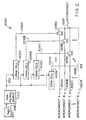
- FIG. 1 shows a portion of a PLD according to an embodiment 1000 of the invention.
- the PLD includes NMOS transistors 1008A, 1008B, and 1008C.
- Transistors 1008A-1008C constitute SOI NMOS transistors.
- the PLD also includes configuration random-access memory (CRAM) cells 1005A, 1005B, and 1005C, random-access memory (RAM) voltage source 1010, and a reference voltage source 1015.
- CRAM configuration random-access memory
- the CRAM cells 1005A-1005C may reside within a CRAM device or circuitry (not shown explicitly) and store configuration data for the PLD.
- the user may use the configuration data in the CRAM (for example, the data within the CRAM cells 1005A-1005C) to specify the programmable interconnects within the PLD, such as the interconnect shown in FIG. 1 .
- the user may program the CRAM cells 1005A-1005C by storing data bits within those cells.
- the PLD loads CRAM cells at device power-up by retrieving data from a data source.
- the data source provides user-specified data that determine the configuration and functionality of the PLD.
- the data source may constitute a variety of devices, such as a memory (e.g., a read-only memory (ROM), flash memory, erasable ROM, non-volatile memory, etc.), a source that supplies a bit-stream of data, a storage device, and the like, as desired.
- the CRAM cells 1005A-1005C provide control signals 1030A-1030C to NMOS SOI transistors 1008A-1008C.
- each of the control signals 1030A-1030C may turn on a respective one of NMOS SOI transistors 1008A-1008C.
- a logic high level on one of the control signals 1030A-1030C turns on the respective one of NMOS SOI transistors 1008A-1008C.
- one of the NMOS transistors 1008A-1008C turns on, it couples the corresponding one of interconnects 1020A-1020C to interconnect 1025.
- a logic low level on one of the control signals 1030A-1030C turns off the respective one of NMOS SOI transistors 1008A-1008C.
- the SOI transistor that is in the off state decouples the corresponding one of interconnects 1020A-1020C from interconnect 1025.
- the user can selectively couple each of interconnects 1020A-1020C to interconnect 1025, as desired, and thus realize a programmable interconnect within the PLD.
- Programming similar interconnects allows the user to specify and control the overall functionality that the PLD realizes.
- the programmable interconnect circuitry couples together various parts of the PLD, such as programmable logic circuitry, to provide the overall programmable functionality of the PLD as specified by the user.
- the reference voltage source 1015 supplies a voltage to RAM voltage source 1010 via an output 1040.
- RAM voltage source 1010 derives a voltage from the voltage at output 1040 of reference voltage source 1015 and supplies the derived voltage to CRAM cells 1005A-1005C via an output 1035.
- the CRAM cells 1005A-1005C may also set the voltage of the control signals 1030A-1030C to that level, thus avoiding a leakage path in pass transistors 1008A-1008C through forward-biased junctions.
- the PLD in embodiment 1000 can operate with lower supply voltages.
- programmable interconnects employing SOI transistors in the PLD in embodiment 1000 allow reliable transmission of logic 0 and logic 1 levels in the PLD even when operating from reduced power-supply voltages.
- FIG. 1 illustrates three CRAM cells 1005A-1005C, three SOI transistors 1008A-1008C, and three interconnects 1020A-1020C coupled to interconnect 1025.
- FIG. 1 illustrates three CRAM cells 1005A-1005C, three SOI transistors 1008A-1008C, and three interconnects 1020A-1020C coupled to interconnect 1025.
- FIG. 2 depicts such a generalized circuit arrangement.
- FIG. 2 shows a portion of a PLD according to an embodiment 2000 of the invention.
- Embodiment 2000 is similar to embodiment 1000, contains similar elements, and operates in a similar manner. Unlike embodiment 1000, however, embodiment 2000 includes K CRAM cells 1005A-1005K, K SOI transistors 1008A-1008K, and K interconnects 1020A-1020K. Similar to embodiment 1000, the PLD in embodiment 2000 includes (if the transistors used have their respective gates coupled to their respective bodies) random-access memory (RAM) voltage source 1010, and a reference voltage source 1015.
- RAM random-access memory
- CRAM cells 1005A-1005K provide control signals 1030A-1030K to SOI transistors 1008A-1008K. Depending on the data bits stored in CRAM cells 1005A-1005K, each of the control signals 1030A-1030K may turn on a respective one of SOI transistors 1008A-1008K.
- the user can selectively couple each of interconnects 1020A-1020K to interconnect 1025, and thus realize a programmable interconnect within the PLD with a particular functionality.
- embodiment 2000 realizes a programmable interconnect that can select its input signal from K input signals, based on the data bits stored in K CRAM cells. Note that, as discussed above, depending on the power-supply voltages used, one may omit RAM voltage source 1010 and reference voltage source 1015.
- programmable interconnects employing SOI transistors in the PLD in embodiment 2000 allow reliable operation of the PLD with reduced power-supply voltages. Put another way, the transistors in the PLD in embodiment 2000 transmit logic 0 and 1 levels reliably even when operating from relatively low power-supply voltages.
- embodiment 1000 and embodiment 2000 in FIGS. 1 and 2 show a single programmable interconnect 1025.
- One may, however, replicate embodiment 1000 and, more generally, embodiment 2000, to realize a desired number of programmable interconnects, as desired.
- by using replica of the circuitry in embodiment 1000 and/or embodiment 2000 one may implement desired numbers and/or configurations of interconnects within a PLD, as desired.
- the appropriate number, configuration, and/or functionality of the programmable interconnects depends on the design and performance specifications for a given application, as persons of ordinary skill in the art who have the benefit of the description of the invention understand.
- MOS transistors in PLDs according to the invention wherever a conventional PLD would use a pass transistor or device.
- Examples of applications include multiplexers, such as series coupled or cascaded multiplexers, and selective coupling between any two points or nodes within the PLD.
- the pass devices may couple to the programmable interconnect and to other parts of the PLD, for example programmable logic circuitry, which may include look-up table circuits, logic gates, and the like, as persons of ordinary skill in the art who have the benefit of the description of the invention understand.
- the pass devices may provide part of the programmable fabric of the PLD, as desired.
- FIG. 3 shows an embodiment 3000 of a portion of a PLD according to the invention that uses series SOI pass transistors.
- Embodiment 3000 includes SOI transistors 1008A and 1008B, and CRAM cells 1005A and 1005B.
- the SOI transistors 1008A-1008B and CRAM cells 1005A-1005B operate in a similar manner as those in embodiments 1000 and 2000 described above.
- SOI transistor 1008A receives an input signal from the output of CRAM cell 1005A. Depending on the value of the output of CRAM cell 1005A, SOI transistor 1008A selectively passes the input signal to SOI transistor 1008B. More specifically, if the output of CRAM cell 1005A has a logic 0 value, SOI transistor 1008A is in the off state and does not conduct current (except for sub-threshold leakage current and the like). Thus, SOI transistor 1008A decouples the input signal from SOI transistor 1008B ( i.e. , SOI transistor 1008A provides a relatively high impedance between its drain and source).
- SOI transistor 1008A turns on and provides a relatively low impedance to current flow.
- SOI transistor 1008A couples the input signal to intermediate node 3005 (effectively to SOI transistor 1008B).
- the signal at intermediate node 3005 is the same as the input signal (except for any losses or distortions that non-ideal characteristics of SOI transistor 1008A may cause).
- CRAM cell 1005B and SOI transistor 1008B operate in a similar manner.
- SOI transistor 1008B if the output of CRAM cell 1005B has a logic 0 value, SOI transistor 1008B is in the off state and does not conduct current (except for sub-threshold leakage current and other non-ideal behavior). Accordingly, SOI transistor 1008B decouples intermediate node 3005 from the output node. If, however, if the output of CRAM cell 1005B has a logic 1 value, SOI transistor 1008B turns on. Consequently, SOI transistor 1008B couples intermediate node 3005 to the output node. In other words, the output signal is substantially a replica of the signal at intermediate node 3005 (except for any losses or distortions because of non-ideal characteristics of SOI transistor 1008B).
- SOI transistor 1008A provides the input signal to intermediate node 3005, but SOI transistor 1008B decouples intermediate node 3005 from the output node.
- SOI transistor 1008A decouples the input from intermediate node 3005, while SOI transistor 1008B couples intermediate node 3005 to the output.
- SOI transistors 1008A and 1008B both turn on and couple the input to both the output and intermediate node 3005.
- Intermediate node 3005 may couple to various areas of the PLD, as desired.
- Embodiment 3000 may receive its input signal from within or outside the PLD and may provide its output signal to other parts of the PLD or as an output signal of the PLD.
- embodiment 3000 shows a cascade of two SOI transistors.
- One may, however, use a single SOI transistor as a pass transistor, as desired.
- one may use a cascade of more than one or two SOI transistors, as persons of ordinary skill in the art who have the benefit of the description of the invention understand.
- One may use any of the MOS transistors described below as transistors 1008A-1008B, as desired.
- one may insert other circuitry, such as buffers, inverters, gates, and the like between pass devices (between transistors 1008A-1008B), as desired.
- FIG. 4 shows another embodiment 4000 of a portion of a PLD according to the invention that uses series SOI pass transistors.
- Embodiment 4000 is a more general implementation of embodiment 3000. Thus, embodiment 4000 is similar to embodiment 3000, contains similar elements, and operates in a similar manner. Unlike embodiment 3000, however, embodiment 4000 includes M CRAM cells 1005A-1005M, M SOI transistors 1008A-1008M, and M intermediate nodes 3005A-3005M.
- CRAM cells 1005A-1005M provide output signals that control SOI transistors 1008A-1008M, respectively.
- SOI transistors 1008A-1008M may turn on.
- the user can selectively couple the circuit's input and the output to one or more intermediate nodes 3005A-3005M, and/or couple one or more intermediate nodes 3005A-3005M to one another.
- Intermediate nodes 3005 and/or 3005A-3005M may be available to, or drive, other nodes or circuitry within the PLD, as desired.
- embodiments 3000 and 4000 in FIGS. 3 and 4 respectively, show a single cascade of SOI transistors (or a single SOI pass transistor).
- One may, however, replicate embodiment 3000 and, more generally, embodiment 4000, to realize a desired number of cascaded SOI transistor (or single SOI pass transistors), as desired.
- the appropriate number, configuration, and/or functionality of the SOI pass transistors or cascades of SOI transistors depends on the design and performance specifications for a given application, as persons of ordinary skill in the art who have the benefit of the description of the invention understand.
- Embodiments 3000 and 4000 show control signals obtained from CRAM cells 1005A-1005B or 1005A-1005M.
- One may use other signals to control SOI transistors 1008A-1008B or 1008A-1008M, as desired.
- SOI transistors For example, one may use inputs to the PLD, signals at other points or from other circuitry in the PLD, logic signals derived by the circuitry within the PLD, etc. Regardless of the source of the signals that control the SOI transistors, using SOI transistors allows reliable transmission of logic 1 signals in PLDs that operate from relatively low supply voltages.
- one may insert other circuitry, such as buffers, inverters, gates, and the like between pass devices (between two of transistors 1008A-1008M), as desired.
- the look-up table circuits may couple to programmable interconnects, pass devices, and/or other parts of the PLD, for example programmable logic circuitry that may include logic gates and the like, as persons of ordinary skill in the art who have the benefit of the description of the invention understand.
- the look-up table circuits may provide part of the programmable fabric of the PLD, as desired.
- FIG. 5 shows an embodiment 5000 of a portion of a PLD according to the invention that incorporates SOI transistors in a look-up table circuit.
- Embodiment 5000 includes memory cells 5010A-5010D, SOI transistors 1008A-1008F, decoder 5005, and inverters 5015A-5015B.
- the combination of memory cells 5010A-5010D, SOI transistors 1008A-1008F, and inverters 5015A-5015B provides a look-up table circuit.
- Decoder 5005 may also constitute part of the look-up table circuit or, alternatively, may reside in another part or circuit within the PLD and supply input signals 5005A-5005B to the look-up table, as desired. As another alternative, another circuit (not shown explicitly) within or outside the PLD may supply input signals 5005A-5005B to the look-up table, as desired. Decoder 5005 (or other source of input signals) operates in a manner that persons skilled in the art with the benefit of the description of the invention understand. Note that, although the look-up circuit in FIG. 5 operates in response to two signals 5005A-5005B, one may generally provide look-up table circuits with other numbers of inputs signals ( e.g. , 4 or 6), as persons skilled in the art with the benefit of the description of the invention understand.
- the look-up table selectively supplies the contents of memory cells 5010A-5010D to output 5030.
- the look-up table does so depending on the logic values of input signals 5005A-5005B.
- the look-up table circuit supplies the output signal of one of memory cells 5010A-5010D to output 5030.
- By storing the truth table or a desired logic response in memory cells 5010A-5010D one may provide an output signal that corresponds to that truth table or logic response. Examples of logic responses include AND, NAND, OR, NOR, XOR, XNOR, adders, data converters, etc., as persons skilled in the art understand.
- one of SOI transistors 1008A-1008B turns on and, consequently, couples the output of a respective one of memory cells 5010A-5010B to intermediate node 5020.
- input signal 5005A has a logic low value
- SOI transistor 1008A is in the off state, thus decoupling the output of memory cell 5010A from intermediate node 5020.
- inverter 5015A provides a logic high value as its output signal 5015A1.
- SOI transistor 1008B turns on and couples the output of memory cell 5010B to intermediate node 5020.
- SOI transistor 1008A If input signal 5005A has a logic high value, however, SOI transistor 1008A is in the on state and couples the output of memory cell 5010A to intermediate node 5020. Because of the logic high value of input signal 5005A, inverter 5015A provides a logic low value as its output signal 5015A1. Consequently, SOI transistor 1008B turns off and decouples the output of memory cell 5010B from intermediate node 5020.
- SOI transistors 1008C and 1008D operate in a manner similar to SOI transistors 1008A and 1008B, respectively. More specifically, consider the situation where input signal 5005A has a logic low value. SOI transistor 1008C is in the off state and decouples the output of memory cell 5010C from intermediate node 5025. In response to the logic low value of input signal 5005A, inverter 5015A provides a logic high value as its output signal 5015A1. Accordingly, SOI transistor 1008D turns on and couples the output of memory cell 5010D to intermediate node 5025.
- SOI transistor 1008C turns on and couples the output of memory cell 5010C to intermediate node 5025.
- inverter 5015A provides a logic low value as its output signal 5015A1.
- SOI transistor 1008D therefore turns off and decouples the output of memory cell 5010D from intermediate node 5025.
- Input signal 5005B causes the transmission of one of the signals present at intermediate nodes 5020 and 5025 to output 5030.
- SOI transistors 1008E and 1008F provide one of the signals at intermediate nodes 5020 and 5025 as output signal 5030. If input signal 5005B has a logic low value, SOI transistor 1008E is in the off state, thus decoupling intermediate node 5020 from output 5030.
- inverter 5015B provides a logic high value as its output signal 5015B1. As a result, SOI transistor 1008F turns on and couples intermediate node 5025 to output 5030.
- SOI transistor 1008E is in the on state and couples intermediate node 5020 to output 5030. Because of the logic high value of input signal 5005B, inverter 5015B provides a logic low value as its output signal 5015B1. Consequently, SOI transistor 1008F turns off and decouples intermediate node 5025 from output 5030. Thus, overall, SOI transistors 1008A-1008F, under the control of input signals 5005A and 5005B, provide the output signal of one of memory cells 5010A-5010D as output signal 5030.
- embodiment 5000 shows a cascade of two SOI transistors in the look-up table circuit (for example, the cascade of SOI transistors 1008A and 1008E).
- One may, however, use a single SOI transistor as a pass transistor or device in PLDs according to the invention, as desired.
- FIG. 5 For example, one may modify FIG. 5 to provide a two-memory-cell look-up table circuit according to the invention that uses a single SOI pass transistor in the data path for each memory cell. To do so, one may omit SOI transistors 1008A-1008D, memory cells 5010B-5010C, and inverter 5015A from embodiment 5000. One may further couple the output of memory cell 5010A to SOI transistor 1008E, and couple the output of memory cell 5010D to SOI transistor 1008F. The resulting look-up table circuit includes memory cells 5010A and 5010D, SOI transistors 1008E and 1008F, and inverter 5015B. Depending on the logic value of input signal 5005B, SOI transistors 1008E-1008F couple the output of one of memory cells 5010A and 5010D to output 5030, in the similar manner to that described above.
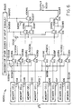
- FIG. 6 shows another embodiment 6000 of a portion of a PLD according to the invention that uses cascaded SOI pass transistors or devices.
- Embodiment 6000 is similar to embodiment 5000, contains similar elements, and operates in a similar manner. Unlike embodiment 5000, however, embodiment 6000 includes N input signals (labeled 5005A-5005E) and 2 N memory cells (labeled 5010A-5010H), where N constitutes an integer number greater than 2. Embodiment 6000 also includes inverters (labeled as 5015A-5015D), SOI transistors (labeled as 1008A-1008T), input signals 5005A-5005E, intermediate nodes (labeled as 5020A-5020F), and decoder 5005 (or other source of input signals, as described above).
- inverters labeleled as 5015A-5015D
- SOI transistors labeleled as 1008A-1008T
- input signals 5005A-5005E intermediate nodes
- intermediate nodes labeleled as 5020A-5020F
- decoder 5005 or other source of input signals, as described above.
- the number of memory cells 5010A-5010H, inverters 5015A-5015D, SOI transistors 1008A-1008T, input signals 5005A-5005E, and intermediate nodes 5020A-5020F depends on the value of the integer N, as persons skilled in the art with the benefit of the description of the invention understand.
- embodiment 6000 Similar to embodiment 5000, in embodiment 6000, input signals 5005A-5005E (together with the output signals of inverters 5015A-5015D), control SOI transistors 1008A-1008T.
- the operation of embodiment 6000 is similar to the operation of embodiment 5000, described above.
- embodiment 6000 includes repeated combinations of circuit elements, for example the combination that includes memory inverter 5015A and SOI transistors 1008A-1008D.
- the combination of circuit elements that includes inverter 5015A and SOI transistors 1008A-1008D operates in a similar manner to the combination of circuit elements in FIG. 5 that includes inverter 5015A and SOI transistors 1008A-1008D.
- the combination of circuit elements that includes inverter 5015B and SOI transistors 1008E-1008H operates in a similar manner to the similar combination of circuit elements in FIG. 5 ( i.e. , the combination of inverter 5015A and SOI transistors 1008A-1008D).
- embodiment 6000 provides the output of one of memory cells 5010A-5010H to output 5030, by steering the signal through selected intermediate nodes 5020A-5020E.
- look-up table circuits described above to realize a desired number and/or configuration of look-up tables with a desired functionality.
- the appropriate number, configuration, and/or functionality of the look-up table circuits depends on the design and performance specifications for a given application, as persons of ordinary skill in the art who have the benefit of the description of the invention understand.
- look-up table circuits according to the invention described here can operate from relatively small power-supply voltages.
- SOI pass transistors By using SOI pass transistors, look-up table circuits according to the invention can reliably transmit both logic 0 and logic 1 levels even with relatively small power-supply voltages. Note that one may use any of the MOS transistors or structures described below as transistors 1008A-1008F in embodiment 5000 or transistors 1008A-1008T in embodiment 6000, as desired.
- logic gates or logic circuitry including logic gates in PLDs according to the invention.
- the logic gates or logic circuitry may couple to programmable interconnects, pass devices, look-up table circuits, and/or other parts of the PLD, as persons of ordinary skill in the art who have the benefit of the description of the invention understand.
- the logic gates or logic circuitry may provide part of the programmable fabric of the PLD, as desired.
- FIG. 7 shows an embodiment 7000 of a logic gate incorporating SOI transistors for use in a PLD according to the invention.
- Embodiment 7000 illustrates a two-input NAND gate that includes PMOS transistors 7005A-7005B and SOI NMOS transistors 1008A-1008B. Persons of ordinary skill in the art who have the benefit of the description of the invention understand the operation of embodiment 7000.
- a NAND gate in a conventional PLD that uses ordinary NMOS transistors may suffer from degraded performance (e.g., longer switching times).
- the NAND gate in embodiment 7000 uses SOI NMOS transistors (although, note that one may implement the PMOS transistors using SOI technology, as desired).
- the NAND gate when used in PLDs according to the invention provides improved performance ( e.g., faster switching times).
- FIG. 8 shows another embodiment 8000 of a NAND gate with SOI transistors for use in a PLD according to the invention.
- Embodiment 8000 illustrates a NAND gate with M inputs, where M denotes an integer number greater than 2, and includes PMOS transistors 7005A-7005M and SOI NMOS transistors 1008A-1008M.
- Embodiment 8000 operates in a similar manner to embodiment 7000, as persons skilled in the art understand.
- the problem of degraded performance is even more acute in NAND gates with relatively large numbers of inputs.
- the NAND gate in embodiment 8000 uses SOI NMOS transistors.
- the NAND gate provides improved performance, such as shorter switching time.
- FIGS. 7-8 illustrate NAND gates
- SOI transistors in AND gates, NOR gates, and OR gates, as persons skilled in the art with the benefit of the description of the invention understand.
- CMOS technology rather than using CMOS technology, one may realize logic gates with SOI transistors in NMOS technology or PMOS technology, as desired, by making appropriate modifications that fall within the knowledge of persons of ordinary skill in the art who have the benefit of the description of the invention.
- NAND gates with SOI transistors in a variety of circuitry within PLDs according to the invention.
- Some examples include look-up table circuits, buffers, control logic, input/output (IO) circuitry, error detection and correction circuitry, and the like.
- MOS transistors in PLDs according to the invention, as described below. More specifically, one may use one or more of the MOS transistors described here in embodiments 1000-8000 shown in FIGS. 1-8 and described above.
- the gate of the transistor couples to its body region. Doing so creates a dynamic-threshold MOS (DTMOS) transistor.
- DTMOS transistors can reliably transmit both logic 0 and logic 1 levels, even when used in circuits in PLDs that operate from relatively low power-supply voltages.
- conventional MOS transistors i.e ., without the body region coupled to the gate terminal
- V T The threshold voltage, V T , depends on a number of factors, such as the voltage between the body region and the source region of the transistor.
- Equation 2B shows, for a finite body factor, ⁇ , the transistor's threshold voltage increases as the source-to-body voltage, ⁇ SB , increases. Equation 1, however, indicates that an increase in the threshold voltage decreases the drain current, i D , of the transistor. In other words, according to Equations 1 and 2B, for a constant gate-to-source-voltage, ⁇ GS , an increase in the source-to-body voltage, ⁇ SB , causes an increase in the threshold voltage, V T .
- An increased threshold voltage, V T causes a decrease in the quantity ( ⁇ QS -V T ) and, consequently, a decrease in the drain current, i D , of the transistor.
- ⁇ GS an increase in the source-to-body voltage, ⁇ SB , causes a decrease in the current-drive capability of the transistor.
- the decreased current-drive capability of the transistor in turn leads to slower circuit operation and, ultimately, to slower operation of the PLD that includes the transistor.
- an increase in the threshold voltage, V T limits the maximum voltage that the transistor can transmit when operating as a pass transistor.
- the threshold voltage, V T increases to the point that it equals or exceeds the gate-to-source-voltage, ⁇ GS , the drain current reduces to zero.
- a voltage applied to the drain of the transistor for example, a voltage that corresponds to a logic 1 level, fails to properly transmit to the source of the transistor. Consequently, the transistor fails to operate reliably as a pass transistor.
- an increase in the gate-to-source voltage, ⁇ GS results in a direct increase in the body-to-source voltage, ⁇ BS .
- an increase in the body-to-source voltage, ⁇ BS decreases the quantity 2 ⁇ ⁇ F - v BS - 2 ⁇ ⁇ F , which results in a decrease in the threshold voltage, V T .
- DTMOS transistor a MOS transistor in which one may dynamically change the threshold voltage by varying the gate voltage
- a decrease in the threshold voltage, V T allows the DTMOS transistor to have the capability of transmitting higher voltage levels, for example, a logic 1 voltage level.
- DTMOS transistors can reliably transmit logic 1 voltage levels in PLDs with relatively low supply voltages.
- a decrease in the threshold voltage, V T results in increased current-drive capability and, hence, faster circuit operation.
- PLDs according to the invention that contain DTMOS transistors can operate at faster speeds because of the increased current drive capability of the transistors.
- FIG. 9 illustrates an embodiment 10000 of a DTMOS SOI transistor, with its gate coupled to its body region, for use in PLDs according to the invention.
- One may use the transistor in embodiment 10000 in any of the circuitry described above for inclusion in a PLD.
- the transistor in embodiment 10000 has drain region 9005, source region 9010, gate 9015, and body region 9025.
- a insulator layer 9020 (gate insulator) resides above channel region 9030 of the transistor.
- Gate 9015 resides above insulator layer 9020.
- insulator layer 9020 constitutes silicon dioxide (SiO 2 ), although one may use other suitable insulators, as persons of ordinary skill in the art understand.
- insulator layer 10005 may constitute silicon dioxide, although one may use other types of insulator, as persons of ordinary skill in the art understand.
- Insulator layer 10005 resides above substrate region 10010.
- substrate region 10010 may constitute the substrate of the PLD die within which embodiment 10000 resides.
- insulator layer 10005 By using insulator layer 10005, one may provide an insulated well or region for each implementation of embodiment 10000 in a PLD according to the invention. Using insulator layer 10005 may also decrease parasitic capacitance values of the transistor and, thus, of the PLD. The decrease in parasitic capacitance values increases the operating speed of the transistor in embodiment 10000 and, consequently, of the PLD that contains it.
- FIG. 10 shows an embodiment 11000 of another SOI transistor for use in PLDs according to the invention.
- One may use the transistor in embodiment 11000 in any of the circuitry described above (see FIGS. 1-8 ). Note that, unlike embodiment 10000, in embodiment 11000, body 9025 does not couple to gate 9015. Because body 9025 does not couple to gate 9015, the transistor in embodiment 11000 constitutes a floating-body transistor.
- the transistor in embodiment 11000 has a similar structure to the transistor in embodiment 10000 (see FIG. 9 ).
- the transistor in embodiment 11000 includes drain region 9005, source region 9010, gate 9015, and body region 9025.
- Insulator layer 9020 (gate insulator) resides above channel region 9030 of the transistor.
- Gate 9015 resides above insulator layer 9020.
- insulator layer 9020 constitutes silicon dioxide (SiO 2 ), although one may use other suitable insulators, as persons skilled in the art understand.
- insulator layer 10005 may constitute silicon dioxide, although one may use other types of insulator, as persons of ordinary skill in the art understand.
- substrate region 10010 may constitute the substrate of the PLD within which embodiment 11000 resides.
- insulator layer 10005 By using insulator layer 10005, one may provide an insulated well or region for each implementation of embodiment 11000 in a PLD according to the invention. Use of insulator layer 10005 may also decrease parasitic capacitance values of the transistor and, hence, of the PLD in which the transistor resides. The decrease in parasitic capacitance values increases the operating speed of the transistor in embodiment 11000. As a result, the operating speed of the PLD that includes embodiment 11000 increases.
- FDMOS fully depleted MOS
- PDMOS partially depleted MOS
- the terms fully depleted and partially depleted refer to a depletion layer (not shown explicitly) in body region 9025 of the transistor.
- the depletion layer results from an application of a gate potential to gate 9015 of the transistor.
- the width of the depletion layer spans body region 9025.
- the width of the depletion layer does not span the entire body region 9025.
- DTMOS transistors differ from the FDMOS or PDMOS transistors in several respects.
- the DTMOS transistors have their gates coupled to their respective bodies.
- the FDMOS or PDMOS transistors do not use that coupling, thus allowing savings in PLD area and/or the material used (e.g. , metal, silicon dioxide, vias, and/or polysilicon) to provide the couplings.
- the material used e.g. , metal, silicon dioxide, vias, and/or polysilicon
- implementing and routing PLD interconnects or signal lines to other circuitry in the PLD that includes those transistors may be relatively easy.
- FDMOS and PDMOS transistors exhibit a so-called “history effect.”
- the history effect arises because of the finite time it takes for induced charges in body region 9025 to settle once the switching stops.
- the history effect may lower the effective operating speeds of FDMOS and PDMOS transistors. Consequently, DTMOS transistors may have higher relative operating speeds compared to FDMOS and PDMOS transistors.
- DTMOS, FDMOS, or PDMOS transistors based on the above factors, as well as factors relating to the design and performance specifications for a given application, as persons skilled in the art with the benefit of the description of the invention understand.
- FIG. 11 shows an embodiment 14000 of an SOI double-gate MOS transistor for use in PLDs according to the invention.
- the transistor in embodiment 14000 includes drain region 9005, source region 9010, and body region 9025.
- the transistor in embodiment 14000 has an upper gate 9015A and a lower gate 9015B.
- An insulator layer 9020A (upper-gate insulator) resides above upper channel region 9030A of the transistor.
- Upper gate 9015A resides above insulator layer 9020A.
- Another insulator layer 9020B1 (lower-gate insulator) resides below lower channel region 9030B of the transistor.
- Lower gate 9015B resides below insulator layer 9020B1.
- Insulator layer 9020B2 resides below lower gate 9015B.
- Substrate 10010 generally resides below insulator layer 9020B2.
- insulator layers 9020A, 9020B1, and 9020B2 constitute silicon dioxide (SiO 2 ), although one may use other suitable insulators, as desired.
- substrate region 10010 may constitute the substrate of the PLD within which embodiment 14000 resides.
- insulator layer 9020B2 By using insulator layer 9020B2, one may provide an insulated well or body region for each implementation of embodiment 14000 in a PLD according to the invention. Use of insulator layer 9020B2 may also decrease parasitic capacitance values of the transistor and, thus, of the PLD. The decrease in parasitic capacitance values increases the operating speed and lowers the switching power dissipation of the transistor in embodiment 14000 and, consequently, of the PLD.
- FDMOS fully depleted MOS
- PDMOS partially depleted MOS
- the characteristics of the transistor such as various doping concentrations, for example, the doping concentrations of body region 9025 and/or channel regions 9030A-9030B, and/or the thickness of insulator layers 9020A and 9020B1
- PDMOS a PDMOS or an FDMOS transistor, as desired.
- the FDMOS and PDMOS configurations have properties similar to those described above in detail.
- embodiment 14000 may implement embodiment 14000 as a DTMOS transistor, as desired.
- a DTMOS transistor To configure the transistor as a DTMOS transistor, one may couple upper gate 9015A to lower gate 9015B and to body 9025.
- transistors as shown in embodiment 14000 reliably transmit logic 0 and logic 1 levels in PLDs according to the invention.
- FIGS. 12-15 show illustrative embodiments of data-processing systems that include PLDs according to the invention.
- the PLDs shown in FIG. 12-15 may include one or more of the circuitry and/or transistors described above.
- the various parts of the PLDs, such as programmable interconnects, pass devices or transistors, look-up table circuits, and/or logic gates or logic circuitry may couple together (not shown explicitly in FIGS. 12-15 ), as described above, and as persons of ordinary skill in the art who have the benefit of the description of the invention understand.
- FIG. 12 shows an embodiment 15000 of a data-processing system that includes a PLD 15005 according to the invention.
- Embodiment 15000 also includes one or more peripherals 15010.
- Peripheral(s) 15010 couple to PLD 15005 via signal links 15015.
- Signal links 15015 may constitute any suitable signal lines or a collection of a plurality of signal lines ( i.e ., a plurality of signal lines coupled to each of peripherals 15010, and the collection of the plurality of signal lines constituting signal links 15015).
- PLD 15005 may include one or more of the following circuits, described above: (a) programmable interconnect according to embodiments 1000 and/or 2000; (b) series pass device according to embodiments 3000 and/or 4000; (c) look-up table circuit according to embodiments 5000 and/or 6000; and (d) multi-input logic circuits or gates according to embodiments 7000 and/or 8000.
- the circuitry within PLD 15005, for example, the programmable interconnect or the look-up table circuit or the other circuitry described above, may include MOS transistors according to the embodiments described above.
- Peripherals 15010 may include a variety of devices or circuits, as persons skilled in the art with the benefit of the disclosure of the invention recognize.
- peripherals 15010 may include communication or telecommunication circuitry, video circuitry, audio circuitry, input circuitry, output circuitry, storage circuitry, memory circuitry, and network circuitry, as desired.
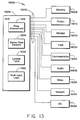
- FIG. 13 shows another embodiment 16000 of a data-processing system that includes PLD 15005 according to the invention.
- Embodiment 16000 includes a plurality of peripherals 16005-16045 that couple to PLD 15005 via a plurality of signal links 15015.
- Signal links 15015 may constitute any suitable signal lines or a collection of a plurality of signal lines ( i.e ., a plurality of signal lines coupled to each of peripherals 16005-16045, and the collection of the plurality of signal lines constituting signal links 15015).
- PLD 15005 may include one or more of the following circuitry: (a) programmable interconnect according to embodiments 1000 and/or 2000; (b) series pass device according to embodiments 3000 and/or 4000; (c) look-up table circuit according to embodiments 5000 and/or 6000; and (d) multi-input logic circuits or gates according to embodiments 7000 and/or 8000.
- the circuitry within PLD 15005, for example, the programmable interconnect or the look-up table circuit or any of the other circuitry described above, may include MOS transistors according to the embodiments described above.
- Peripherals 16005-16045 include one or more memory 16005 (e.g., SDRAM circuitry and associated controller), output circuitry 16010 (e.g., a printer), storage circuitry 16015 ( e.g. , a hard drive), input circuitry 16020 ( e.g., a keyboard), communication circuitry 16025 ( e.g., a modem), audio circuitry 16030 ( e.g., sound card, speakers), video circuitry 16035 ( e.g., a video controller, monitor, or both), network circuitry 16040 (e.g., an Ethernet controller or network interface card), and I/O circuitry 16045 (e.g., game controller or joystick).
- memory 16005 e.g., SDRAM circuitry and associated controller
- output circuitry 16010 e.g., a printer
- storage circuitry 16015 e.g. , a hard drive
- input circuitry 16020 e.g., a keyboard
- communication circuitry 16025 e.g.
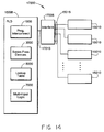
- FIG. 14 shows an alternative embodiment 17000 of a data-processing system that includes PLD 15005 according to the invention.
- PLD 15005 may include one or more of the following circuitry: (a) programmable interconnect according to embodiments 1000 and/or 2000; (b) series pass device according to embodiments 3000 and/or 4000; (c) look-up table circuit according to embodiments 5000 and/or 6000; and (d) multi-input logic circuits or gates according to embodiments 7000 and/or 8000.
- the circuitry within PLD 15005, for example, the programmable interconnect or the look-up table circuit or other circuitry described above, may include MOS transistors according to the embodiments described above.
- Embodiment 17000 also includes one or more peripherals 15010.
- Peripheral(s) 15010 couple to PLD 15005 via interface circuit 17005.
- Peripherals 15010 may include a variety of devices or circuits, as persons skilled in the art recognize.
- peripherals 15010 may include communication or telecommunication circuitry, video circuitry, audio circuitry, input circuitry, output circuitry, storage circuitry, memory circuitry, and network circuitry, as desired.
- Signal links 15015 may constitute any suitable signal lines or a collection of a plurality of signal lines (i.e. , a plurality of signal lines coupled to each of peripherals 15010, and the collection of the plurality of signal lines constituting signal links 15015).
- Interface circuit 17005 couples to PLD 15005 via a signal link 17010.
- Signal link 17010 may constitute any suitable line or link, for example, a bus or multiple buses (such as address and data buses), as desired.
- signal link 17010 may include one or more separate or specialized status, data, and/or control signals, as desired.
- the interface circuit 17005 uses signal links 15015 and 17010 to communicate data signals, status signals, and/or control signals between PLD 15005 and peripherals 15010. Interface circuit 17005 may also control the operation of peripherals 15010, either individually, or with the supervision of PLD 15005, as desired.
- FIG. 15 illustrates another alternative embodiment 18000 of a data-processing system that includes PLD 15005 according to the invention.
- PLD 15005 may include one or more of the following circuitry: (a) programmable interconnect according to embodiments 1000 and/or 2000; (b) series pass device according to embodiments 3000 and/or 4000; (c) look-up table circuit according to embodiments 5000 and/or 6000; and (d) multi-input logic circuits or gates according to embodiments 7000 and/or 8000.
- the circuitry within PLD 15005, for example, the programmable interconnect or the look-up table circuit or other circuitry described above, may include MOS transistors according to the embodiments described above.
- Embodiment 18000 includes a plurality of peripherals 16005-16045.
- Peripherals 16005-16045 include one or more memory 16005 (e.g., SDPAM circuitry and associated controller), output circuitry 16010 (e.g., a printer), storage circuitry 16015 ( e.g., a hard drive), input circuitry 16020 ( e.g., a keyboard), communication circuitry 16025 ( e.g., a modem), audio circuitry 16030 ( e.g., sound card, speakers), video circuitry 16035 ( e.g., a video controller, monitor, or both), network circuitry 16040 (e.g., an Ethernet controller or network interface card), and I/O circuitry 16045 (e.g., game controller or joystick).
- memory 16005 e.g., SDPAM circuitry and associated controller
- output circuitry 16010 e.g., a printer
- storage circuitry 16015 e.g., a hard drive
- peripherals 16005-16045 in embodiment 18000 couple to interface circuit 17005 via signal links 15015.
- Signal links 15015 may constitute any suitable signal lines or a collection of a plurality of signal lines ( i.e. , a plurality of signal lines coupled to each of peripherals 16005-16045, and the collection of the plurality of signal lines constituting signal links 15015).
- Interface circuit 17005 couples to PLD 15005 via a signal link 17010.
- Signal link 17010 may constitute any suitable line or link, for example, a bus or multiple buses (such as address and data buses), as desired.
- signal link 17010 may include one or more separate or specialized status, data, and/or control signals, as desired.
- interface circuit 17005 uses signal links 15015 and 17010 to communicate data signals, status signals, and/or control signals between PLD 15005 and peripherals 16005-16045. Interface circuit 17005 may also control the operation of peripherals 16005-16045, either individually, or with the supervision of PLD 15005, as desired.
- PLD 15005 may also include one or more processors, as desired.
- the processor or processors may couple (not shown explicitly) to various parts of the PLD (such as the programmable interconnect, pass devices or transistors, look-up table circuits, and/or logic gates or logic circuitry) and/or peripherals 15010.
- the processor or processors may operate on the data within the data-processing systems and decode and execute instructions.
- the processor or processors may couple to and/or communicate with peripherals 15010, as desired.
- peripherals 15010 may couple to and/or communicate with a given processor, as desired.
- more than one processor may couple to and/or communicate with a given one of peripherals 15010, as desired.
- PLD 15005 may also include one or more processors, as desired.
- the processor or processors may couple (not shown explicitly) to various parts of the PLD (such as the programmable interconnect, pass devices or transistors, look-up table circuits, and/or logic gates or logic circuitry) and/or peripherals 16005-16045.
- the processor or processors may operate on the data within the data-processing systems and decode and execute instructions.
- the processor or processors may couple to and/or communicate with peripherals 16005-16045, as desired.
- more than one of peripherals 16005-16045 may couple to and/or communicate with a given processor, as desired.
- more than one processor may couple to and/or communicate with a given one of peripherals 16005-16045, as desired.
- FIGS. 12-15 show PLD 15005 as including programmable interconnect, series pass devices, look-up table circuit, and multi-input logic circuit or gate, note that one may use each of such circuits and devices alone in a given data-processing system, as desired. For example, one may use a data-processing system that includes a PLD that includes only programmable interconnects according to the invention. As another example, one may have a data-processing system that uses a PLD with only look-up table circuits according to the invention. Furthermore, one may combine one or more such devices in a PLD according to the invention. In addition to the data-processing systems shown in FIGS. 12-15 , one may use other data-processing systems that use PLDs according to the invention, as persons of ordinary skill in the art who have the benefit of the description of the invention understand.
- MOS structures and transistors described above may be any of the varieties of MOS structures and transistors described above in PLDs according to the invention. More specifically, one may use any of the different kinds of MOS structures and transistors in programmable interconnect, series pass devices, look-up table circuits, and multi-input logic circuits or gates within PLDs according to the invention. Each of those MOS structures and transistors described above provide reliable transmission of logic 0 and logic 1 levels in PLDs according to the invention. In addition, using the SOI transistors in PLDs according to the invention may provide other benefits, such as decreased parasitic capacitance, increased operating speeds, and/or decreased switching power dissipation.
- N-type MOS NMOS
- CMOS complementary metal-oxide-semiconductor
- P-type MOS transistors P-type MOS transistors
- the exemplary embodiments of the invention described here pertain to using a variety of disclosed transistors in programmable interconnect, pass devices or transistors, look-up table circuits, and/or multi-input logic circuits or gates in PLDs. Note, however, that one may generally use the disclosed transistors in other areas of PLDs, as persons of ordinary skill in the art who have the benefit of the description of the invention understand. Furthermore, in addition to the transistors labeled as "SOI" in the accompanying figures, one may implement other transistors in the illustrated circuitry as SOI transistors. As persons of ordinary skill in the art with the benefit of the description of the invention understand, one may implement each SOI transistor using any of the varieties of transistors described here.
- the various blocks shown depict mainly the conceptual functions and signal flow.
- the actual circuit implementation may or may not contain separately identifiable hardware for the various functional blocks.
- the choice of circuit implementation depends on various factors, such as particular design and performance specifications for a given implementation, as persons of ordinary skill in the art who have read the disclosure of the invention will understand.
Claims (16)
- Réseau logique programmable (PLD - Programmable Logic Device) qui comprend des transistors à silicium sur isolant (SOI - Silicon-On-Insulator) (1008A à 1008M), le réseau logique programmable comprenant :un ensemble de circuits d'interconnexion programmables (1000, 2000) comprenant un premier transistor à silicium sur isolant, l'ensemble de circuits d'interconnexion programmables étant conçus pour permettre des interconnexions configurables au sein du réseau logique programmable ;un transistor de chute à silicium sur isolant, le transistor de chute à silicium sur isolant étant couplé à l'ensemble de circuits d'interconnexion programmables ; etun circuit de table de recherche (5000, 6000) comprenant un deuxième transistor à silicium sur isolant, le circuit de table de recherche étant couplé à l'ensemble de circuits d'interconnexion programmables.
- Réseau logique programmable (PLD) selon la revendication 1, dans lequel les premiers transistors à silicium sur isolant comprennent : (a) un transistor à semi-conducteur à oxyde métallique à tension de seuil dynamique (DTMOS), (b) un transistor à semi-conducteur à oxyde métallique complètement appauvri (FDMOS), (c) un transistor à semi-conducteur à oxyde métallique partiellement appauvri (PDMOS) ou (d) un transistor à semi-conducteur à oxyde métallique à double porte.
- Réseau logique programmable (PLD) selon la revendication 2, dans lequel le transistor de chute à silicium sur isolant comprend : a) un transistor à semi-conducteur à oxyde métallique à tension de seuil dynamique (DTMOS), (b) un transistor à semi-conducteur à oxyde métallique complètement appauvri (FDMOS), (c) un transistor à semi-conducteur à oxyde métallique partiellement appauvri (PDMOS) ou (d) un transistor à semi-conducteur à oxyde métallique à double porte.
- Réseau logique programmable (PLD) selon la revendication 3, dans lequel le deuxième transistor 0 silicium sur isolant comprend : a) un transistor à semi-conducteur à oxyde métallique à tension de seuil dynamique (DTMOS), (b) un transistor à semi-conducteur à oxyde métallique complètement appauvri (FDMOS), (c) un transistor à semi-conducteur à oxyde métallique partiellement appauvri (PDMOS) ou (d) un transistor à semi-conducteur à oxyde métallique à double porte.
- Réseau logique programmable (PLD) selon la revendication 4, comprenant en outre un circuit logique à entrées multiples (7000, 8000) couplé à l'ensemble de circuits d'interconnexion programmables, le circuit logique à entrées multiples comprenant un troisième transistor à silicium sur isolant.
- Réseau logique programmable (PLD) selon la revendication 5, dans lequel le troisième transistor à silicium sur isolant comprend : a) un transistor à semi-conducteur à oxyde métallique à tension de seuil dynamique (DTMOS), (b) un transistor à semi-conducteur à oxyde métallique complètement appauvri (FDMOS), (c) un transistor à semi-conducteur à oxyde métallique partiellement appauvri (PDMOS) ou (d) un transistor à semi-conducteur à oxyde métallique à double porte.
- Réseau logique programmable (PLD) selon la revendication 6, le réseau logique programmable comprenant un ensemble de circuits à semi-conducteur à oxyde métallique complémentaire (CMOS).
- Réseau logique programmable (PLD) selon la revendication 7, dans lequel le circuit logique à entrées multiples comprend au moins une porte NON-ET à entrées multiples ou au moins une porte NON-OU à entrées multiples, ou une combinaison de celles-ci.
- Réseau logique programmable (PLD) selon la revendication 7, dans lequel le circuit logique à entrées multiples comprend au moins une porte ET à entrées multiples ou au moins une porte OU à entrée multiple, ou une combinaison de celles-ci.
- Système de traitement de données, comprenant :un réseau logique programmable selon l'une quelconque des revendications 1 à 9 et ;au moins un dispositif périphérique couplé au réseau logique programmable,dans lequel la pluralité de transistors à semi-conducteur à oxyde métallique comprennent au moins un transistor à silicium sur isolant (SOI).
- Procédé de traitement de données utilisant un réseau logique programmable (PLD), comprenant :la réception de données d'entrée dans un ensemble de circuits électroniques programmables inclus dans le réseau logique programmable ; etle traitement des données d'entrée dans l'ensemble de circuits électroniques programmables du réseau logique programmable,dans lequel l'ensemble de circuits électroniques programmables comprend au moins un transistor SOI ;le procédé étant caractérisé en ce que la réception et le traitement des données d'entrée dans l'ensemble de circuits électroniques programmables comprennent en outre l'utilisation d'au moins une interconnexion programmable incluse à l'intérieur de l'ensemble de circuits électroniques programmables,dans lequel l'au moins une interconnexion programmable comprend : (a) au moins un transistor à semi-conducteur à oxyde métallique à tension de seuil dynamique (DTMOS), (b) au moins un transistor à semi-conducteur à oxyde métallique complètement appauvri (FDMOS), (c) au moins un transistor à semi-conducteur à oxyde métallique partiellement appauvri (PDMOS) ou (d) au moins un transistor à semi-conducteur à oxyde métallique à double porte, ou une combinaison de ceux-ci,dans lequel la réception et le traitement des données d'entrée dans l'ensemble de circuits électroniques programmables comprennent en outre l'utilisation d'au moins un transistor de chute couplé à l'au moins une interconnexion programmable,dans lequel l'au moins un dispositif de chute comprend : (a) un transistor à semi-conducteur à oxyde métallique à tension de seuil dynamique (DTMOS), (b) un transistor à semi-conducteur à oxyde métallique complètement appauvri (FDMOS), (c) un transistor à semi-conducteur à oxyde métallique partiellement appauvri (PDMOS), ou (d) un transistor à semi-conducteur à oxyde métallique à double porte, ou une combinaison de ceux-ci,dans lequel la réception et le traitement des données d'entrée dans l'ensemble de circuits électroniques programmables comprennent en outre l'utilisation d'au moins un circuit de table de recherche couplé à l'au moins une interconnexion programmable,dans lequel l'au moins un circuit de table de recherche comprend : a) au moins un transistor à semi-conducteur à oxyde métallique à tension de seuil dynamique (DTMOS), (b) au moins un transistor à semi-conducteur à oxyde métallique complètement appauvri (FDMOS), (c) au moins un transistor à semi-conducteur à oxyde métallique partiellement appauvri (PDMOS) ou (d) au moins un transistor à semi-conducteur à oxyde métallique à double porte, ou une combinaison de ceux-ci.
- Procédé selon la revendication 11, dans lequel la réception et le traitement des données d'entrée dans l'ensemble de circuits électroniques programmables comprennent en outre l'utilisation d'au moins un circuit logique à entrées multiples couplé à l'au moins une interconnexion programmable.
- Procédé selon la revendication 12, dans lequel l'au moins un circuit logique à entrées multiples comprend : a) au moins un transistor à semi-conducteur à oxyde métallique à tension de seuil dynamique (DTMOS), (b) au moins un transistor à semi-conducteur à oxyde métallique complètement appauvri (FDMOS), (c) au moins un transistor à semi-conducteur à oxyde métallique partiellement appauvri (PDMOS) ou (d) au moins un transistor à semi-conducteur à oxyde métallique à double porte, ou une combinaison de ceux-ci.
- Procédé selon la revendication 13, dans lequel le traitement des données à l'aide d'un réseau logique programmable comprend le traitement des données à l'aide d'un réseau logique programmable qui réside dans un système de traitement de données.
- Procédé selon la revendication 14, dans lequel le système de traitement de données comprend au moins un périphérique couplé au réseau logique programmable.
- Procédé selon la revendication 15, dans lequel le traitement des données à l'aide d'un réseau logique programmable comprend le traitement des données à l'aide d'un réseau logique programmable qui comprend un processeur couplé à l'interconnexion programmable.
Applications Claiming Priority (4)
| Application Number | Priority Date | Filing Date | Title |
|---|---|---|---|
| US32817101P | 2001-10-10 | 2001-10-10 | |
| US328171P | 2001-10-10 | ||
| US154394 | 2002-05-23 | ||
| US10/154,394 US6781409B2 (en) | 2001-10-10 | 2002-05-23 | Apparatus and methods for silicon-on-insulator transistors in programmable logic devices |
Publications (3)
| Publication Number | Publication Date |
|---|---|
| EP1304803A2 EP1304803A2 (fr) | 2003-04-23 |
| EP1304803A3 EP1304803A3 (fr) | 2007-01-17 |
| EP1304803B1 true EP1304803B1 (fr) | 2012-12-19 |
Family
ID=26851412
Family Applications (1)
| Application Number | Title | Priority Date | Filing Date |
|---|---|---|---|
| EP02022570A Expired - Fee Related EP1304803B1 (fr) | 2001-10-10 | 2002-10-08 | Circuit logique programmable comprenant des transistors à silicium sur isolant |
Country Status (4)
| Country | Link |
|---|---|
| US (2) | US6781409B2 (fr) |
| EP (1) | EP1304803B1 (fr) |
| JP (1) | JP2003179141A (fr) |
| CN (1) | CN1414705A (fr) |
Families Citing this family (29)
| Publication number | Priority date | Publication date | Assignee | Title |
|---|---|---|---|---|
| US6781409B2 (en) * | 2001-10-10 | 2004-08-24 | Altera Corporation | Apparatus and methods for silicon-on-insulator transistors in programmable logic devices |
| US6992503B2 (en) * | 2002-07-08 | 2006-01-31 | Viciciv Technology | Programmable devices with convertibility to customizable devices |
| US7112994B2 (en) | 2002-07-08 | 2006-09-26 | Viciciv Technology | Three dimensional integrated circuits |
| US7673273B2 (en) * | 2002-07-08 | 2010-03-02 | Tier Logic, Inc. | MPGA products based on a prototype FPGA |
| US8643162B2 (en) * | 2007-11-19 | 2014-02-04 | Raminda Udaya Madurawe | Pads and pin-outs in three dimensional integrated circuits |
| WO2005013490A1 (fr) * | 2003-08-05 | 2005-02-10 | Koninklijke Philips Electronics N.V. | Module de commutation pour circuit logique programmable par l'utilisateur |
| US7030651B2 (en) | 2003-12-04 | 2006-04-18 | Viciciv Technology | Programmable structured arrays |
| US7176713B2 (en) * | 2004-01-05 | 2007-02-13 | Viciciv Technology | Integrated circuits with RAM and ROM fabrication options |
| US7287171B1 (en) | 2004-03-08 | 2007-10-23 | Altera Corporation | Systems and methods for reducing static and total power consumption in programmable logic device architectures |
| US7348827B2 (en) * | 2004-05-19 | 2008-03-25 | Altera Corporation | Apparatus and methods for adjusting performance of programmable logic devices |
| US7129745B2 (en) * | 2004-05-19 | 2006-10-31 | Altera Corporation | Apparatus and methods for adjusting performance of integrated circuits |
| US7112997B1 (en) | 2004-05-19 | 2006-09-26 | Altera Corporation | Apparatus and methods for multi-gate silicon-on-insulator transistors |
| US7198993B2 (en) | 2004-12-13 | 2007-04-03 | Texas Instruments Incorporated | Method of fabricating a combined fully-depleted silicon-on-insulator (FD-SOI) and partially-depleted silicon-on-insulator (PD-SOI) devices |
| US7410840B2 (en) * | 2005-03-28 | 2008-08-12 | Texas Instruments Incorporated | Building fully-depleted and bulk transistors on same chip |
| US7410841B2 (en) * | 2005-03-28 | 2008-08-12 | Texas Instruments Incorporated | Building fully-depleted and partially-depleted transistors on same chip |
| US7486111B2 (en) * | 2006-03-08 | 2009-02-03 | Tier Logic, Inc. | Programmable logic devices comprising time multiplexed programmable interconnect |
| US7800403B2 (en) * | 2006-06-07 | 2010-09-21 | Bae Systems Information And Electronic Systems Integration Inc. | Universal non-volatile support device for supporting reconfigurable processing systems |
| US20080024165A1 (en) * | 2006-07-28 | 2008-01-31 | Raminda Udaya Madurawe | Configurable embedded multi-port memory |
| KR100887069B1 (ko) * | 2007-07-24 | 2009-03-04 | 주식회사 하이닉스반도체 | 상 변화 메모리 장치 |
| US7629812B2 (en) * | 2007-08-03 | 2009-12-08 | Dsm Solutions, Inc. | Switching circuits and methods for programmable logic devices |
| US7812408B1 (en) | 2007-10-16 | 2010-10-12 | Altera Corporation | Integrated circuits with metal-oxide-semiconductor transistors having enhanced gate depletion layers |
| US8230375B2 (en) | 2008-09-14 | 2012-07-24 | Raminda Udaya Madurawe | Automated metal pattern generation for integrated circuits |
| US9053272B2 (en) * | 2011-07-15 | 2015-06-09 | Tictran Corp. | Method and apparatus of hardware acceleration of EDA tools for a programmable logic device |
| US8633731B1 (en) * | 2011-08-09 | 2014-01-21 | Altera Corporation | Programmable integrated circuit with thin-oxide passgates |
| FR2987710B1 (fr) * | 2012-03-05 | 2017-04-28 | Soitec Silicon On Insulator | Architecture de table de correspondance |
| FR2987709B1 (fr) * | 2012-03-05 | 2017-04-28 | Soitec Silicon On Insulator | Table de correspondance |
| FR2987959B1 (fr) * | 2012-03-06 | 2014-03-14 | Soitec Silicon On Insulator | Multiplexeur, table de correspondance et fgpa |
| US8896344B1 (en) | 2013-01-04 | 2014-11-25 | Altera Corporation | Heterogeneous programmable device and configuration software adapted therefor |
| US10469076B2 (en) * | 2016-11-22 | 2019-11-05 | The Curators Of The University Of Missouri | Power gating circuit utilizing double-gate fully depleted silicon-on-insulator transistor |
Family Cites Families (18)
| Publication number | Priority date | Publication date | Assignee | Title |
|---|---|---|---|---|
| JPH0194722A (ja) | 1987-10-07 | 1989-04-13 | Sharp Corp | イオン注入によるプログラム可能論理素子 |
| US4972105A (en) | 1989-09-22 | 1990-11-20 | The U.S. Government As Represented By The Director, National Security Agency | Programmable configurable logic memory |
| US5309046A (en) * | 1992-09-30 | 1994-05-03 | Intel Corporation | Apparatus and method for product term allocation in programmable logic |
| US5525814A (en) * | 1995-01-19 | 1996-06-11 | Texas Instruments Incorporated | Three dimensional integrated latch and bulk pass transistor for high density field reconfigurable architecture |
| US5861650A (en) * | 1996-08-09 | 1999-01-19 | Mitsubishi Denki Kabushiki Kaisha | Semiconductor device comprising an FPGA |
| JP3195256B2 (ja) * | 1996-10-24 | 2001-08-06 | 株式会社東芝 | 半導体集積回路 |
| US5773331A (en) * | 1996-12-17 | 1998-06-30 | International Business Machines Corporation | Method for making single and double gate field effect transistors with sidewall source-drain contacts |
| US6405213B1 (en) * | 1997-05-27 | 2002-06-11 | Hoyt M. Layson | System to correlate crime incidents with a subject's location using crime incident data and a subject location recording device |
| US6239615B1 (en) * | 1998-01-21 | 2001-05-29 | Altera Corporation | High-performance interconnect |
| JP3684901B2 (ja) * | 1999-03-02 | 2005-08-17 | 富士ゼロックス株式会社 | 情報処理システム |
| US6365465B1 (en) * | 1999-03-19 | 2002-04-02 | International Business Machines Corporation | Self-aligned double-gate MOSFET by selective epitaxy and silicon wafer bonding techniques |
| JP2000323720A (ja) * | 1999-05-11 | 2000-11-24 | Yoshifumi Ando | シリコン・オン・インシュレータ半導体回路 |
| JP3735855B2 (ja) * | 2000-02-17 | 2006-01-18 | 日本電気株式会社 | 半導体集積回路装置およびその駆動方法 |
| US6445209B1 (en) * | 2000-05-05 | 2002-09-03 | Xilinx, Inc. | FPGA lookup table with NOR gate write decoder and high speed read decoder |
| US6529040B1 (en) * | 2000-05-05 | 2003-03-04 | Xilinx, Inc. | FPGA lookup table with speed read decoder |
| US6369608B1 (en) * | 2001-01-18 | 2002-04-09 | Xillinx, Inc. | Conditioning semiconductor-on-insulator transistors for programmable logic devices |
| US6621325B2 (en) * | 2001-09-18 | 2003-09-16 | Xilinx, Inc. | Structures and methods for selectively applying a well bias to portions of a programmable device |
| US6781409B2 (en) * | 2001-10-10 | 2004-08-24 | Altera Corporation | Apparatus and methods for silicon-on-insulator transistors in programmable logic devices |
-
2002
- 2002-05-23 US US10/154,394 patent/US6781409B2/en not_active Expired - Lifetime
- 2002-10-08 EP EP02022570A patent/EP1304803B1/fr not_active Expired - Fee Related
- 2002-10-08 JP JP2002294895A patent/JP2003179141A/ja active Pending
- 2002-10-09 CN CN02154736.XA patent/CN1414705A/zh active Pending
-
2004
- 2004-05-25 US US10/853,509 patent/US6952114B2/en not_active Expired - Fee Related
Also Published As
| Publication number | Publication date |
|---|---|
| US6952114B2 (en) | 2005-10-04 |
| US20030067321A1 (en) | 2003-04-10 |
| CN1414705A (zh) | 2003-04-30 |
| JP2003179141A (ja) | 2003-06-27 |
| EP1304803A2 (fr) | 2003-04-23 |
| US6781409B2 (en) | 2004-08-24 |
| EP1304803A3 (fr) | 2007-01-17 |
| US20040217775A1 (en) | 2004-11-04 |
Similar Documents
| Publication | Publication Date | Title |
|---|---|---|
| EP1304803B1 (fr) | Circuit logique programmable comprenant des transistors à silicium sur isolant | |
| US7557608B2 (en) | Passgate structures for use in low-voltage applications | |
| JP3169333B2 (ja) | 両方向性の高電圧トランジスタを利用したアナログマルチプレクサ回路 | |
| JP4090222B2 (ja) | 半導体集積回路、該半導体集積回路の設計方法及び該半導体集積回路設計用プログラム | |
| US7208976B2 (en) | Look-up table based logic macro-cells | |
| US7239174B2 (en) | Programmable interconnect structures | |
| EP1779513B1 (fr) | Structures de porte passante ameliorees permettant de reduire le courant de fuite | |
| JPH11511943A (ja) | 多ロジックファミリのための互換性出力ドライバ | |
| US20050218962A1 (en) | Voltage switching circuit | |
| EP0653843A2 (fr) | Circuits CMOS à seuil de tension adaptatif | |
| US4999523A (en) | BICMOS logic gate with higher pull-up voltage | |
| US8750026B1 (en) | Integrated circuits with asymmetric and stacked transistors | |
| US9496268B2 (en) | Integrated circuits with asymmetric and stacked transistors | |
| US6429492B1 (en) | Low-power CMOS device and logic gates/circuits therewith | |
| US7652330B1 (en) | Independently-double-gated combinational logic | |
| CA2173034C (fr) | Circuit integre bimos | |
| JP4411360B2 (ja) | 異なるゲート酸化膜の厚さに関する方法および装置 | |
| JP4565003B2 (ja) | 論理基本セル、論理基本セルアレイ、および、論理回路 | |
| US20070236253A1 (en) | Semiconductor integrated circuit | |
| US20180109262A1 (en) | Techniques For Handling High Voltage Circuitry In An Integrated Circuit | |
| US6563341B2 (en) | Tri-state buffer circuit | |
| US7812408B1 (en) | Integrated circuits with metal-oxide-semiconductor transistors having enhanced gate depletion layers | |
| US9728636B2 (en) | System and method for threshold logic with electrostatically formed nanowire transistors | |
| JPH01174009A (ja) | 出力バッファ回路 | |
| JPS61198753A (ja) | 半導体集積回路 |
Legal Events
| Date | Code | Title | Description |
|---|---|---|---|
| PUAI | Public reference made under article 153(3) epc to a published international application that has entered the european phase |
Free format text: ORIGINAL CODE: 0009012 |
|
| AK | Designated contracting states |
Designated state(s): AT BE BG CH CY CZ DE DK EE ES FI FR GB GR IE IT LI LU MC NL PT SE SK TR |
|
| AX | Request for extension of the european patent |
Extension state: AL LT LV MK RO SI |
|
| PUAL | Search report despatched |
Free format text: ORIGINAL CODE: 0009013 |
|
| AK | Designated contracting states |
Kind code of ref document: A3 Designated state(s): AT BE BG CH CY CZ DE DK EE ES FI FR GB GR IE IT LI LU MC NL PT SE SK TR |
|
| AX | Request for extension of the european patent |
Extension state: AL LT LV MK RO SI |
|
| 17P | Request for examination filed |
Effective date: 20070705 |
|
| 17Q | First examination report despatched |
Effective date: 20070813 |
|
| AKX | Designation fees paid |
Designated state(s): DE GB |
|
| GRAP | Despatch of communication of intention to grant a patent |
Free format text: ORIGINAL CODE: EPIDOSNIGR1 |
|
| GRAC | Information related to communication of intention to grant a patent modified |
Free format text: ORIGINAL CODE: EPIDOSCIGR1 |
|
| GRAS | Grant fee paid |
Free format text: ORIGINAL CODE: EPIDOSNIGR3 |
|
| GRAA | (expected) grant |
Free format text: ORIGINAL CODE: 0009210 |
|
| AK | Designated contracting states |
Kind code of ref document: B1 Designated state(s): DE GB |
|
| REG | Reference to a national code |
Ref country code: GB Ref legal event code: FG4D |
|
| REG | Reference to a national code |
Ref country code: DE Ref legal event code: R096 Ref document number: 60244239 Country of ref document: DE Effective date: 20130214 |
|
| PLBE | No opposition filed within time limit |
Free format text: ORIGINAL CODE: 0009261 |
|
| STAA | Information on the status of an ep patent application or granted ep patent |
Free format text: STATUS: NO OPPOSITION FILED WITHIN TIME LIMIT |
|
| 26N | No opposition filed |
Effective date: 20130920 |
|
| REG | Reference to a national code |
Ref country code: DE Ref legal event code: R097 Ref document number: 60244239 Country of ref document: DE Effective date: 20130920 |
|
| PGFP | Annual fee paid to national office [announced via postgrant information from national office to epo] |
Ref country code: GB Payment date: 20160926 Year of fee payment: 15 |
|
| GBPC | Gb: european patent ceased through non-payment of renewal fee |
Effective date: 20171008 |
|
| PG25 | Lapsed in a contracting state [announced via postgrant information from national office to epo] |
Ref country code: GB Free format text: LAPSE BECAUSE OF NON-PAYMENT OF DUE FEES Effective date: 20171008 |
|
| PGFP | Annual fee paid to national office [announced via postgrant information from national office to epo] |
Ref country code: DE Payment date: 20180925 Year of fee payment: 17 |
|
| REG | Reference to a national code |
Ref country code: DE Ref legal event code: R119 Ref document number: 60244239 Country of ref document: DE |
|
| PG25 | Lapsed in a contracting state [announced via postgrant information from national office to epo] |
Ref country code: DE Free format text: LAPSE BECAUSE OF NON-PAYMENT OF DUE FEES Effective date: 20200501 |