FIELD OF THE INVENTION
The present invention relates to a technique of controlling a return to game
machines for pachislo game (Japanese slot game), pachinko game (pinball game), etc.
BACKGROUND OF THE INVENTION
Generally, a game machine for pachislo game, pachinko game, etc. is
constructed so that a game is started when a player throws a game medium such as medal,
in the game machine, and that the game medium is paid out according to the winning
state (style) occurred during the game.
This game machine generates a winning state, being called "big prize," at a
preset probability. Therefore, the player performs a game in expectation of a big prize
on the game machine that the player is currently playing.
The game machine that produces a prize depending on the probability as
described does not always produce the prize at a fixed probability. That is, it is
constructed so as to converge on a preset probability when a significant number of games
are digested. Therefore, a prize occurs on a player performing a small number of games,
and a prize is not always guaranteed to a player performing a large number of games.
With the game machine of this type, gambling characteristics can be enhanced to make
the game more amusing. On the other hand, the player waiting for a prize for a long
time might lose enthusiasm to the game. This leads to a tendency to lose the player
(customer).
In order to solve the above circumstances, a variety of game machines have
been proposed.
In a game machine disclosed in Japanese Patent Unexamined Publication No.
8-24401, there are two probability tables for controlling the probability of generating a
big prize. In the case that the player performs a large number of games and gets tired of
waiting for a prize, one of the two probability tables that has a higher probability is
selected for change, thereby increasing the probability of winning the prize.
Japanese Patent Unexamined Publication Nos. 6-79051 and 11-253640 have
proposed game machines employing such means, being called "return." The term
"return" means a system that when predetermined conditions are satisfied, a game
medium (e.g., medal) is paid out per game machine, depending on the amount of medals
that a player threw in. A return type game machine of the former further increases game
characteristics by controlling the return rate as a basis for payout of game media. On the
other hand, a return type game machine of the latter adjusts the probability of generating a
prize in consideration of the profit rate in the hall and the return rate to each game
machine.
Namely, in the game machines disclosed in the above Publication Nos. 6-79051
and 11-253640, the probability of generating a prize and the return rate are adjusted so as
to eliminate the drawback that the player performing a large number of games is less
likely to generate a prize, as is often with the conventional game machines.
Although the game machine of the above Publication No. 8-24401 has
succeeded in eliminating unevenness in the probability of generating a prize, the
following problem remains.
In this game machine, control of "unevenness" is performed per game machine.
It is therefore impossible to eliminate imbalance between players. As a result, the
player cannot enjoy the game without anxiety. For instance, one player continues a
game with one game machine for a while, without receiving any prize, and then moves to
other game machine. Immediately thereafter, another player who starts a game with the
one game machine is more likely to get a prize. Under such circumstances, it is
unavoidable that the player is in constant anxiety when continuing the game with the one
game machine and when moving to another game machine. Therefore, the problem that
the player is away from the game machine due to such suspense, being called "missing
customers," remains unsolved.
In the game machines of return type disclosed in the above Publication Nos.
6-79051 and 11-253640, the return is controlled per game machine. Therefore, both
machines also suffer from the same drawback, and the problem of missing customers
remains unsolved.
SUMMARY OF THE INVENTION
Accordingly, it is an object of the present invention to eliminate the problem of
losing customers by providing such circumstances that players can perform a game
without anxiety, while enjoying amusement of the game.
The present invention has the following characteristic features: (i) a player
change is detected on a game machine and, based on this detection result, the cumulative
credit consumption on the game machine is controlled or managed per player; (ii) when
the cumulative credit consumption of a player reaches a predetermined upper limit, a
return is executed to the player; and (iii) the player can set the predetermined upper limit.
According to the present invention, the player can set the upper limit that is
used as a reference for the return. It may be avoidable that the player stops the game
without receiving any return because the preset upper limit value is too high. Therefore,
the player can perform a game without anxiety from the stage of starting the game. At
the result, the conventional problem of losing customers may be eliminated.
The above-mentioned return is executed based on a predetermined return rate or
a result of a lottery for determining whether a return is to be executed.
Preferably, the predetermined return rate is determined by the upper limit that
the player set.
With this configuration, the return rate is set depending on the upper limit value
that is the reference for the return. Concretely, when the player sets the upper limit high,
the return rate is set high. On the contrary, when the player sets the upper limit low, the
return rate is set low. Therefore, the player setting the upper limit high can enjoy
increased game characteristics, whereas the player setting the upper limit low can perform
a game without anxiety.
Preferably, on a display part of the game machine, there may be displayed the
upper limit value set to the game machine and the player's cumulative credit consumption
or the rate (or ratio) of the cumulative credit consumption to the upper limit (i.e.,
percentage achievement to the upper limit).
In the absence of this display, the player cannot confirm the upper limit value
that the player set, and the player will continue a game without being informed of when
the game machine reaches the upper limit. This increases the player's anxiety. On the
other hand, when the upper limit value and the percentage achievement to the upper limit
are displayed, the player can continue the game without anxiety.
The present invention, advantage in operating the same and aims which is
attained by implementing the present invention will be better appreciated from the
following detailed description of illustrative embodiment thereof, and the accompanying
drawings.
BRIEF DESCRIPTION OF THE DRAWINGS
Fig. 1 is a diagram showing, in simplified form, the configuration of a credit
return system according to one preferred embodiment of the present invention;
Fig. 2 is a perspective view showing the appearance of a game machine;
Fig. 3 is a vertical sectional view of the game machine;
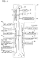
Fig. 4 is a block diagram showing the electrical configuration of the game
machine;
Fig. 5 is a block diagram showing the electrical configuration of a game server;
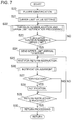
Fig. 6 is a flowchart showing the flow of control of the game machine;
Fig. 7 is a flowchart showing the flow of operation of the game machine;
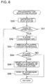
Fig. 8 is a flowchart showing the flow of operation of the game machine when
performing a player identification process;
Fig. 9 is a flowchart showing the flow of operation when the game server
makes preparation for return;
Fig. 10 is a flowchart showing the flow of operation when the game server
executes a return;
Fig. 11 is a flowchart showing the flow of operation when a player sets an
upper limit value on a game machine;
Fig. 12 is a flowchart showing the flow of operation when the game server sets
a return rate; and
Fig. 13 is a diagram of an example of game history tables showing the play
situations of a plurality of game machines that the game server collectively controls.
DETAILS DESCRIPTION OF THE PREFERRED EMBODIMENT
One preferred embodiment of the present invention will be described below in
detail, based on the accompanying drawings.
[Overall Configuration of System]
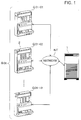
Fig. 1 is a diagram showing, in simplified form, the configuration of a credit
return system according to one preferred embodiment of the invention. Referring to Fig.
1, this credit return system comprises: (i) a game server 1; and (ii) a game machine group
G01 that is a collection of a plurality of game machines 2.
The game machines 2 are connected via a network NT to the game server 1 and
can send to and receive from the game server 1 a variety of information via the network
NT. Individual identification numbers (e.g., G01-01, G01-02, ... G01-10) are assigned
to the individual game machines 2 in the game machine group G01.
The game server 1 collectively controls the game machine group G01 is
comprised of the game machines 2, and identifies or discriminates the source of data sent
from the game machine group G01, based on the identification number being unique to
each game machine 2. On the other hand, when the game server 1 sends data to the
game machine 2, the game server 1 designates the destination (i.e., the game machine 02)
of the data by using the corresponding identification number.
Data sent from and received by the game machine 2 contain: (i) the
identification number being unique to the game machine; and (ii) identification
information to identify the player currently playing with the game machine. Based on
the identification information, the game server 1 determines whether: (i) a game is
performed on the game machine 2; and (ii) there is a player change with the game
machine 2.
Hereinafter, the game server is merely referred to as a "server."
[Mechanical Configuration of Game Machines]
Fig. 2 is a perspective view showing the appearance of a game machine. Fig.
3 is a vertical sectional view of the game machine. Referring to Figs. 2 and 3, a game
machine 2 is a slot game machine (slot machine) and has a frame body 3.
The frame body 3 is in the shape of hollow box. A front panel 4 is attached so
that it is able to open and shut to the frame body 3 via hinges 3A and 3B.
Attached to the rear surface of the front panel 4 is a casing 6, with which three
rotating drums 5 (5A to 5C) arranged across the width thereof are covered from their back
face.
The drums 5A to 5C are of tubular shape and are supported rotatively about
rotary axes 7. Symbol marks (e.g., figure "7", bell, plum, cherry etc.) are respectively
drawn on the peripheral surfaces of the drums 5A to 5C such that the symbol marks are
aligned in a row around their periphery. Of the symbol marks drawn on the peripheral
surfaces of the drums 5A to 5C, one symbol mark per drum is visible from the front side
of the game machine 2 via windows 8A to 8C disposed on the front panel 4.
The rotary axes 7 of the drums 5A to 5C are attached rotatively via bearings
(not shown) to a predetermined bracket (not shown) of the frame of the game machine 2.
One ends of the rotary axes 7 are coupled to output axes of stepping motors 11A to 11C
(see Fig. 4). Therefore, the drums 5A to 5C are rotatively driven by the stepping motors
11A to 11C, respectively, and controlled such that they are stopped at a predetermined
rotational angle position by a control device 12 (see Fig. 4).
Projection parts (not shown) indicating a standard position are disposed on the
peripheral end parts of the drums 5A to 5C. The control device 12 detects the rotational
standard positions of the drums 5A to 5C when these projection parts cross the optical
axes of optical sensors (not shown), which are disposed so as to correspond to the drums
5A to 5C. The rotational speed of the stepping motors 11A to 11C is set so as to make
constant a speed at which symbol marks are displayed while changing.
Bet line indicator lamps 13 are disposed adjacent to the windows 8A to 8C.
The lamps 13 are provided for indicating which line of plural symbol mark stop lines
displayed on windows 8A to 8C has been selected as a bet object.
A control part 14 is located at approximately the mid section of the front panel
4, and a bet button 16 is disposed in the control part 14. The bet button 16 is provided
for setting a bet of medals entered via a throw-in slot 15. When the player pushes the
bet button 16 by the amount of medals on which the player desires to bet, the
corresponding bet line indicator lamp 13 is lit up. The upper limit of bet medals is three
in the game machine 2.
The bet lines are different depending on the number of times the bet button 16
is depressed. By one operation, a single line extending horizontally in the middle stage
of the windows 8A to 8C is the object of bet line. By two operations, the object of bet
line amounts to three lines obtained by adding two lines extending horizontally in the
upper and lower stage of the windows 8A to 8C, to the above-mentioned line. By three
operations, the object of bet line amounts to five lines obtained by adding two lines on the
diagonal of the windows 8A to 8C, to the above-mentioned three lines. Four or more
operations are invalid.
Upon setting a bet medal number according to the above-mentioned procedure,
the control device 12 takes medals corresponding to the bet medal number set by the
player. By taking the medals, the condition of starting slot game is established. In this
state, when the player operates a start lever 17, the control device 12 rotates the drums 5A
to 5C.
The control part 14 has three stop buttons 18A to 18C disposed at locations that
correspond to the drums 5A to 5C, respectively. Upon depressing the stop buttons 18A
to 18C, the corresponding drum is stopped.
The front panel 4 has digital score indicators 19 that indicates, for example, (i)
the number of medals the player threw in for the game; and (ii) the number of medals to
be discharged. When one of predetermined specific combinations of symbol marks
(winning state) in the drums 5A to 5C is aligned on the stop line on which the player bets,
a medal payout device (not shown) is driven to discharge a predetermined number of
medals to a medal payout tray 20.
Further, the front panel 4 has a card inlet 22, through which the player inserts a
card storing an identification number data to identify the player when he/she plays a game
with the game machine 2. A card reader 23 (see Fig. 4) reads the data of the inserted
card.
An upper-limit setting button 42 is disposed in the operation part 14. By
operating this button 42, the player or the provider of the game machine 2 sets an upper
limit value that is the standard for return. Depressing the button 42 to set a desired
upper limit, the upper limit value is displayed on the display part 19. This upper limit
preferably has such a value that the player can consume a day.
[Electrical Configuration of Game Machine]
Fig. 4 is a block diagram showing the electrical configuration of the game
machine. Referring to Fig. 4, the control device 12 of the game machine 2 comprises:
(i) first interface circuit group 31; (ii) input/output bus 32; (iii) CPU 33; (iv) ROM 36; (v)
RAM 37; (vi) random number generator 38; (vii) second interface circuit group 39; and
(viii) communication interface circuit 41.
The bet button 16 is connected to the first interface circuit group 31 being
connected to the input/output bus 32. When the player depresses the bet button 16, an
operation signal is issued from the bet button 16 to the interface circuit group 31. The
interface circuit group 31 converts the operation signal to a predetermined voltage signal
and provides it to the input/output bus 32. Therefore, before starting a game, a
predetermined number of medals corresponding to a value indicated by the operation
signal are thrown into the game machine 2 as the object of bet.
The input/output bus 32 performs input/output of data signals or address signals
to the CPU 33.
The start lever 17 and stop buttons 18A to 18C are connected to the first
interface circuit group 31, on which (i) a start-up signal issued from the start lever 17; and
(ii) a stop signal issued from the stop buttons 18A to 18C, are converted to predetermined
voltage signals and then provided to the input/output bus 32.
When the start lever 17 is operated to start a game, the start-up signal is
provided to the CPU 33. Upon receiving the start-up signal, the CPU 33 issues a control
signal to the stepping motors 11A to 11C in order to rotate the drums 5A to 5C.
When the stop buttons 18A to 18C are depressed to stop the drums 5A to 5C,
the respective stop signals from the stop buttons 18A to 18C are provided to the CPU 33.
If desired to stop the first drum 5A, the player operates the stop button 18A. If desired
to stop the second drum 5B, the player operates the stop button 18B. If desired to stop
the third drum 5C, the player operates the stop button 18C. Upon receiving the stop
signal, the CPU 33 issues the stop signal to the stepping motors 11A to 11C, in order to
stop the drum corresponding to the operated stop button.
Rotational position sensors 34A to 34C are connected to the first interface
circuit group 31. The sensors 34A to 34C are disposed in the vicinity of the stepping
motors 11A to 11C, respectively. The sensors 34A to 34C issue angle position signals
that respectively indicate the rotational angle positions of the stepping motors 11A to 11C,
to the interface circuit group 31. For example, rotary encoders are usable as the
rotational position sensors 34A to 34C.
Standard position sensors 35A to 35C are connected to the first interface circuit
group 31. The sensors 35A to 35C are disposed in the vicinity of the drums 5A to 5C,
respectively. The sensors 35A to 35C are optical sensors as described above, and issue
standard position signals to the interface circuit group 31 when detecting the standard
positions of the drums 5A to 5C.
The card reader 23, which is disposed within the game machine 2, is connected
to the first interface circuit group 31. The card reader 23 issues a card status signal at a
predetermined timing, in accordance with a signal sending demand from the CPU 33.
When a card is inserted into the card inlet 22 (see Fig. 2), for example, the signal level of
the card status signal is higher than a standard level. Based on the change in signal level,
the CPU 33 detects that the card is inserted. On the other hand, when no card is inserted
(i.e., the state that the card has been drawn out from the card inlet 22), for example, the
level of the card status signal returns to the standard level. Based on the change in
signal level, the CPU 33 detects that no card is inserted.
Further, the upper-limit setting button 42 is connected to the first interface
circuit group 31. When a player depresses the upper-limit setting button 42, an
operational signal is issued from the button 42 to the interface circuit group 31. The
interface circuit group 31 converts the operational signal to a predetermined voltage
signal and supplies it to the input/output bus 32. At the result, before a game is started,
a predetermined upper limit value corresponding to the operational signal is set to the
game machine 2, as standard for return.
The CPU 33 detects: (i) an angle position signal issued from the rotational
position sensors 34A to 34C; and (ii) a standard position signal issued from the standard
position sensors 35A to 35C, thereby obtaining data of symbol marks displayed on the
windows 8A to 8C.
The ROM 36 and RAM 37 are connected to the input/output bus 32. The
ROM 36 stores: (i) a program for controlling the game machine and returning medals;
and (ii) an initial value of variable used in the program. The ROM 36 stores data group
indicating correspondence between a combination of symbol marks and random numbers.
The RAM 37 stores flags and variable values.
The communication interface circuit 41 is connected to the input/output bus 32.
The circuit 41 is used when performing sending/receiving of data between the game
machine 2 and server 1.
The random number generator 38 for generating the above random numbers is
connected to the input/output bus 32. When the CPU 33 issues an instruction for
generating random numbers issued to the random number generator 38, the random
number generator 38 generates random numbers in a predetermined range, and issues
signals indicating the random numbers to the input/output bus 32. When a random
number is issued from the random number generator 38, in order to determine a
combination of symbol marks that corresponds to the random number, the CPU 33
searches the above data group and then substitutes a value corresponding to the
combination to variables.
Usually either normal game or special game can be played with the game
machine 2.
In the normal game, there are (i) an enabled prize-winning status that a
combination of symbol marks stopped and displayed on an effective line can match a
prize-winning pattern; and (ii) unabled prize-winning status that a combination of symbol
marks cannot match a prize-winning pattern.
In the unabled prize-winning status, examples of symbol mark combinations
that are changed on effective lines are: (i) failure pattern; and (ii) small prize pattern.
The term "small prize" means that a predetermined number of symbol marks such as
"cherry" and "bell" are aligned on the effective line, and a few medals are discharged to
the payout tray 20. On the other hand, the term "failure pattern" means that symbol
marks are not aligned on any effective line, and no medals are discharged. The unabled
prize-winning status can move to the enabled prize-winning status by an internal lottery
processing to be described later. In the unabled prize-winning status, any prize-winning
pattern cannot be aligned irrespective of a timing at which the stop buttons 18A to 18C
are depressed. Hence, it is impossible to move from the normal game status to the
special play status.
On the other hand, only in the enabled prize-winning status, a combination of
symbol marks stopped and displayed by a timing at which the stop buttons 18A to 18C
are depressed will match a prize-winning pattern. In other words, this state allows for
"aiming (observation push)." When a combination of symbol marks stopped and
displayed on an effective line matches a prize-winning pattern, the player wins a prize and
the game style moves to the special game providing a chance of obtaining a large number
of medals. When the player fails to obtain any prize-winning pattern by missing a
timing of depressing the stop buttons 18A to 18C, the above-mentioned failure pattern or
small prize pattern is aligned on the effective line. If once the enable prize-winning
status is set, this status continues until a combination of symbol marks stopped and
displayed matches a prize-winning pattern. There is no move to the unable
prize-winning status.
In the special game, there is extremely high probability that a combination of
symbol marks stopped and displayed on an effective line will match a small prize pattern.
This leads to a high possibility of obtaining a large number of medals. Upon finishing
the special game, the game style moves to the normal game. When the normal game is
performed after the special game, the determination whether the game proceeds in the
enabled prize-winning status or the unabled prize-winning status is made by an internal
lottery processing to be described later.
The second interface circuit group 39 is also connected to the input/ouput bus
32. To the circuit group 39, there is connected: (i) stepping motors 11A to 11C; (ii) bet
line indicator lamp 13; (iii) score indicator 19; and (iv) speaker 40. The circuit group 39
applies a drive signal or drive power to each of these devices. For instance, when the
player depresses the bet button 16, a drive current is applied to the bet line indicator lamp
13, in order to indicate a bet line that becomes effective in accordance with the number of
throw-in medals. When the game (play) is over, a drive signal is applied to the score
indicator 19, in order to indicate the score corresponding to the prize-winning status.
The speaker 40 issues an effect sound corresponding to the game status when the game is
started or over.
[Configuration of Game Server]
Fig. 5 is a block diagram showing the electrical configuration of the game
server. Referring to Fig. 5, a server 1 has a data bus BUS. To the data bus BUS, there
are connected (i) CPU 51; (ii) memory 52; (iii) communication interface 53; and (iv)
database 54.
The CPU 51 executes various processing according to programs stored in the
memory 52. Concretely, the CPU 51 receives data from the game machine 2 via a
communication line connected by the communication interface 53, and stores the data in
the memory 52. This data contains for example the upper limit data and return rate data
of plural game machines 2 under the control of the server 1, that is, information sent from
each game machine 2 under the control of the server 1. The CPU 51 reads a program
stored in the database 54 on the memory 52, and progresses the program based on the
information sent from each game machine 2 that is stored in the memory 52. The
progress of the program is stored in the database 54.
[Operation of Game Machine]
It is assumed in the following, for purposes of description, that the game
machine 2 is activated in advance, and flags and variables are initialized to a
predetermined value.
Fig. 6 is a flowchart showing the flow of control of game machines. Referring
to Fig. 6, firstly, the CPU 33 with the game machines 2 judges whether the bet button 16
is depressed by the player (step S11). The bet-button operating judgment processing is
executed in accordance with the operation of depressing the bet button 16, and includes
the following processing: (i) detecting whether an operation signal is issued from the bet
button 16 in response to an operation to the bet button 16, thereby storing the number of
throw-in medals with the operation; and (ii) issuing a drive signal to the bet line indicator
lamp 13, in order to indicate the bet line that becomes effective in accordance with the
number of throw-in medals.
Upon completing the bet-button operating judgment processing, the CPU 33
judges whether the pressing operation of the bet button 16 is performed and the operation
of the start lever 17 is performed (step S12). When the CPU 33 judges both operations
are performed, the CPU 33 moves the processing to step S13. On the other hand, when
the CPU 33 judges both are not performed or none of these operations are performed, the
CPU 33 returns the processing to step S11, and performs the bet-button operation
processing again. As will be described later, a period of time that all the drums 5A to
5C are started in rotation and are brought into a stop is a sequence of game (play).
Moving to the processing of step S13, the CPU 33 executes an internal lottery
processing. The internal lottery processing includes processing of: (i) controlling the
random number generator 38 to generate a random number; and (ii) searching data group
indicating the correspondence between combinations of symbol marks and random
numbers, thereby deciding a combination of symbol marks in accordance with the
generated random number. As will be described later, the combination of symbol marks
stopped and displayed on the previous game is stored in the RAM 37. In the following
game, the CPU 33 reads the combination of symbol marks stored in the RAM 37, so that
it is used for internal lottery processing.
In the internal lottery processing, a combination of symbol marks that can be
stopped and displayed is determined by lottery, and a value indicating the lottery result is
substituted for a lottery data of the currently performing game (current game lottery data).
For instance, when it is in the unabled prize-winning status and in failure pattern, the
current game lottery data is set to "00". When it is in the unabled prize-winning status
and there occurs the symbol marks combination matching with a small prize pattern, the
current game lottery data is set to "01". When it is in the enabled prize-winning status,
the current game lottery data is set to "12". When it is in the special play status and in
failure pattern, the current game lottery data is set to "20". When it is in the special play
status and there occurs the symbol marks combination matching with a small prize
pattern, the current game lottery data is set to "21". In an alternative, it may be checked
whether the player has moved to an advantageous state based on the stopped symbol
marks, without performing any internal lottery processing.
Upon completing the processing of step S13, the CPU 33 reads a subroutine
about stepping motor control processing (not shown) and issues, based on the subroutine,
control signals to the stepping motors 11A to 11C, in order to drive each motor at a
predetermined rotational speed (step S14). The term "rotational speed" means a speed
at which the symbol marks are changeably displayed by the rotation of the drums 5A to
5C in the above-mentioned sequence of game (play), and means that any speed in the
transient rotation state, such as of immediately after the drums 5A to 5C starts rotation
and immediately before they are brought into a stop, are excluded from the concept of the
rotational speed.
In this preferred embodiment, there is a lottery data of the game performed in
the past that corresponds to the above-mentioned current game lottery data. The past
game lottery data is data indicating the lottery result of the game performed before the
current game, and the data is stored in the RAM 37. As will be described later, in the
normal game to which the game style moves when the special game is over, the past
game lottery data is reset at the time of performing the fast game. The past game lottery
data is updated by sequentially accumulating the current game result in the previous game
result.
Upon completing the above-mentioned stepping motor control processing, the
CPU 33 judges whether the player depressed any one of the stop buttons 18A to 18C in
order to stop the drums 5A to 5C, and from which stop button a stop signal is issued (step
S15). When the judgment result is that no stop signal is issued from the stop buttons
18A to 18C, the CPU 33 executes again the processing of step S15. On the other hand,
when the judgment result is that a stop signal is issued from any one of the stop buttons
18A to 18C, the CPU 33 performs processing for stopping the stepping motors 11A to
11C (step S16). This stepping motor stop control processing includes: (i) controlling the
random number generator 38 to generate a random number; and (ii) searching data group
indicating the correspondence between combinations of symbol marks and random
numbers, thereby deciding a combination of symbol marks in accordance with the
generated random number.
The CPU 33 obtains symbol marks currently appearing on the windows 8A to
8C, based on (i) a rotational position signal issued from the rotational position sensors
34A to 34C; and (ii) a standard position signal issued from the standard position sensors
35A to 35C. Upon obtaining the symbol marks, the CPU controls the stepping motors
11A to 11C and decides a stop position, based on (i) the above-mentioned symbol mark
data, and (ii) the current game lottery data set in the above-mentioned internal lottery
processing (step S13).
Although the CPU 33 stops the stepping motors 11A to 11C in accordance with
the current game lottery data, if decided that any one of the stop buttons 18A to 18C is
depressed, the CPU 33 can apply an additional drive to the stepping motors 11A to 11C,
under prescribed conditions. Concretely, when any symbol mark corresponding to the
current game lottery data cannot be stopped and displayed, the stepping motors 11A to
11C are subject to an additional drive in the range of the maximum amount of four
symbol marks. In this connection, if any symbol mark corresponding to the current
game lottery data is not present in that range, it is impossible to stop and display any
symbol mark corresponding to the current game lottery data. For instance, even when in
the enabled prize-winning status, two drums are already stopped and there is a symbol
mark(s) allowing for match with a winning pattern, whether the player obtains the
winning pattern depends on the timing at which the player operates the stop button
corresponding to the last drum to be stopped. On the other hand, when in the unabled
prize-winning status, two drums are already stopped and there is a symbol mark(s)
allowing for a winning pattern, the stepping motors 11A to 11C are controlled so as not to
provide a match with the winning pattern, irrespective of the timing of operation of the
stop button corresponding to the last drum to be stopped.
Upon completing the above-mentioned stepping motor stop control processing,
the CPU 33 judges whether all the stop buttons 18A to 18C are depressed (step S17). In
other words, in the processing of step S17, it is judged whether there are detected all the
stop signals issued in accordance with the depressing operation to the stop buttons 18A to
18C. In this connection, when the judgment result is that all of the stop buttons 18A to
18C are not operated, the CPU 33 returns the processing to step S15. On the other hand,
when the judgment result is that all the stop buttons 18A to 18C are operated, the CPU 33
moves the processing to step S18.
Moving to the processing of step S18, the CPU 33 judges whether a
combination of symbol marks aligned on the line that becomes effective matches with a
winning status, and pays out game medals corresponding to the winning status (step S18).
When the judgment result is that (i) the combination of symbol marks aligned in the
effective line and (ii) the wining state are each matched, the CPU 33 calculates the
number of payout medals corresponding to the winning status, and payouts a number of
medals corresponding to the calculated number. Thereafter, the CPU 33 moves the
processing to step S19. On the other hand, when the judgment result is that the
combination of symbol marks aligned in the effective line and the wining state are not
matched, the CPU 33 moves the processing to step S19, without executing any medal
payout.
Moving to the processing of step S19, the CPU 33 mainly stores the current
game lottery data (step S19). In this preferred embodiment, the present subroutine is
terminated at the time that the CPU 33 read a past game lottery data from the RAM 37
and stored the current game lottery data together with the read past game lottery data in
the RAM 37. At this time, for example, data indicating the actually stopped and
displayed symbol marks in the present game is also stored in addition to the present game
lottery data.
Description will next be made of the operation of a game machine 2 of this
preferred embodiment when performing a game with the game machine 2.
Fig. 7 is a flowchart showing the flow of operation of game machines. The
procedure shown in this flowchart is performed concurrently with the subroutine of the
game machines 2 shown in Fig. 6.
Referring to Fig. 7, the game machine 2 discriminates the player (step S20).
This player discrimination processing is performed to judge as to: (i) whether a game is
being performed on the game machine 2; (ii) who the player is, if a game is performed on
the game machine 2; and (iii) whether he/she is the same as or different from the previous
player.
The reason why the player identification (discrimination) processing is
particularly necessary is that a return is executed per player in this preferred embodiment,
unlike the conventional game machine executing a return per game machine. That is,
when there is a player change, the play status about the upper limit till then is reset. It is
therefore necessary to detect a player change and identify (discriminate) the player.
Fig. 8 is a flowchart showing the flow of operation when a game machine
identifies or discriminates the player. This flowchart corresponds to the subroutine of
the player discrimination processing (step S20) shown in Fig. 7.
Referring to Fig. 8, firstly the CPU 33 with game machine 2 judges play status
(step S90). The play status judgment is processing for judging whether there is a player
performing a game on the game machine 2 (i.e., whether a game is being performed on
the game machine 2). When the game machine 2 is not in play status, the following
processing is unnecessary. It is therefore necessary to firstly check whether the game
machine 2 is in play. The play status judgment is achieved by detecting whether a card
is inserted into the card inlet 22 provided on the front panel 4 of the game machine 2.
In order to check the play status, the CPU 33 judges whether a card is detected
(step S91). This card detection is achieved by detecting whether a card is inserted into
the card inlet 22 with the card reader 23. The card to be inserted is an identification card
storing information to identify the player, which can have any function other than
identification. For example, a card (e.g., a prepaid card) storing information to identify
the player can be used.
In step S91, the card detection is performed. At the result, when the judgment
result is that no card is inserted, the CPU 33 terminates the player discrimination
(identification) processing. Thereafter, the CPU 33 sends the server 1 a signal of
discrimination result that no card is detected (step S96). As the contents of signals
related to the card detection, for example, data "0" is sent when no card is detected, and
data "1" is sent when a card is detected.
On the other hand, when the judgment result is that a card is inserted, the CPU
33 identifies the player performing a game on the game machine 2 (step S92). If a card
is already inserted, the card reader 23 reads information stored in the card. In this
preferred embodiment, the card inserted in the card inlet maintains identification number
data individual to the player, in order to identify the player. Therefore, the CPU 33
identifies the player performing a game on the game machine 2, based on the
identification number data.
Upon completing the above-mentioned player identification processing, the
CPU 33 refers to the previous player's history (step S93). Information of the players
who have been played on the game machine 2 is stored, as history, in the RAM 37 of the
game machines 2. The CPU 33 refers to the player's history stored in the RAM 37, and
refers to the identification number of the player immediately before receiving a signal
indicating that a card has been detected.
Upon completing the reference to the immediately-before-player history, the
CPU 33 judges whether there is player change (step S94). The CPU 33 compares (i) the
identification number data of the previous player that has been referred to in step S93;
with (ii) the identification number data of the player that has been sent from the card
reader 23 together with the card detection signal, thereby judging whether there is
agreement between the two. If the two data agree, the CPU 33 judges that there is no
player change, because the same player merely inserted the identification card again. If
the two data are different, the CPU 33 judged that there is player change. In the absence
of no player change, the CPU 33 completes the player discrimination processing. On the
other hand, in the presence of player change, the CPU 33 resets the cumulative throw-in
number of the previous player (step S95). Concretely, the CPU 33 resets data related to
the cumulative throw-in number of credit consumed by the previous player, in the
player's history stored in the RAM 37 that has been referred to in step S93.
This reset processing is for implementing one of the characteristic features of
this preferred embodiment, that is, performing a "return" per player. This means that the
cumulative throw-in number of credit cannot be increased by addition to the credit
number thrown by the other player. Therefore, if a certain player stops a game on one
game machine before reaching the upper limit of the cumulative throw-in number of
credit, and moves to the other game machine, this player will start a game on the other
game machine from the status that the cumulative throw-in number of credit returns to
"0". Thereby, the player might not often change game machines. In addition, the
player is aware that there is a high probability of return when reaching the upper limit of
the cumulative throw-in number. This makes it possible to continue the game without
anxiety.
Upon completing the above-mentioned reset processing, the CPU 33 with the
game machine 2 sends the result of judgment made in step S90 (step S96). Concretely,
the CPU 33 sends the player's information to the server 1 via the communication
interface circuit 41, network NT, and communication interface 53 of the server 1. Data
to be sent may be the player's information to which value "1" is appended, as stated
above. At this time, in the CPU 33, the past player's history information stored in the
RAM 37 is rewritten to the new player's information and then stored.
Upon completing the judgment result sending processing, the CPU 33 repeats
the player discrimination processing.
Although in this preferred embodiment, an identification card storing data to
verify the player or an ID card is used as means for identifying or discriminating the
player, the following means are applicable. For example, a human sensor to detect
human body may be attached to the game machine 2. To a stool on which the player sits
for performing a game, the function of weighing may be added for weighing and storing
the player's body weight, thereby discriminating the player.
Referring again to Fig. 7, upon completing the above-mentioned sequence of
player identification (discrimination) processing, the CPU 33 with the game machine 2
sets an upper limit value that is a standard for return (step S21). The upper limit value
is the number of medals, as a game medium, which is used for performing a game on a
slot game machine etc. When the number of medals used by a certain player reaches the
upper limit value, the slot game machine executes a return to this player.
The above-mentioned upper limit value setting is attainable in the following
various instances: (i) the upper limit setting is performed by using a preset upper limit
value; (ii) the owner of the game machine performs the upper limit setting; or (iii) the
upper limit value is automatically changed depending on the play status. The upper
limit value setting executable in the above various instances is to be performed when the
game player of the game machine 2 is changed, and after referring to the result of
judgment whether there is a player change in step S21. The result of judgment whether
there is player change is made into data and sent from the server 1 to the game machine 2.
Concretely, in the presence of player change, data to which value "1" is appended is sent.
On the other hand, in the absence of player change, data to which value "0" is appended
is sent.
Following is the style of using a preset upper limit value, which is one of the
above-mentioned various styles. The style of setting an upper limit value by the
operation of a player will be described hereafter.
The preset upper limit value is stored in the RAM 37. The CPU 33 reads data
of the upper limit value from the RAM 37 and completes setting of the upper limit value.
Upon completing the above-mentioned upper limit value set processing, the
CPU 33 performs, based on the result of the bet button operation processing (step S11)
shown in Fig. 6, processing for (i) adding the number of medals thrown by the player as a
game medium; and (ii) notifying the upper limit (step S22).
A description of throw-in number addition processing will be presented here.
A medal sensor (not shown) provided within the game machine 2 counts medals thrown
in through the throw-in slot 15. The counted number data is added to a cumulative
throw-in number data, which is data of medals thrown in the past, and stored as a current
throw-in medal data. Hereinafter, the cumulative consumption of credit is referred to as
a "cumulative throw-in number of medals."
The above-mentioned cumulative throw-in number data is data stored in the
RAM 37. The CPU 33 executes the following processing for reading data of the past
throw-in medal from RAM 37; adding data of the current throw-in medal counted by the
medal sensor to data of the cumulative throw-in number; and storing the result of addition
as updated cumulative throw-in number data in the RAM 37. The cumulative throw-in
number data is reset in the presence of player change, as previously described in the
player discrimination processing.
A description of upper limit notification processing will next be presented.
The upper limit notification means to notify the player how soon the game machine 2 can
reach the upper limit. Specific contents of the notification include: (i) the set upper limit
value; (ii) the current cumulative throw-in number; or (iii) the rate of the cumulative
throw-in number to the upper limit value (i.e., one that is expressed by percentage how
close to the upper limit).
By virtue of this notification, the player can know to what extend he/she has to
perform a game up to the upper limit. Therefore, the player can continue the game
without anxiety.
Upon completing the above-mentioned throw-in medal number addition
processing and upper-limit notification determination processing, the CPU 33 judges
whether the cumulative throw-in number reaches the upper limit (step S23). This
judgment is achieved by comparing (i) the cumulative throw-in number data that was
stored in the RAM 37 in step S22; and (ii) the upper limit value that was set in step S21.
Concretely, the CPU 33 compares these two data stored in the RAM 37 and judges
whether the number of medals that the play throws in the game machine 2 reaches the
upper limit. When the judgment result is that the cumulative throw-in number does not
reach the upper limit value, the CPU 33 returns the processing to step S22, and continues
processing for adding the number of medals that the player throws in the game machine 2.
On the other hand, when the judgment result is that the cumulative throw-in number
reaches the upper limit value, the CPU 33 notifies the player of the arrival at the upper
limit, and sends the upper limit arrival result to the server 1 (step S24). Concretely, the
CPU 33 sends (i) a signal indicating that the cumulative throw-in number reaches the
upper limit value; (ii) data of the upper limit value set in step S21; and (iii) data of return
rate to be described later, to the server 1 via the communication interface circuit 41 of the
game machine 2.
The signal indicating arrival at the upper limit is expressed for example by
numerical value of "1". To the signal indicating that the cumulative throw-in number
data reaches the upper limit, a signal designating the game machine 2 is appended (i.e.,
data indicating to which of plural game machines under the control of the server 1 the
game machine 2 corresponds). For example, if an identification number, the numbers
"123", is assigned to the game machine 2 among plural game machines under the control
of the server 1, a signal of "123-1", wherein the numerical value "1" as the signal
indicating arrival at the upper limit is affixed to the identification number "123" of the
game machine 2, is sent to the sever 1.
The upper limit value data is stored in the RAM 37, as described above. This
upper limit value data is used for determining the number of return medals on the
occasion where a return must be executed to the player. The number of return medals is
calculated by multiplying the upper limit value by a return rate.
The RAM 37 with the game machine 2 stores return rate data for determining to
what extent the return is to be executed with respect to the upper limit value of the game
machine 2 at the arrival at the upper limit. This return rate data is sent from the game
machine 2 to the server 1.
Upon completing the upper-limit-arrival result sending processing to the server
1, the CPU 33 waits for a return instruction (step S25). The return instruction is a signal
to be sent from the server 1 to the game machine 2 of which cumulative throw-in number
data reaches the upper limit, and this signal is used for controlling the timing of return etc.
The game machine 2 allows the player to perform a game even when waiting for the
return instruction.
In the above-mentioned return instruction waiting status, the CPU 33 judges
whether notification should be executed or not (step S26). The term "notification"
means to notify that a return will be executed from now to the player of the game
machine 2.
By referring to the data stored in the RAM 37, the CPU 33 determines as to
whether this notification should be executed (step S27). The RAM 37 stores data for
determining execution of notification. Concretely, data of "1" is assigned for execution
of notification, and data of "0" is assigned for no execution of notification. These data
may be preset or set properly by the owner of the game machine etc.
When the data stored in the RAM 37 is "1", the CPU 33 notifies the player the
content that the cumulative throw-in medal number of the game machine 2 on which
he/she is performing a game will reach the upper limit thereby to execute a return shortly
(step S28). This notification may be executed by using an illuminator provided within
the game machine 2. Alternatively, the game machine 2 may have a display part
performing notification to the player. Any notification means capable of giving the
player a previous notice of return may be employed, whether it be provided unitary with
the game machine 2.
When the above-mentioned notification processing is completed, or when
judged no notification is executed, the CPU 33 judges whether a return instruction is
received (step S29). This return instruction is one that the game machine 2 waits for its
arrival from the server 1 in step S25. The server 1 sends this return instruction without
fail to a game machine 2 employing the style that a return is executed every time the
game machine 2 reaches the upper limit, as well as a game machine 2 employing the style
that a return is not always executed to the game machine 2 when it reaches the upper
limit.
The server 1 sends a return instruction signal at a predetermined timing to the
game machine 2 via the communication interface 53. In the game machine 2, the CPU
33 receives the return instruction via the communication interface circuit 41 and
input/output bus 32. If failed to receive the return instruction, the CPU 33 returns the
processing to step S25, and waits for the return instruction again.
Upon completing the above-mentioned return instruction receiving processing,
the CPU 33 executes return processing (step S30). This return processing is executed
based on the return instruction issued from the server 1 in step S29. Concretely, the
CPU 33 receives data that indicates to what extent the return should be executed to the
game machine 2, and executes a return based on the received data.
In the game machine 2 employing the style that a return is executed every time
the throw-in medal number reaches the upper limit, a number of medals are returned
which is calculated mainly based on the upper limit data and return rate data stored in the
RAM 37. On the other hand, in the game machine 2 employing the style that a return is
not always executed when the throw-in medal number reaches the upper limit, if decided
to execute no return, the throw-in number data stored in the RAM 37 is reset as required.
The CPU 33 executes this throw-in number data reset under a program stored in the ROM
36.
Upon completing the above-mention return processing, the CPU 33 moves
again the processing to the upper-limit value setting processing (step S21), and repeats
the above-mentioned sequence of processing.
[Operation of Game Server]
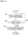
Fig. 9 is a flowchart showing the flow of operation when the game server
makes preparation for return. This operation is always repeated in the server 1.
The server 1 always holds some of medals serving as a game medium, which
have been thrown in each game machine 2, in preparation for execution of return to the
game machine 2 under the control of the server 1 reaches the upper limit.
Referring to Fig. 9, the CPU 51 with the server 1 waits for the game medium
throw-in result from each game machine 2 (step S41).
As the game medium that the player uses on each game machine 2, it is
possible to use any tangible matters, e.g., medals, winning balls, or coins, each being used
generally. Besides these, any intangible matters that can be expressed in numerical
value as data are also handled as a game medium in this preferred embodiment. The
term "throw-in" means the following action that a certain player makes a game machine
recognize the game medium for the purpose of playing a game, irrespective of the type of
the game medium. Therefore, not only a medal etc. that is thrown in through the
throw-in slot 15 and detected by the medal sensor of the game machine 2, but also
numerical value data etc. that the player decides to use for game becomes a candidate for
wait.
In the status that the server 1 is waiting for throw-in of a game medium, the
CPU 51 judges whether game medium throw-in data is received at a predetermined
timing (step S42). In this preferred embodiment, medals are used as the game medium,
and the player continues the game on the game machine 2, while throwing in medals via
the throw-in slot 15. The medal sensor with the game machine 2 detects the number of
thrown-in medals. The detected number is made into a numerical value as data. This
data is then stored in the RAM 37 of the game machine 2, as cumulative throw-in number
data. This cumulative throw-in number data is sent at a predetermined timing to the
server 1 via the communication interface circuit 41. The server 1 receives this
cumulative throw-in number data via the communication interface 53. The received
cumulative throw-in number data is properly stored in the memory 52, based on an
instruction of the CPU 51. When the judgment result in step 42 is that no throw-in data
is received, the CPU 51 returns the processing to step S41.
Upon completing the throw-in data receiving judgment processing, the CPU 51
holds a predetermined rate of the throw-in number (step S43). As stated above, the
server 1 is constructed so as to hold in advance the game medium for return to the player
performing a game on each game machine 2 under the control of the server 1. The hold
amount differs from one server to another. The hold amount is determined by
multiplying the cumulative throw-in number data of each game machine 2 that the server
1 receives in step S42, by a predetermined rate (return rate).
In the above-mentioned hold processing, the server 1 sends a numerical value
data corresponding to the hold amount calculated by the CPU 51, to the game machine 2
via the communication interface 53. On the game machine 2, based on the received
numerical value data, the CPU 33 directs the RAM 37 to store, as hold data, a numerical
value data that is part of the cumulative throw-in number data.
Upon completing the above-mentioned hold processing, the CPU 51 returns the
processing to the throw-in data waiting processing (step S41), and repeats the foregoing
sequence of processes.
A description will next be made of the operation when the server 1 executes a
return to the game machine 2 under control of the server 1.
Fig. 10 is a flowchart showing the flow of operation when the game server
executes a return. This operation is always repeated.
Referring to Fig. 10, firstly, the CPU 51 with the server 1 performs a lottery for
determining a return destination (step S51). This return destination lottery is mainly
performed to the case of taking the style that a return is not necessarily executed to the
game machine 2 that has reached the upper limit. As the lottery manner, there are for
example: (i) "a return is executed to a game machine that will be the N-th to reach the
upper limit"; and (ii) "a return is executed to a game machine, the end of which
machine-number meets a lottery-number." Whereas in the case of taking the style that a
return is always executed to the game machine reaching the upper limit, the result
obtained by lottery can be exemplified as follows: (i) "a return is executed to a game
machine that will be the fast to reach the upper limit; and (ii) "a return is executed to
game machines, the end of which machine-number is 0, 1, ... 9 (i.e., to designate all the
machine-numbers)." These lottery results are stored in the memory 52, based on an
instruction of the CPU 51.
Upon completing the above-mentioned return destination lottery processing, the
CPU 51 waits for the upper limit arrival result sent from each game machine 2 (step S52).
As stated above, this upper limit arrival result indicates that the game medium thrown in
the game machine 2 reaches a preset amount. Upper limit arrival judgment is made on
the game machine 2. At the result, when the judgment result is the arrival at the upper
limit, this result is sent to the server 1 waiting for the upper limit arrival result via the
communication interface 53.
When the server 1 is waiting for the upper limit arrival result, the CPU 51
judges whether it received the upper limit arrival result at a predetermined timing (step
S53). The CPU 51 executes this judgment. When the judgment result is that the upper
limit arrival result is received, the CPU 51 moves the processing to the step S54. On the
other hand, the judgment result is that any upper limit arrival result is not received, the
CPU 51 returns to the upper limit arrival result wait processing (step S52), and repeats
judgment of the receipt of the upper limit arrival result at the predetermined timing.
Moving to the processing of step S54, the CPU 51 judges whether the game
machine 2 sending the upper limit arrival result is a return destination. This judgment is
made based on the data determined by the data obtained in the lottery in step S51.
Concretely, the CPU 51 refers to the data stored in the memory 52; and judges whether it
is the return destination by comparing (i) this reference data and (ii) data affixed to the
upper limit arrival result.
For example, when the lottery result is that "a return is executed to a game
machine, the end of which machine-number meets a lottery number," as described above,
the CPU 51 reads data of the identification number of the game machine 2 that is affixed
to the above lottery result, and then judges whether the end of the identification number
meets the above lottery number. In the case of taking the style that a return is always
executed for the upper limit arrival, a positive result is always obtained in the judgment
whether it is the return destination.
When the judgment result is negative, a signal indicating no execution of return
is sent in the processing for sending a return control signal that will be described later.
This signal is sent to the game machine 2 via the communication interface 53, based on
an instruction of the CPU 51.
Upon obtaining a positive result in the above-mentioned return destination
judgment processing, the CPU 51 judges a return timing (step S55).
The return timing can be set variously. There is for example the following
styles: (i) to the game machine reaching the upper limit and being the return destination, a
forced return is executed immediately after all the processes on the server 1 are
terminated; and (ii) a return is executed after an elapse of a predetermined period of time
from the termination of all the processes on the server, or after performing a
predetermined number of games.
The processing for judging a return timing is to judge at which timing a return
should be executed. If a return timing is predetermined uniquely, this return timing is
employed.
Upon completing the above-mentioned return timing judgment processing, the
CPU 51 judges whether a return timing is established (step S56). The term "return
timing" is one that is determined in the processing of step S55, and this return timing is
stored in the memory 52 with the server 1. For instance, if provided a temporal timing
such as "at a few minutes after the upper limit arrival," a timer (not shown) within the
server 1 is used to control this timing. If provided a timing based on the player's game
circumstances such as "when the player performs twenty games after reaching the upper
limit," various sensors within the game machine 2 are used to judge whether
predetermined conditions are satisfied. When the conditions are satisfied, a signal
indicating this timing is sent from the CPU 33 with the game machine 2 to the server 1, in
order to notify the incoming of the return timing.
When the judgment result is that no return timing is established, the CPU 51
returns the processing to step S55, and repeats the processing from step S55. On the
other hand, when the judgment result is that the return timing is established, the CPU 51
refers to the game medium amount (number) etc. held in step S43 (see Fig. 9) and
determines the amount of return based on the reference result (step S57).
The amount of return to the game machine 2 is to be managed by the game
media held in step S43. Arriving at the upper limit, a return is usually executed by
multiplying the upper limit value by a preset return rate. As a general rule, the CPU 51
calculates the return amount based on the upper limit data and return rate data that are
contained in the upper limit arrival result sent from the game machine 2.
Upon completing the above-mentioned return amount determination processing,
the CPU 51 sends a return control signal to the game machine 2 (step S58). This return
control signal can be classified into two types, according to the result of the
above-mentioned return destination judgment processing (step S54). Concretely, with
respect to a game machine 2 that was judged as the return destination in step S54, the
value of "1", which is data indicating that this game machine 2 is the return destination, is
affixed to part of a return control signal. On the other hand, with respect to a game
machine 2 that was not judged as the return destination, the value of "0", which is data
indicating that this game machine 2 is not the return destination, is affixed to part of a
return control signal. In the case of taking the style that a return is always executed to
the game machine reaching the upper limit, the value of this return control signal is set to
"1".
The return control signal contains data indicating the degree (amount) of return.
All the data contained in this return control signal are sent via the communication
interface 53, based on an instruction of the CPU 51.
Upon completing the above-mentioned control signal sending processing, the
CPU 51 subtracts a hold number (step S59). The term "hold number" means the game
medium number held in the memory 52 with the server 1 in step S43 shown in Fig. 9.
This hold game medium is used for return to each game machine 2. It is therefore
necessary to perform subtract processing of the game medium number data corresponding
to the return amount.
The hold number data is updated and stored in the memory 52 by the hold
number subtraction processing.
In the case of changing the return amount to a game machine 2 depending on
the play status, there may be configured such that when the return to the game machine 2
is completed, the CPU 33 with the game machine 2 sends the server 1 data indicating the
return amount to the player and subtraction processing is started after receiving this data.
Upon completing the above-mentioned hold number subtraction processing, the
CPU 51 returns the processing to step S51, and resumes the processing from the return
destination lottery and later processing.
Following is the processing for setting an upper limit value by the player's
operation.
[Processing for setting upper limit value]
As stated above, when the cumulative credit consumption of a player reaches a
predetermined upper limit in the individual game machines under collective control of the
game server, a return is executed as a general rule. At this time, if the predetermined
upper limit as standard for return is too high, the return is less likely to occur. Therefore,
the player might give up the game. On the other hand, if the predetermined upper limit
is too low, the game machine is poor in game characteristics. To overcome these
drawbacks, a predetermined upper limit value as standard for return can be set by the
player's operation in this preferred embodiment.
Fig. 11 is a flowchart showing the flow of operation when a player sets an
upper limit value on a game machine. This flowchart corresponds to the subroutine of
the upper limit setting processing in step S21 shown in Fig.7. The processing shown in
Fig. 11 is performed on the game machine 2 under collective control of the server 1.
Referring to Fig. 11, the CPU 33 with the game machine 2 firstly waits for the
operation of the upper-limit setting button 42 (step S61).
As described above, the player performing a game on the game machine 2
depresses the upper-limit button 42 to set an upper limit value. The upper limit value
changes depending on the number of depressions, as will be described later.
At a predetermined timing, the CPU 33 judges whether the upper-limit setting
button 42 is depressed (step S62). When the judgment result is that the upper-limit
button 42 is not depressed, the CPU 33 returns the processing to step S61 and waits for
the button depression by the player of the game machine 2. On the other hand, when the
judgment result is that the upper-limit setting button 42 is depressed, the CPU 33 detects
the number of depressions (step S63). The button 42 issues a signal corresponding to
the depression operation. The CPU 33 receives this signal to detect the number the
player depressed the button 42. The detected depression number is then stored in the
RAM 37.
Upon completing the depression number detection, the CPU 33 moves to the
processing for calculating the upper limit value based on the following arithmetic
expression (step S64):
Upper limit value = (Number of upper-limit setting button depressions) × 5
The depression number of the upper-limit setting button 42 that is detected in
step S63 is used for setting an upper limit value. In this preferred embodiment, the
upper limit value that the player set is indicated at the result obtained by multiplying the
depression number by 5 (in thousands of yen). The processing for calculating the upper
limit value is executed under a program stored in the ROM 36.
In this preferred embodiment, the aforesaid numerical value by which the
depression number is multiplied, "5", is for purpose of illustration only and is not to be
construed as a limiting value.
Upon completing the upper-limit calculation processing (i.e., calculation from
the expression of (Number of upper-limit setting button depression) × 5)), the CPU 33
sends the result from the arithmetic expression (step S65).
The result of the upper limit calculation is sent to the server 1 via the
communication interface circuit 41, network NT, and communication interface 53.
Under instruction of the CPU 51, the server 1 registers this result in the history table (see
Fig. 13) stored in the database 54. The operation of registering the upper limit
calculation result is performed per game machine.
Upon completing the sending of the upper limit calculation result, the CPU 33
waits for a display signal (step S66). The display signal is a signal sent from the server
1, in order that before the processing of step S64, the upper limit value set by the player is
displayed on the display part 19 of the game machine 2.
At a predetermined timing, the CPU 33 judges whether the display signal is
received (step S67). When the judgment result is that no display signal is received, the
CPU 33 returns the processing to step S66 and waits for the display signal again. On the
other hand, when the judgment result is that the display signal is received, the CPU 33
displays the upper limit value (step S68). In order to display the upper limit value, the
CPU 33 applies a drive signal via the interface circuit group 39 to the display part 19, so
that the upper limit is displayed on the display part 19.
Upon completing the upper limit display processing, the CPU 33 terminates the
present subroutine.
With the above configuration, the player performing a game on the game
machine 2 can set an upper limit value at his/her desire. At the result, the player can
enjoy the game without anxiety.
Additionally, in this preferred embodiment a return rate that is the standard for
return is determined by the upper limit value that the player set. Following is the
processing for determining a return rate.
Following is the processing for setting a return rate.
[Processing for Setting Return Rate]
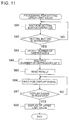
Fig. 12 is a flowchart showing the flow of operation when the game server sets
a return rate. This flowchart corresponds to the subroutine of the return rate setting in
step S57 shown in Fig. 10. The processing shown in Fig. 12 is performed on the server
1 that collectively controls a plurality of game machines 2.
Referring to Fig. 12, the CPU 51 with the server 1 firstly refers to a history
table shown in Fig. 13 (step S71). The history table is one in which the play statuses on
the individual game machines 2 and a variety of settings are registered, and which is
stored in the database 54 with the server 1. Referring to Fig. 13, this history table has
the following contents: (i) machine-numbers of the game machines 2 under collective
control of the server 1; (ii) the upper limit values being individual to these game
machines 2; (iii) data indicating whether the cumulative credit consumption of each game
machine 2 reaches the upper limit; (iv) return rates; and (v) the amount of return to be
executed.
In order to specify a game machine 2 to which a return number is set, data of
machine-number sent from the game machine 2 is necessary. As data of
machine-number, there is used a signal sent from the communication interface circuit 41
via network NT and communication interface 53 when judging whether it is a return
timing, in step S56 shown in Fig. 10.
Upon completing the history table reference processing, the CPU 51 refers to an
upper limit value registered in the history table (step S72). The processing for referring
to the upper limit value is to refer to the numerical data in the column "upper limit (in
thousands of yen)" on the history table. As will be described later, in this preferred
embodiment a return rate is determined by the upper limit value, so as to execute a return
according to the upper limit value set by the player. Therefore, the player can adjust
gamble characteristics of a game at his/her desire.
Upon completing the upper limit reference processing, the CPU 51 judges
whether a first predetermined standard of the upper limit value is not less than 10 (in
thousands of yen), for example (step S73).
In the first predetermined standard judgment processing in step S73, when the
judgment result is that the upper limit value set by the player is lower than the first
predetermined standard, the CPU 51 moves the processing to step S78, and sets the return
rate to a first value (e.g., a value not more than 20 %). That is, the CPU 51 performs a
lottery for selecting one numerical value from data containing various numerical values of
not more than "20". The selected numerical value data is set as a return rate to the game
machine.
Upon completing the processing for setting the return rate to the first value, the
CPU 51 displays the return rate (step S77). This return rate display processing is
achieved by sending a signal for indicating the return rate to the display part 19 of the
game machine 2 via the communication interface 53 with the server 1, network NT, and
communication interface circuit 41 with the game machine 2.
When the judgment result of step S73 is that the upper limit value set by the
player is not less than the first predetermined standard, the CPU 51 moves the processing
to step S74, and judges whether the upper limit value is not more than a second
predetermined standard (e.g., 50 (in thousands of yen)).
When the judgment result of step S74 is that the upper limit value set by the
player is lower than the second predetermined standard, the CPU 51 moves the
processing to step S79, and sets the return rate to a second value (e.g., a value ranging
from not less than 20 % to not more than 40 %). That is, the CPU 51 performs a lottery
for selecting one numerical value from data containing various numerical values of not
less than "20" to not more than "40". The selected numerical value data is set as a
return rate to the game machine.
Upon completing the processing for setting the return rate to the second value,
the CPU 51 displays the return rate (step S77).
When the judgment result of step S74 is that the upper limit value set by the
player is higher than the second predetermined standard, the CPU 51 moves the
processing to step S75, and judges whether the upper limit value is not less than a third
predetermined standard (e.g., 100 (in thousands of yen)).
When the judgment result of step S75 is that the upper limit value set by the
player is lower than the third predetermined standard, the CPU 51 moves the processing
to step S80, and sets the return rate to a third value (e.g., a value ranging from not less
than 30 % to not more than 50 %). That is, the CPU 51 performs a lottery for selecting
one numerical value from data containing various numerical values of not less than "30"
to not more than "50". The selected numerical value data is set as a return rate to the
game machine.
Upon completing the processing for setting the return rate to the third value, the
CPU 51 displays the return rate (step S77).
When the judgment result of step S75 is that the upper limit value set by the
player is higher than the third predetermined standard, the CPU 51 moves the processing
to step S76, and sets the return rate to a fourth value (e.g., a value not less than 50 %).
That is, the CPU 51 performs a lottery for selecting one numerical value from data
containing various numerical values of not less than "50" (it may be a numerical value of
not less than "100"). The selected numerical value data is set as a return rate to the
game machine.
When a player sets a high upper limit value by selecting a numerical value from
the range of not less than "100", there is the possibility that the player can receive a return
over the upper limit, thus further increasing game characteristics.
Upon completing the processing for setting the return rate to the fourth value,
the CPU 51 displays the return rate (step S77).
By checking the return rate displayed on the display part 19 of the game
machine 2, the player can confirm the amount of a return to be executed when the
cumulative credit consumption of the player reaches the upper limit that the player set to
the present game machine. At the result, the player can continue the game without
anxiety.
Upon completing the processing for displaying the return rate, the CPU 51
terminates the foregoing sequence of return rate setting processes.
[Operations and Effects]
This preferred embodiment produces mainly the following operations and
effects.
While but one embodiment of the invention has been shown and described, it
will be understood that many changes and modifications may be made therein without
departing from the spirit or scope of the present invention.