EP1304396A1 - Legierungspulver zur Beschichtung sowie Beschichtungsverfahren - Google Patents
Legierungspulver zur Beschichtung sowie Beschichtungsverfahren Download PDFInfo
- Publication number
- EP1304396A1 EP1304396A1 EP02019625A EP02019625A EP1304396A1 EP 1304396 A1 EP1304396 A1 EP 1304396A1 EP 02019625 A EP02019625 A EP 02019625A EP 02019625 A EP02019625 A EP 02019625A EP 1304396 A1 EP1304396 A1 EP 1304396A1
- Authority
- EP
- European Patent Office
- Prior art keywords
- alloy powder
- coating
- weight
- aluminum
- alloy
- Prior art date
- Legal status (The legal status is an assumption and is not a legal conclusion. Google has not performed a legal analysis and makes no representation as to the accuracy of the status listed.)
- Granted
Links
Images


Classifications
-
- C—CHEMISTRY; METALLURGY
- C22—METALLURGY; FERROUS OR NON-FERROUS ALLOYS; TREATMENT OF ALLOYS OR NON-FERROUS METALS
- C22C—ALLOYS
- C22C32/00—Non-ferrous alloys containing at least 5% by weight but less than 50% by weight of oxides, carbides, borides, nitrides, silicides or other metal compounds, e.g. oxynitrides, sulfides, whether added as such or formed in situ
- C22C32/0047—Non-ferrous alloys containing at least 5% by weight but less than 50% by weight of oxides, carbides, borides, nitrides, silicides or other metal compounds, e.g. oxynitrides, sulfides, whether added as such or formed in situ with carbides, nitrides, borides or silicides as the main non-metallic constituents
-
- C—CHEMISTRY; METALLURGY
- C22—METALLURGY; FERROUS OR NON-FERROUS ALLOYS; TREATMENT OF ALLOYS OR NON-FERROUS METALS
- C22C—ALLOYS
- C22C32/00—Non-ferrous alloys containing at least 5% by weight but less than 50% by weight of oxides, carbides, borides, nitrides, silicides or other metal compounds, e.g. oxynitrides, sulfides, whether added as such or formed in situ
-
- C—CHEMISTRY; METALLURGY
- C23—COATING METALLIC MATERIAL; COATING MATERIAL WITH METALLIC MATERIAL; CHEMICAL SURFACE TREATMENT; DIFFUSION TREATMENT OF METALLIC MATERIAL; COATING BY VACUUM EVAPORATION, BY SPUTTERING, BY ION IMPLANTATION OR BY CHEMICAL VAPOUR DEPOSITION, IN GENERAL; INHIBITING CORROSION OF METALLIC MATERIAL OR INCRUSTATION IN GENERAL
- C23C—COATING METALLIC MATERIAL; COATING MATERIAL WITH METALLIC MATERIAL; SURFACE TREATMENT OF METALLIC MATERIAL BY DIFFUSION INTO THE SURFACE, BY CHEMICAL CONVERSION OR SUBSTITUTION; COATING BY VACUUM EVAPORATION, BY SPUTTERING, BY ION IMPLANTATION OR BY CHEMICAL VAPOUR DEPOSITION, IN GENERAL
- C23C24/00—Coating starting from inorganic powder
- C23C24/08—Coating starting from inorganic powder by application of heat or pressure and heat
- C23C24/10—Coating starting from inorganic powder by application of heat or pressure and heat with intermediate formation of a liquid phase in the layer
-
- C—CHEMISTRY; METALLURGY
- C23—COATING METALLIC MATERIAL; COATING MATERIAL WITH METALLIC MATERIAL; CHEMICAL SURFACE TREATMENT; DIFFUSION TREATMENT OF METALLIC MATERIAL; COATING BY VACUUM EVAPORATION, BY SPUTTERING, BY ION IMPLANTATION OR BY CHEMICAL VAPOUR DEPOSITION, IN GENERAL; INHIBITING CORROSION OF METALLIC MATERIAL OR INCRUSTATION IN GENERAL
- C23C—COATING METALLIC MATERIAL; COATING MATERIAL WITH METALLIC MATERIAL; SURFACE TREATMENT OF METALLIC MATERIAL BY DIFFUSION INTO THE SURFACE, BY CHEMICAL CONVERSION OR SUBSTITUTION; COATING BY VACUUM EVAPORATION, BY SPUTTERING, BY ION IMPLANTATION OR BY CHEMICAL VAPOUR DEPOSITION, IN GENERAL
- C23C26/00—Coating not provided for in groups C23C2/00 - C23C24/00
- C23C26/02—Coating not provided for in groups C23C2/00 - C23C24/00 applying molten material to the substrate
Definitions
- the invention relates to an alloy powder for coating an aluminum alloy in particular existing component, in particular the valve seat area of a cylinder head an internal combustion engine.
- the invention relates to a method for coating such Component by means of a high-energy beam.
- valve seat area in particular one made of an aluminum alloy existing cylinder head in particular with regard to strength, resilience and to optimize abrasion and wear resistance, it is known, accordingly use robust valve seat rings.
- DE 197 describes 21 406 A1 a valve seat, which fits into an aluminum or aluminum cylinder head Aluminum alloy inserted and / or connected to it.
- valve seat especially due to large temperature fluctuations over one wide range and the associated thermal expansion as well as the high Load is very critical, so you switched to instead of Valve seat rings a direct coating of the seat on the cylinder head make.
- EP 843 022 A1 which relates to Process for forming a valve seat by means of thermal spray coating.
- the object of the invention is to provide a coating material and a method to provide its application, thereby avoiding the aforementioned Disadvantages of a valve seat area with a particular hardness without a tendency to Cracking is provided.
- the coating produced is said to be a good one Wear resistance at high temperatures, high hardness and strength, have good thermal conductivity and lubrication.
- the alloy powder advantageously contains aluminum (Al) 10-70% by weight, in particular 20-50% by weight silicon (Si) and 5-50% by weight, in particular 10-40 wt .-% titanium (Ti), corresponding to the Si or Ti content the hardness within wide limits - for example up to over 550 HV with AlSi50Ti30 - is controllable without an increased tendency to form cracks.
- the alloying element titanium is used to refine the grain from the Melt deposited silicon primary crystals, so that despite one high grain content small grain sizes are present.
- the alloy powder also contains up to 25% by weight, in particular 1-15% by weight of nickel (Ni) and / or up to 20% by weight, in particular 1-10 wt .-% copper (Cu) contain.
- a particular advantage results from the addition of high-temperature lubricants to the alloy powder, boron nitrite (BN), graphite, B 2 O 3 and / or Co / Cr 2 O 2 being present in a proportion by weight of up to 20%, in particular 5- 10% have shown to be very suitable.
- boron nitrite (BN), graphite, B 2 O 3 and / or Co / Cr 2 O 2 being present in a proportion by weight of up to 20%, in particular 5- 10% have shown to be very suitable.
- the pocket-like islands of lubricant continuously formed in the layer are exposed again and again due to operational wear, so that a permanent lubricating effect is achieved over the service life.
- the alloy powder also contains hard material particles.
- Fig. 1 shows a micrograph of an using an aluminum-silicon powder coated component made of an aluminum alloy.
- This type of coating is used to technology in particular Wear resistance of an aluminum component through alloying or application of alloying elements in the area of the surface.
- an aluminum-silicon powder which is applied / applied in the molten state is, with a very high addition of Si the cooling 1 with the structure shown.
- The are clearly recognizable in the Aluminum basic structure 10 embedded rod / lamellar silicon crystals 12a, 12b, 12c.
- the aim is to have a high concentration of these silicon crystals and their firm anchoring in the aluminum base structure 10. In the present high silicon concentration of approx. 60 wt.
- the silicon particles form rod / lamellar with a size of up to several 100 ⁇ m. This causes a very disadvantageous material behavior.
- the one coated in this way The area is very brittle and tends to crack.
- a desired high Si content stands the disadvantageous formation of large, rod / lamella-like Towards silicon crystals.
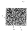
- FIG. 2 shows the structure produced of the alloy powder according to the invention
- alloy powder contains in addition to the Base element aluminum has a very high silicon content of approx. 62% by weight as well approx. 20% by weight titanium.
- a Metal alloy with the appropriate composition processed into powder if necessary, it can also be advantageous to mix different alloy powders Mix composition so that an alloy powder with the desired Composition arises.
- Al-Ti phases form in the basic matrix.
- the formation of high-melting Al-Ti phases such as Al 3 Ti, whose melting point is approximately 1,340 ° C., is particularly preferred.
- Silicon particles 22 are embedded in this very robust basic matrix 20, wherein the alloying element titanium continues to cause grain refinement when they are separated from the melt.
- the micrograph shown in FIG. 2 shows this basic matrix 20 with embedded silicon particles 22, the silicon particles 22 being finely dispersed in a size of only approximately 20 ⁇ m, in particular of 1 to 5 ⁇ m, in spite of the high silicon content of approximately 60% by weight.
- the Si content can be increased significantly without the Si primary crystals forming from the melt becoming too large and rod-like / lamella-like.
- the Control macro hardness - for example up to over 550 HV with AlSi50Ti30 - whereby nevertheless, an increased tendency to crack formation is avoided.
- the addition of small amounts of nod (Ni) in the range from 1 to 15% has an advantageous effect.
- Further wear resistance of the microstructure matrix can also be achieved by adding hard material particles.
- SiC and / or B 4 C can be stored up to 30%, in particular 5 to 20%, by weight as a wear protection carrier.
- B 4 C In conjunction with a fuel such as gas or hydrogen or in high-performance engines, B 4 C also takes on the role of a solid lubricant due to its oxidation to B 2 O 3 .
- the coating takes place - as shown in Fig. 3 - by means of a coating lance 32, which has a feed 37 for the alloy powder and a light guide 33 for coupling a laser beam.
- a diode laser is used as the laser or a solid-state laser such as Nd: YAG laser with an output of approx. 3 kW used.
- the alloy powder is fed through the feed 37 of a nozzle 38 supplied, from which a powder jet 36 emerges; from the light guide 33 emerging laser beam is by means of several optical elements - schematically and exemplarily indicated with 34a, 34b - focused.
- the Coating lance 32 is rotatable and / or displaceable relative to component 30, so that a targeted coating of the component 30 in regions is possible; if necessary the focus of the laser beam 35 and / or the nozzle 38 adjustable.
- the alloy powder emerging from the nozzle 38 is sprayed in the direction of the component to be coated, it being at least partially melted by the heat of the laser beam.
- the powder jet 36 is guided in the vicinity of or through the laser beam 35.
- the powder jet emerges from the nozzle 38 in such a way that the required area is acted upon by the desired amount of alloy powder when it strikes the component surface 31a of the component 30 to be coated.
- the focus 35a of the laser beam 35 is adjusted so that it lies exactly on the component surface; if the heating is too strong here, it can also be advantageous to guide the coating lance 32 in such a way that the component surface comes to lie above or below the focus 35a.
- the energy density in the focal spot of the laser steel is approximately 10 4 W / cm 2 .
- alloying takes place in the 1/10 mm area combined with an application of a few millimeters, approx. 2-3 mm, thick layer; that shown and described with Figure 2 In this way, the wear protection layer is firmly anchored in the base material.
- the component - the cylinder head - expediently cooled This is a compromise between a quick Heat dissipation to prevent the melting of the Base material, between an ideal gradient to form the desired structure and between a slow cooling and slight Temperature differences to avoid cracks found.
- the whole is done Coating process under a protective gas atmosphere such as argon or nitrogen.
- a protective gas atmosphere such as argon or nitrogen.
- the powder material is sprayed with protective gas, whereby the Shielding gas carried in the feed 37 or in a separate line to the Area of the nozzle 38 is passed.
- alloy powder As an alternative to applying the alloy powder as described, this can be done Alloy powder also in the form of a paste for example coating area are applied.
- the coating lance then includes only the laser device and possibly a protective gas supply device, which makes it structurally much simpler.
- the cylinder head blank provided for coating is combined with a a certain allowance, so that subsequently possibly in the coating occurring heat distortion in the finishing can be compensated.
- the valve seat areas to be coated are pre-processed with a certain undersize, since a layer is applied there. During the Coating of the valve seat area 31a, 31b, 31c, 31d moves the Coating lance 32 with a linear speed of up to 3 m / min and will rotated accordingly. There are several adjacent caterpillars - each after width one to two - with a degree of overlap of approx. 30-50% applied. Finally, the coated area is machined.
Landscapes
- Chemical & Material Sciences (AREA)
- Engineering & Computer Science (AREA)
- Materials Engineering (AREA)
- Mechanical Engineering (AREA)
- Metallurgy (AREA)
- Organic Chemistry (AREA)
- Chemical Kinetics & Catalysis (AREA)
- Coating By Spraying Or Casting (AREA)
- Other Surface Treatments For Metallic Materials (AREA)
Abstract
Description
- Fig. 1
- ein Schliffbild eines Gefüges mit hohem Si-Anteil unter Verwendung eines herkömmlichen Legierungspulvers,
- Fig. 2
- ein Schliffbild eines Gefüges mit hohem Si-Anteil unter Verwendung des erfindungsgemäßen Legierungspulvers sowie
- Fig. 3
- schematisch und beispielhaft die Aufbringung des Legierungspulvers auf den Ventilsitzbereich eines Zylinderkopfes.
Claims (11)
- Legierungungspulver zur Beschichtung eines insbesondere aus einer Aluminium-Legierung bestehenden Bauteiles, insbesondere des Ventilsitzbereiches eines Zylinderkopfes einer Brennkraftmaschine, dadurch gekennzeichnet, dass als wesentliche Bestandteile Aluminium (Al), Silizium (Si) und Titan (Ti) enthalten sind.
- Legierungspulver nach Anspruch 1, dadurch gekennzeichnet, dass neben dem Basiselement Aluminium (Al) 10-70 gew.-%, insbesondere 20-50 gew.-% Silizium (Si) sowie 5-50 gew.-%, insbesondere 10-40 gew.-% Titan (Ti) enthalten sind.
- Legierungspulver nach Anspruch 1 oder 2, dadurch gekennzeichnet, dass bis zu 25 gew.-%, insbesondere 1-15 gew.-% Nickel (Ni) und/oder bis zu 20 gew.-%, insbesondere 1-10 gew.-% Kupfer (Cu) enthalten sind.
- Legierungspulver nach einem der vorhergehenden Ansprüche, dadurch gekennzeichnet, dass ein Hochtemperaturschmierstoff enthalten ist.
- Legierungspulver nach Anspruch 4, dadurch gekennzeichnet, dass Bornitrit (BN), Graphit, B2O3 und/oder Co/Cr2O2 gewichtsanteilig mit zusammen bis zu 20 %, insbesondere mit 5-10 % enthalten sind.
- Legierungspulver nach einem der vorhergehenden Ansprüche, dadurch gekennzeichnet, dass Hartstoffpartikel enthalten sind.
- Legierungspulver nach Anspruch 6, dadurch gekennzeichnet, dass SiC und/oder B4C gewichtsanteilig mit zusammen bis zu 30 %, insbesondere 5-20 % enthalten sind.
- Verfahren zur Beschichtung eines insbesondere aus einer Aluminium-Legierung bestehenden Bauteiles, insbesondere des Ventilsitzbereiches (31a, 31b, 31c, 31d) eines Zylinderkopfes (30) einer Brennkraftmaschine unter Verwendung eines Legierungspulvers nach einem der vorhergehenden Ansprüche mittels eines Hochenergiestrahls, insbesondere eines Laserstrahls (35), wobei das Legierungspulver (36) zumindest teilweise von der festen in die schmelzflüssige Phase umgewandelt und in einem Schmelzbad auf die Bauteiloberfläche auf-/eingebracht wird, worauf sich beim folgenden Erstarrungsprozess in der Gefügegrundmatrix eine hochschmelzende intermetallische Al-Ti Phase (20) mit eingelagerten Si-Partikeln (22) ausbildet.
- Verfahren nach Anspruch 8, dadurch gekennzeichnet, dass das Legierungspulver mittels einer geeigneten eine Düse (38) umfassenden Pulverfördereinrichtung, welche mit dem Laserstrahl (35) zusammenwirkt, auf die Bauteiloberfläche aufgebracht wird, indem das Pulver im Laserstrahl (35) oder zumindest in dessen Nähe wenigstens teilweise aufgeschmolzen wird.
- Verfahren nach einem der Ansprüche 8 und 9, dadurch gekennzeichnet, dass das Bauteil (30) während des Beschichtens gekühlt wird.
- Verfahren nach einem der Ansprüche 8 und 9, dadurch gekennzeichnet, dass die Beschichtung unter Schutzgasatmosphäre erfolgt.
Applications Claiming Priority (2)
| Application Number | Priority Date | Filing Date | Title |
|---|---|---|---|
| DE10151716 | 2001-10-19 | ||
| DE10151716A DE10151716A1 (de) | 2001-10-19 | 2001-10-19 | Legierungspulver zur Beschichtung insbesondere des Ventilsitzbereiches eines Zylinderkopfes einer Brennkraftmaschine sowie Beschichtungsverfahren |
Publications (2)
| Publication Number | Publication Date |
|---|---|
| EP1304396A1 true EP1304396A1 (de) | 2003-04-23 |
| EP1304396B1 EP1304396B1 (de) | 2005-04-06 |
Family
ID=7703089
Family Applications (1)
| Application Number | Title | Priority Date | Filing Date |
|---|---|---|---|
| EP02019625A Expired - Lifetime EP1304396B1 (de) | 2001-10-19 | 2002-09-03 | Beschichtungsverfahren |
Country Status (2)
| Country | Link |
|---|---|
| EP (1) | EP1304396B1 (de) |
| DE (2) | DE10151716A1 (de) |
Cited By (8)
| Publication number | Priority date | Publication date | Assignee | Title |
|---|---|---|---|---|
| CN103302285A (zh) * | 2013-06-18 | 2013-09-18 | 江苏和昊激光科技有限公司 | 专用于冲头表面激光熔覆的镍基金属陶瓷合金粉末 |
| CN104018892A (zh) * | 2014-05-28 | 2014-09-03 | 中广核核电运营有限公司 | 汽轮机高压汽阀阀盖密封面凹坑的修复方法 |
| CN106367752A (zh) * | 2013-06-28 | 2017-02-01 | 蒋红娟 | 镀层厚度易控制的铜合金表面的激光熔覆工艺 |
| CN106757013A (zh) * | 2017-01-20 | 2017-05-31 | 青岛滨海学院 | 一种钛合金激光表面硅化物增强多元高温合金化层及其制备方法 |
| CN109763125A (zh) * | 2019-01-18 | 2019-05-17 | 青岛滨海学院 | 一种耐高温磨损的高熵合金涂层及其制备工艺、应用 |
| CN110373668A (zh) * | 2019-07-31 | 2019-10-25 | 江西科技学院 | 一种铝合金复合材料及其制备方法 |
| WO2020254371A1 (fr) * | 2019-06-19 | 2020-12-24 | Renault S.A.S | Dispositif de depot d'un revetement pour la fabrication d'un siege de soupape |
| CN112522546A (zh) * | 2020-10-26 | 2021-03-19 | 中北大学 | 一种利用slm技术制备b4c增强铝基复合材料的方法 |
Families Citing this family (2)
| Publication number | Priority date | Publication date | Assignee | Title |
|---|---|---|---|---|
| NL2001869C2 (nl) * | 2008-08-01 | 2010-02-02 | Stichting Materials Innovation | Cilinderkop met klepzitting alsmede werkwijze voor het vervaardigen daarvan. |
| DE102017218580A1 (de) | 2017-10-18 | 2019-04-18 | Christian Maier GmbH & Co. KG | Verfahren zum Aufbringen einer Schicht auf ein Bauteil und Bauteil hergestellt nach dem Verfahren |
Citations (3)
| Publication number | Priority date | Publication date | Assignee | Title |
|---|---|---|---|---|
| JPH04235246A (ja) * | 1990-12-28 | 1992-08-24 | Nippon Cement Co Ltd | セラミックスのメタライズ用合金及びメタライズ方法 |
| JPH0565572A (ja) * | 1991-09-10 | 1993-03-19 | Honda Motor Co Ltd | 高温耐酸化性構造部材 |
| US5833772A (en) * | 1992-11-18 | 1998-11-10 | Elkem Asa | Silicon alloy, method for producing the alloy and method for production of consolidated products from silicon |
Family Cites Families (5)
| Publication number | Priority date | Publication date | Assignee | Title |
|---|---|---|---|---|
| US5545487A (en) * | 1994-02-12 | 1996-08-13 | Hitachi Powdered Metals Co., Ltd. | Wear-resistant sintered aluminum alloy and method for producing the same |
| DE4443147A1 (de) * | 1994-12-05 | 1996-06-27 | Dechema | Korrosionsbeständiger Werkstoff für Hochtemperaturanwendungen in sulfidierenden Prozeßgasen |
| DE19802298C2 (de) * | 1998-01-22 | 2000-11-23 | Daimler Chrysler Ag | Verfahren zur Erzielung funktioneller Metall-, Keramik- oder Keramik/Metall-Schichten auf der Innenwand von Hohlkörpern |
| DE19941562A1 (de) * | 1999-02-19 | 2000-08-31 | Volkswagen Ag | Verfahren und Anordnung zum Herstellen verschleißfester Oberflächen |
| DE10009133A1 (de) * | 2000-02-26 | 2001-08-30 | Volkswagen Ag | Verfahren zum Laserbeschichten einer Oberfläche |
-
2001
- 2001-10-19 DE DE10151716A patent/DE10151716A1/de not_active Ceased
-
2002
- 2002-09-03 DE DE50202698T patent/DE50202698D1/de not_active Expired - Lifetime
- 2002-09-03 EP EP02019625A patent/EP1304396B1/de not_active Expired - Lifetime
Patent Citations (3)
| Publication number | Priority date | Publication date | Assignee | Title |
|---|---|---|---|---|
| JPH04235246A (ja) * | 1990-12-28 | 1992-08-24 | Nippon Cement Co Ltd | セラミックスのメタライズ用合金及びメタライズ方法 |
| JPH0565572A (ja) * | 1991-09-10 | 1993-03-19 | Honda Motor Co Ltd | 高温耐酸化性構造部材 |
| US5833772A (en) * | 1992-11-18 | 1998-11-10 | Elkem Asa | Silicon alloy, method for producing the alloy and method for production of consolidated products from silicon |
Non-Patent Citations (2)
| Title |
|---|
| PATENT ABSTRACTS OF JAPAN vol. 016, no. 584 (C - 1013) 24 December 1992 (1992-12-24) * |
| PATENT ABSTRACTS OF JAPAN vol. 017, no. 382 (C - 1085) 19 July 1993 (1993-07-19) * |
Cited By (12)
| Publication number | Priority date | Publication date | Assignee | Title |
|---|---|---|---|---|
| CN103302285A (zh) * | 2013-06-18 | 2013-09-18 | 江苏和昊激光科技有限公司 | 专用于冲头表面激光熔覆的镍基金属陶瓷合金粉末 |
| CN103302285B (zh) * | 2013-06-18 | 2015-05-20 | 江苏和昊激光科技有限公司 | 专用于冲头表面激光熔覆的镍基金属陶瓷合金粉末 |
| CN106367752A (zh) * | 2013-06-28 | 2017-02-01 | 蒋红娟 | 镀层厚度易控制的铜合金表面的激光熔覆工艺 |
| CN104018892A (zh) * | 2014-05-28 | 2014-09-03 | 中广核核电运营有限公司 | 汽轮机高压汽阀阀盖密封面凹坑的修复方法 |
| CN104018892B (zh) * | 2014-05-28 | 2015-10-28 | 中广核核电运营有限公司 | 汽轮机高压汽阀阀盖密封面凹坑的修复方法 |
| CN106757013A (zh) * | 2017-01-20 | 2017-05-31 | 青岛滨海学院 | 一种钛合金激光表面硅化物增强多元高温合金化层及其制备方法 |
| CN109763125A (zh) * | 2019-01-18 | 2019-05-17 | 青岛滨海学院 | 一种耐高温磨损的高熵合金涂层及其制备工艺、应用 |
| WO2020254371A1 (fr) * | 2019-06-19 | 2020-12-24 | Renault S.A.S | Dispositif de depot d'un revetement pour la fabrication d'un siege de soupape |
| FR3097561A1 (fr) * | 2019-06-19 | 2020-12-25 | Renault S.A.S | Dispositif de dépôt d'un revêtement pour la fabrication d'un siège de soupape |
| CN110373668A (zh) * | 2019-07-31 | 2019-10-25 | 江西科技学院 | 一种铝合金复合材料及其制备方法 |
| CN112522546A (zh) * | 2020-10-26 | 2021-03-19 | 中北大学 | 一种利用slm技术制备b4c增强铝基复合材料的方法 |
| CN112522546B (zh) * | 2020-10-26 | 2022-02-08 | 中北大学 | 一种利用slm技术制备b4c增强铝基复合材料的方法 |
Also Published As
| Publication number | Publication date |
|---|---|
| DE10151716A1 (de) | 2003-05-08 |
| DE50202698D1 (de) | 2005-05-12 |
| EP1304396B1 (de) | 2005-04-06 |
Similar Documents
| Publication | Publication Date | Title |
|---|---|---|
| EP1322794B1 (de) | Thermisch aufgetragene beschichtung für kolbenringe aus mechanisch legierten pulvern | |
| DE69229821T2 (de) | Aufschweisslegierungen auf Chrom-Basis | |
| DE102007019510B3 (de) | Zu einer Gleitpaarung gehörendes Maschinenteil sowie Verfahren zu dessen Herstellung | |
| DE3813802C2 (de) | ||
| EP0622476B1 (de) | Metallsubstrate mit laserinduzierter MMC-Beschichtung | |
| DE2926879A1 (de) | Verfahren zum beschichten der oberflaeche von metallsubstraten mit verschleissfesten materialien | |
| DE3506302C2 (de) | ||
| EP1124660B1 (de) | Zylinderkurbelgehäuse, verfahren zur herstellung der zylinderlaufbuchsen dafür und verfahren zur herstellung des zylinderkurbelgehäuses mit diesen zylinderlaufbuchsen | |
| DE3922378A1 (de) | Verfahren zum herstellung verschleissfester oberflaechen an bauteilen aus einer aluminium-silicium-legierung | |
| DE102016114549B4 (de) | Abriebfeste kupfer-basierte legierung, plattierschicht, und ventilsystemelement und gleitelement für eine verbrennungsmaschine | |
| DE1521369B2 (de) | Pulverfoermige, selbstfliessende flammspritzmasse | |
| DE102012211440A1 (de) | Kolben | |
| DE102005008569A1 (de) | Reibelement und Verfahren zu dessen Herstellung | |
| DE102012013020B3 (de) | Verfahren zum Beschichten eines Substrats mit einem Spritzwerkstoff und damit erzeugbare Funktionsschicht | |
| EP1304396B1 (de) | Beschichtungsverfahren | |
| EP0837152B1 (de) | Verfahren zum Beschichten eines aus einer Aluminium-Legierung bestehenden Bauteils einer Brennkraftmaschine mit Silicium | |
| EP1565646A1 (de) | Ventilsitz und verfahren zur herstellung eines ventilsitzes | |
| DE102006055994A1 (de) | Verfahren zum Aufbringen einer Beschichtung auf ein Bauteil sowie Bauteil | |
| DE102017218592B4 (de) | Verfahren zur Herstellung eines Gleitlagers sowie ein mit dem Verfahren hergestelltes Gleitlager | |
| DE10124250C2 (de) | Verfahren zur Bildung einer hochfesten und verschleißbeständigen Verbundschicht | |
| DE102010049840B4 (de) | Bauteil mit einer Verschleißschutzschicht | |
| DE102011120989B3 (de) | Spritzwerkstoff für thermische Spritzbeschichtungen,dessen Verwendung und mit dem Spritzwerkstoffthermisch beschichteter Grauguss-Grundkörper | |
| DE10059903B4 (de) | Kolben mit Verschleißschutzschicht | |
| EP1173689B1 (de) | Oberflächenlegiertes zylindrisches, teilzylindrisches oder hohlzylindrisches bauteil | |
| DE10163970B4 (de) | Verschleißarme Werkstückfläche und Verfahren zu ihrer Herstellung |
Legal Events
| Date | Code | Title | Description |
|---|---|---|---|
| PUAI | Public reference made under article 153(3) epc to a published international application that has entered the european phase |
Free format text: ORIGINAL CODE: 0009012 |
|
| AK | Designated contracting states |
Designated state(s): AT BE BG CH CY CZ DE DK EE ES FI FR GB GR IE IT LI LU MC NL PT SE SK TR |
|
| AX | Request for extension of the european patent |
Extension state: AL LT LV MK RO SI |
|
| 17P | Request for examination filed |
Effective date: 20030506 |
|
| AKX | Designation fees paid |
Designated state(s): DE FR GB IT |
|
| 17Q | First examination report despatched |
Effective date: 20040326 |
|
| GRAP | Despatch of communication of intention to grant a patent |
Free format text: ORIGINAL CODE: EPIDOSNIGR1 |
|
| RTI1 | Title (correction) |
Free format text: COATING PROCESS |
|
| GRAS | Grant fee paid |
Free format text: ORIGINAL CODE: EPIDOSNIGR3 |
|
| GRAA | (expected) grant |
Free format text: ORIGINAL CODE: 0009210 |
|
| AK | Designated contracting states |
Kind code of ref document: B1 Designated state(s): DE FR GB IT |
|
| REG | Reference to a national code |
Ref country code: GB Ref legal event code: FG4D Free format text: NOT ENGLISH |
|
| GBT | Gb: translation of ep patent filed (gb section 77(6)(a)/1977) |
Effective date: 20050406 |
|
| REF | Corresponds to: |
Ref document number: 50202698 Country of ref document: DE Date of ref document: 20050512 Kind code of ref document: P |
|
| ET | Fr: translation filed | ||
| PLBE | No opposition filed within time limit |
Free format text: ORIGINAL CODE: 0009261 |
|
| STAA | Information on the status of an ep patent application or granted ep patent |
Free format text: STATUS: NO OPPOSITION FILED WITHIN TIME LIMIT |
|
| 26N | No opposition filed |
Effective date: 20060110 |
|
| PGFP | Annual fee paid to national office [announced via postgrant information from national office to epo] |
Ref country code: DE Payment date: 20140919 Year of fee payment: 13 |
|
| PGFP | Annual fee paid to national office [announced via postgrant information from national office to epo] |
Ref country code: GB Payment date: 20140926 Year of fee payment: 13 |
|
| PGFP | Annual fee paid to national office [announced via postgrant information from national office to epo] |
Ref country code: IT Payment date: 20140924 Year of fee payment: 13 |
|
| PGFP | Annual fee paid to national office [announced via postgrant information from national office to epo] |
Ref country code: FR Payment date: 20140929 Year of fee payment: 13 |
|
| REG | Reference to a national code |
Ref country code: DE Ref legal event code: R119 Ref document number: 50202698 Country of ref document: DE |
|
| PG25 | Lapsed in a contracting state [announced via postgrant information from national office to epo] |
Ref country code: IT Free format text: LAPSE BECAUSE OF NON-PAYMENT OF DUE FEES Effective date: 20150903 |
|
| GBPC | Gb: european patent ceased through non-payment of renewal fee |
Effective date: 20150903 |
|
| REG | Reference to a national code |
Ref country code: FR Ref legal event code: ST Effective date: 20160531 |
|
| PG25 | Lapsed in a contracting state [announced via postgrant information from national office to epo] |
Ref country code: DE Free format text: LAPSE BECAUSE OF NON-PAYMENT OF DUE FEES Effective date: 20160401 Ref country code: GB Free format text: LAPSE BECAUSE OF NON-PAYMENT OF DUE FEES Effective date: 20150903 |
|
| PG25 | Lapsed in a contracting state [announced via postgrant information from national office to epo] |
Ref country code: FR Free format text: LAPSE BECAUSE OF NON-PAYMENT OF DUE FEES Effective date: 20150930 |