EP1303387B1 - Verfahren zur herstellung von strukturen durch gebrauch von zentrifugalen kräften - Google Patents
Verfahren zur herstellung von strukturen durch gebrauch von zentrifugalen kräften Download PDFInfo
- Publication number
- EP1303387B1 EP1303387B1 EP01931299A EP01931299A EP1303387B1 EP 1303387 B1 EP1303387 B1 EP 1303387B1 EP 01931299 A EP01931299 A EP 01931299A EP 01931299 A EP01931299 A EP 01931299A EP 1303387 B1 EP1303387 B1 EP 1303387B1
- Authority
- EP
- European Patent Office
- Prior art keywords
- mold
- poly
- process according
- derivatives
- phase
- Prior art date
- Legal status (The legal status is an assumption and is not a legal conclusion. Google has not performed a legal analysis and makes no representation as to the accuracy of the status listed.)
- Expired - Lifetime
Links
Images


Classifications
-
- A—HUMAN NECESSITIES
- A61—MEDICAL OR VETERINARY SCIENCE; HYGIENE
- A61K—PREPARATIONS FOR MEDICAL, DENTAL OR TOILETRY PURPOSES
- A61K9/00—Medicinal preparations characterised by special physical form
- A61K9/0087—Galenical forms not covered by A61K9/02 - A61K9/7023
- A61K9/0092—Hollow drug-filled fibres, tubes of the core-shell type, coated fibres, coated rods, microtubules or nanotubes
-
- B—PERFORMING OPERATIONS; TRANSPORTING
- B29—WORKING OF PLASTICS; WORKING OF SUBSTANCES IN A PLASTIC STATE IN GENERAL
- B29C—SHAPING OR JOINING OF PLASTICS; SHAPING OF MATERIAL IN A PLASTIC STATE, NOT OTHERWISE PROVIDED FOR; AFTER-TREATMENT OF THE SHAPED PRODUCTS, e.g. REPAIRING
- B29C39/00—Shaping by casting, i.e. introducing the moulding material into a mould or between confining surfaces without significant moulding pressure; Apparatus therefor
- B29C39/003—Shaping by casting, i.e. introducing the moulding material into a mould or between confining surfaces without significant moulding pressure; Apparatus therefor characterised by the choice of material
- B29C39/006—Monomers or prepolymers
-
- B—PERFORMING OPERATIONS; TRANSPORTING
- B29—WORKING OF PLASTICS; WORKING OF SUBSTANCES IN A PLASTIC STATE IN GENERAL
- B29C—SHAPING OR JOINING OF PLASTICS; SHAPING OF MATERIAL IN A PLASTIC STATE, NOT OTHERWISE PROVIDED FOR; AFTER-TREATMENT OF THE SHAPED PRODUCTS, e.g. REPAIRING
- B29C39/00—Shaping by casting, i.e. introducing the moulding material into a mould or between confining surfaces without significant moulding pressure; Apparatus therefor
- B29C39/02—Shaping by casting, i.e. introducing the moulding material into a mould or between confining surfaces without significant moulding pressure; Apparatus therefor for making articles of definite length, i.e. discrete articles
- B29C39/04—Shaping by casting, i.e. introducing the moulding material into a mould or between confining surfaces without significant moulding pressure; Apparatus therefor for making articles of definite length, i.e. discrete articles using movable moulds not applied
- B29C39/08—Introducing the material into the mould by centrifugal force
-
- B—PERFORMING OPERATIONS; TRANSPORTING
- B29—WORKING OF PLASTICS; WORKING OF SUBSTANCES IN A PLASTIC STATE IN GENERAL
- B29C—SHAPING OR JOINING OF PLASTICS; SHAPING OF MATERIAL IN A PLASTIC STATE, NOT OTHERWISE PROVIDED FOR; AFTER-TREATMENT OF THE SHAPED PRODUCTS, e.g. REPAIRING
- B29C41/00—Shaping by coating a mould, core or other substrate, i.e. by depositing material and stripping-off the shaped article; Apparatus therefor
- B29C41/02—Shaping by coating a mould, core or other substrate, i.e. by depositing material and stripping-off the shaped article; Apparatus therefor for making articles of definite length, i.e. discrete articles
- B29C41/04—Rotational or centrifugal casting, i.e. coating the inside of a mould by rotating the mould
- B29C41/042—Rotational or centrifugal casting, i.e. coating the inside of a mould by rotating the mould by rotating a mould around its axis of symmetry
-
- B—PERFORMING OPERATIONS; TRANSPORTING
- B29—WORKING OF PLASTICS; WORKING OF SUBSTANCES IN A PLASTIC STATE IN GENERAL
- B29C—SHAPING OR JOINING OF PLASTICS; SHAPING OF MATERIAL IN A PLASTIC STATE, NOT OTHERWISE PROVIDED FOR; AFTER-TREATMENT OF THE SHAPED PRODUCTS, e.g. REPAIRING
- B29C41/00—Shaping by coating a mould, core or other substrate, i.e. by depositing material and stripping-off the shaped article; Apparatus therefor
- B29C41/34—Component parts, details or accessories; Auxiliary operations
- B29C41/50—Shaping under special conditions, e.g. vacuum
-
- A—HUMAN NECESSITIES
- A61—MEDICAL OR VETERINARY SCIENCE; HYGIENE
- A61B—DIAGNOSIS; SURGERY; IDENTIFICATION
- A61B17/00—Surgical instruments, devices or methods, e.g. tourniquets
- A61B17/11—Surgical instruments, devices or methods, e.g. tourniquets for performing anastomosis; Buttons for anastomosis
- A61B17/1128—Surgical instruments, devices or methods, e.g. tourniquets for performing anastomosis; Buttons for anastomosis of nerves
-
- B—PERFORMING OPERATIONS; TRANSPORTING
- B29—WORKING OF PLASTICS; WORKING OF SUBSTANCES IN A PLASTIC STATE IN GENERAL
- B29C—SHAPING OR JOINING OF PLASTICS; SHAPING OF MATERIAL IN A PLASTIC STATE, NOT OTHERWISE PROVIDED FOR; AFTER-TREATMENT OF THE SHAPED PRODUCTS, e.g. REPAIRING
- B29C37/00—Component parts, details, accessories or auxiliary operations, not covered by group B29C33/00 or B29C35/00
- B29C37/006—Degassing moulding material or draining off gas during moulding
-
- B—PERFORMING OPERATIONS; TRANSPORTING
- B29—WORKING OF PLASTICS; WORKING OF SUBSTANCES IN A PLASTIC STATE IN GENERAL
- B29K—INDEXING SCHEME ASSOCIATED WITH SUBCLASSES B29B, B29C OR B29D, RELATING TO MOULDING MATERIALS OR TO MATERIALS FOR MOULDS, REINFORCEMENTS, FILLERS OR PREFORMED PARTS, e.g. INSERTS
- B29K2105/00—Condition, form or state of moulded material or of the material to be shaped
- B29K2105/0005—Condition, form or state of moulded material or of the material to be shaped containing compounding ingredients
- B29K2105/0014—Catalysts
-
- B—PERFORMING OPERATIONS; TRANSPORTING
- B29—WORKING OF PLASTICS; WORKING OF SUBSTANCES IN A PLASTIC STATE IN GENERAL
- B29K—INDEXING SCHEME ASSOCIATED WITH SUBCLASSES B29B, B29C OR B29D, RELATING TO MOULDING MATERIALS OR TO MATERIALS FOR MOULDS, REINFORCEMENTS, FILLERS OR PREFORMED PARTS, e.g. INSERTS
- B29K2105/00—Condition, form or state of moulded material or of the material to be shaped
- B29K2105/04—Condition, form or state of moulded material or of the material to be shaped cellular or porous
-
- B—PERFORMING OPERATIONS; TRANSPORTING
- B29—WORKING OF PLASTICS; WORKING OF SUBSTANCES IN A PLASTIC STATE IN GENERAL
- B29L—INDEXING SCHEME ASSOCIATED WITH SUBCLASS B29C, RELATING TO PARTICULAR ARTICLES
- B29L2023/00—Tubular articles
-
- B—PERFORMING OPERATIONS; TRANSPORTING
- B29—WORKING OF PLASTICS; WORKING OF SUBSTANCES IN A PLASTIC STATE IN GENERAL
- B29L—INDEXING SCHEME ASSOCIATED WITH SUBCLASS B29C, RELATING TO PARTICULAR ARTICLES
- B29L2031/00—Other particular articles
- B29L2031/753—Medical equipment; Accessories therefor
-
- Y—GENERAL TAGGING OF NEW TECHNOLOGICAL DEVELOPMENTS; GENERAL TAGGING OF CROSS-SECTIONAL TECHNOLOGIES SPANNING OVER SEVERAL SECTIONS OF THE IPC; TECHNICAL SUBJECTS COVERED BY FORMER USPC CROSS-REFERENCE ART COLLECTIONS [XRACs] AND DIGESTS
- Y10—TECHNICAL SUBJECTS COVERED BY FORMER USPC
- Y10T—TECHNICAL SUBJECTS COVERED BY FORMER US CLASSIFICATION
- Y10T428/00—Stock material or miscellaneous articles
- Y10T428/13—Hollow or container type article [e.g., tube, vase, etc.]
- Y10T428/1352—Polymer or resin containing [i.e., natural or synthetic]
- Y10T428/139—Open-ended, self-supporting conduit, cylinder, or tube-type article
Definitions
- This invention relates to a process of producing a product, in particular to a process of manufacturing structures and particularly polymeric tubular structures with complex and unique morphologies in the walls, and on the inner and outer surfaces of the structures.
- Tubular structures have been prepared by a number of techniques, each of which has limitations for each application.
- a limitation is the abundant material required to prepare structures of limited size and shape, which can prove costly.
- porous polymeric tubes also known as hollow fiber membranes (HFMs)
- HFMs hollow fiber membranes
- the invention comprises a process to prepare HFMs, or any hollow structure, with a broad range of wall and surface morphologies, dimensions and shapes. Such wall morphologies allow HFMs to be manufactured with considerably different transport properties while maintaining similar mechanical properties.
- HFMs are commonly prepared by phase inversion through an annular die (or spinneret) where the solvent/non-solvent system controls many of the resulting properties, such as morphology of the wall structure.
- the dimensions are controlled by the spinneret, which must be finely tuned for concentricity. While the spinning technique has a proven record commercially, it requires abundant material and requires a certain amount of art to prepare reproducible HFMs.
- Centrifugal casting is a process used to make a wide number of structures, both tubular and non-concentric (United States Patent Nos. 5,266,325; 5,292,515).
- a cylindrical mold is partially filled with a monomer, polymer melt, or monomer solution, and with air present inside the mold, coats the periphery of the mold under centrifugal action.
- the material spun to the outer portion of the mold is then held in place using temperature changes (cooling), polymerization or evaporation of the solvent
- two phases are present inside the mold (air and liquid) before rotation; phase separation is not necessary for tubular formation.
- Wall morphologies are only attained by the addition of a porogen (salt, ethylene glycol etc.) that is leached out post-polymerization. Since air is required in the mold to form a tube (compared to a rod), attaining small diameter tubes with a small inner diameter on the micron scale cannot be achieved. Surface tension between the liquid and the gas inside the mold prevents miniaturization of the inner diameters for tens of centimeter length tubes.
- a porogen salt, ethylene glycol etc.
- tubes are formed around a mandrel that is sequentially dipped in a polymer solution and non-solvent system, thereby coating the mandrel with the polymer via a phase inversion process.
- the mandrel may be dipped in a polymer solution and the solvent left to evaporate.
- Patent Abstracts of Japan, vol. 018, no. 557 (P-1817). 24 October 1994 & JP 06 202087 A (Sumitomo Electric Ind Ltd) is directed to a method for producing a composite film of uniform transmittance.
- the method includes dissolving a high-polymer material and a liquid crystal material in a low boiling solvent to prepare a coating liquid, which is then applied on a substrate.
- the coated substrate is placed in a gaseous flow of gaseous nitrogen, or is rotated to evaporate the solvent.
- the coated surface is smoothed by the wind force of the gaseous flow or the centrifugal force generated by rotation, thereby producing a structure wherein the polymer and liquid crystal materials are finely separated in phase.
- U.S. Patent No. 5,250,240 to Kim et al. teaches an economically way of producing a hollow, fibrous, porous separation membrane from polyolefins by thermally induced phase separation.
- the process comprises spinning a melt blend solution of a polyolefin of a certain melt index in a diluent selected from the group consisting of natural soybean oil, pure linoleic acid, and a mixture of oleic acid, linoleic acid and palmitic acid to form a hollow, fibrous, porous, polyolefin separation membrane; extracting out the diluent followed by coagulating the membrane with a coagulating and extracting solvent; and evaporating out the solvent together with any residue of the diluent.
- a diluent selected from the group consisting of natural soybean oil, pure linoleic acid, and a mixture of oleic acid, linoleic acid and palmitic acid
- Patent Abstracts of Japan, vol. 013, no. 589 (C-670), 25 December 1989 & JP 01 247435 discloses a method of producing a porous objection without using any solvent
- the method includes heat-treating an intimate mixture of a linear aromatic polyether sulfone and poly(2-oxazoline) to a specified temperature range to effect phase separation of these two polymers in the state of continuous phases.
- the mixture is then cooled to the glass transition temperature or below, and the poly(2-oxazoline) is extracted with water to produce a porous object.
- UK Patent Application, GB 2 003 108 A (Sandoz Ltd) is directed to a method for producing microspheres of a core material and a polymer by using a low temperature phase separation step.
- the method comprises adding a phase separation agent to a medium comprising a solution of the polymer and a solution or dispersion of the core material at a temperature of -40 °C to -100 °C.
- This patent application teaches that the low temperature phase separation step prevents uncontrolled agglomeration of the microspheres.
- a rotational structure such as a magnetic circular disc suitable as pulse transmitters for digital angular step resolvers.
- the rotational structure is produced by filling a rotational mold with a mixture of casting resin and a comminuted magnetizable filler material, and heating the mixture in the mold to maintain its fluidity while centrifuging until the filler material is driven to the peripheral marginal zone where it becomes uniformly distributed along the periphery. Thereafter, the mixture is hardened by permitting it to cool down to normal room temperature.
- This object of the present invention can be achieved by the process of producing a product comprising
- the product formed by this process may be removed from the mold, or alternatively remain in the mold where the product and the mold are used for various applications.
- the product may be a polymeric material, in which case the solution includes either monomers or polymers or both.
- the product may have a wall morphology that includes a porous structure, a gel structure or overlapping regions of porous/gel structure.
- the polymeric product may have a wall morphology that includes a predominantly gel morphology with porous channels running from a periphery to a lumenal side, resulting in spotting on an outer wall surface.
- the polymeric product may be a multi-layered product produced by repeating steps a), b) and c), at least once to produce a multi-layered product.
- the polymeric product may be used as a reservoir for the delivery of drugs, therapeutics, cells, cell products, genes, viral vectors, proteins, peptides, hormones, carbohydrates, growth factors.
- the polymeric product may contain microspheres containing preselected constituents, and wherein the product includes said microspheres distributed either uniformly or in a gradient within the wall structure of the product.
- the forces that generate the tubular structures in this novel process are inertial forces associated with spinning a mold.
- a mold is filled with a homogeneous solution containing at least two components that can be phase separated thereby displacing substantially all of the visible air inside the mold.
- the mold is then rotated at some pre-determined speed, for example by being inserted into a rotating device, such as a drill chuck, or lathe. Phase separation of this homogeneous solution is induced by a phase separating agent while the mold is spinning.
- this phase which adopts the shape of the inner surface of the mold needs to be stabilized to produce the product.
- this separated phase must be stabilized to prevent it from falling off the surface of the mold and returning to the solution and generally the method of stabilization will depend on the nature of the material in the separated phase.
- the components of the solution may contain monomers or polymers or both.
- the phase separation process may result from changes in solubility as induced by changes in polymer chain length, changes in temperature, creation of a chemical product within the mold, changes in pH, or exposure to light, electric or magnetic fields.
- the greater density of one of the phase-separated phases results in the phase adopting the shape of the inner surface of the mold.
- Gelation of the separated phase fixes the morphology of the formed product and the solvent phase remains in the center of the mold.
- gelation of the deposited phase-separated phase can be achieved using a number of methods, including but not restricted to, continued polymerization in the separated phase (where the deposited phase comprise monomers), cooling or heating of the mold, creation of a chemical reaction product within the mold, changing the pH of the phase-separated mixture and shining a frequency of the ultra-violet/visible light at the phase-separated mixture.
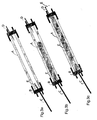
- Tubes made using the invention were synthesized in custom-built disposable molds, are shown in Figures 1a to 4c.
- the mold which may be a glass tubing A with an inside diameter (ID) between 0.02 and 100 mm, was cut to a desired length in the order of tens of centimeters.
- a septum B currently made of rubber, was slipped over each end of the glass tube to serve as an injection port.
- the tubing A is filled using a needle D pushed through the upper injection port to permit the exit of air during liquid injection.
- the desired homogeneous liquid was injected via needle C through septum B at the lower end of the mold, displacing all of the air within the mold. Withdrawing the needles D, then C, results in a sealed, liquid filled mold.
- the sealed mold was placed into the chuck of a drill that had been mounted horizontally, using a spirit level.
- Figures 1b, 1c and 1d show alternative embodiments of differently shaped molds that may be used to produce differently shaped tubes.
- Figure 1d shows a mold with multiple variations in diameter along the length of the mold used to manufacture tubes with the same shape.
- Figure 2a shows a cylindrical mold containing inner surface features such as rectangular fins on the inner surface used to manufacture tubes with rectangular indentations in the outer wall of the tubes.
- Figure 2b shows a cylindrical mold containing inner surface features such as convex spherical lumps on the inner surface used to manufacture tubes with concave spherical indentations in the outer wall.
- Figure 2c shows a cylindrical mold containing inner surface features such as pointed dimples on the inner surface used to manufacture tubes with dimples in the outer wall of the tube.
- Figure 2d shows a cylindrical mold containing inner surface features such as concave spherical lumps on the inner surface used to manufacture tubes with these features embedded in the wall of the resulting tubes.
- the surface features can be of symmetrical or non-symmetrical order, and different surface features can be used in any combination.
- the inner surface of the mold can be modified using a surface treatment, physical or chemical, that affects the morphology of the wall of the hollow structure.
- a surface treatment physical or chemical, that affects the morphology of the wall of the hollow structure.
- the separated phase can be liquid-like in nature, it can be induced to bead, and form droplets on the inner surface, thereby influencing the wall morphology.
- the desired surface treatment can allow the separated phase to spread across the inner surface, also influencing the wall morphology.
- Figures 4a, 4b and 4c show various schemes for rotation of the filled mold (A).
- the mold A is inserted into a drill chuck (F) and rotation of mold is commenced.
- the filled mold (A) is attached to the two ends of a lathe (G) and rotation of mold is commenced.
- the filled mold (A) is inserted into an adapter (H) so it can be placed into a drill chuck (F) and rotation of mold is commenced.
- O-rings (I) maintain position of mold (A) inside the adapter (H).
- Figures 5a and 5b show the process of phase separation during rotation of the mold.
- the mold (A) filled with a homogeneous mixture (E) is rotated about an axis at a suitable speed to centrifuge the phase that will eventually separate.
- Figure 5b shows the mixture beginning to phase-separate during rotation.
- the dense phase (J) is centrifuged to the periphery of the mold where it adopts the shape of the mold (K).
- phase separation of the mixture was induced, creating at least two phases from the liquid inside the mold.
- Phase separation may result in either liquid-liquid or viscoelastic solid-liquid interfaces or both within the mold.
- Phase separation can be induced using a range of different techniques and environmental changes.
- the addition of a propagating radical to a homogeneous monomer solution can induce phase separation, as can changes in temperature, pH, exposure of the mold to light, electric and magnetic fields.
- phase-separated particles After inducing different phases within the homogeneous solution, one or more of the phases will be forced to the periphery if the densities of the phases are different.
- the phase-separated particles then gel together, through covalent or physical bonding, to form a three-dimensional network between the separated phase(s).
- the gelation of particles must commence at a finite time after the onset of phase separation within the process of the invention.
- a porous material can have an outer coating applied to it using this technology.
- a plug of porous material Prior to the injection of a homogeneous mixture into the mold, a plug of porous material is inserted into the mold ( Figure 8a). After insertion of the porous structure into the mold, a homogeneous mixture is injected into the mold and rotated at the desired speed. The phase-separated phase is centrifuged through the pores of the inserted plug, and forms a structure on the outer surface of the porous plug, therefore sealing the material, without blocking the internal pores.
- the homogenous solution includes at least two or more phases, one being a monomer, or polymer, and the other a solvent.
- the initiation agent may be free radical initiators, thermal initiators and redox initiators.
- initiators includes ammonium persulfate or potassium persulfate with sodium metabisulfite, or tetramethylethylene diamine or ascorbic acid, azonitriles and derivatives thereof, alkyl peroxides and derivatives thereof, acyl peroxides and derivatives thereof, hydroperoxides and derivatives thereof; ketone peroxides and derivatives thereof, peresters and derivatives thereof and peroxy carbonates and derivatives thereof.
- the homogeneous solution could also include a cross-linking agent depending on the structure of the final product that is desired and the polymer material that is formed.
- the crosslinking agent may be a multifunctional molecule with at least two reactive functionalities and includes multi-functional methacrylates or multi-functional acrylates, multi-functional acrylamides or multi-funtional methacrylamides, or multi-functional star polymers of polyethylene glycol and preferably, but not limited to, one of ethylene glycol dimethacrylate (EDMA), hexamethylene dimethacrylate (HDMA), poly(ethylene glycol) dimethacrylate, 1,5-hexadiene-3,4-diol (DVG), 2,3-dihydroxybutanediol 1,4-dimethacrylate (BHDMA), 1,4-butanediol dimethacrylate (BDMA), 1,5-hexadiene (HD), methylene bisacrylamide (MBAm) multi-functional star polymers of poly(ethylene oxide) or
- An exemplary, non-limiting list of monomers that may be in the homogeneous mixture includes any one of acrylates, methacrylates, and derivatives thereof such as, but not limited to, 2-hydroxyethyl methacrylate, methyl methacrylate, 2-polyethylene glycol ethyl methacrylate, ethyl acrylate, 2-hydroxyethyl acrylate, acrylic acid, methacrylic acid, 2-chloroethyl methacrylate, butyl methacrylate, glycidyl methacrylate, hydroxypropyl methacrylate; acrylamides and derivatives thereof such as, but not limited to, methacrylamide, hydroxypropyl methacrylamide, N,N-diethyl acrylamide, N,N-dimethyl acrylamide, 2-chloroethyl acrylamide, 2-nitrobutyl acrylamide, ; N-vinyl pyrrolidone, acenaphthalene, N-vinyl ace
- a non-limiting exemplary list of solvents in the homogeneous mixture for the monomer and/or polymers includes any neucleophilic or electrophilic molecule including, but not necessarily restricted to water, alcohols, ethylene glycol, ethanol, acetone, poly(ethylene glycol), dimethyl sulfoxide, dimethyl formamide, alkanes and derivatives thereof, acetonitrile, acetic acid, benzene, acetic anhydride, benzyl acetate, carbon tetrachloride, chlorobenzene, n-butanol, 2-chloroethanol, chloroform, cyclohexane, cyclohexanol, dichloromethane, diethyl ether, di(ethylene glycol), di(ethylene glycol) monomethyl ether, 1,4 dioxane, N,N, dimethyl acetamide, N,N, dimethyl formamide, ethyl acetate, formaldehyde, n-heptane,
- the solvent can be chosen to solubilize the monomer but not a polymer or crosslinked polymer formed from the monomer.
- One of the components may include a polymer dissolved in a solvent.
- a tapered hollow structure with changing dimensions along it length can be manufactured where the sealed mold is rotated at a predetermined angle between 0 and 90° from the horizontal plane.
- controlling the viscoelastic properties of the separated phase and/or the rotation speed can create cell-invasive hollow structures. If the separated phase has substantial elastic properties, they will not coalesce, and after gelation, the porous network between the phase is large enough for the penetration of cells into the construct.
- multi-layered structures can be formed by repeating the process as many times as desired. After forming the first layer, the solvent phase can be removed and another homogeneous mixture injected into the mold. The first layer coating the mold, effectively becomes the mold for the next coating and the second formation penetrates into the first coating, binding them together after gelation.
- the multi-layered hollow structures can be manufactured using any or all of the types of tubes described in the examples, made from any material, similar or different materials, in any order required, as many times as required.
- a layered wall structure ie. gel-like and porous
- the wall structure can serve as a reservoir for the drug, which may be incorporated in another material/drug reservoir, such as microspheres releasing the drug.
- the drug may be delivered uniformly or in a gradient. By tuning the set-up, a gradient can be established.
- the drug may include, but is not limited to, proteins, peptides, genes, vectors, growth factors, hormones, oligonucleotides, cell products, or cells or combinations thereof.
- hollow structures that allow molecules to diffuse across the wall structure.
- hollow structures can be produced that selectively allow the diffusion of molecules based on size and/or shape to diffuse across the wall structure and to allow preferential directional drug delivery.
- the invention can also provide tubular structures with the appropriate mechanical properties for their end use - for example to match the mechanical properties of the tissue in which they are to be implanted.
- the present method can be used to produce tubular structures that have an outer gel phase and an inner porous phase.
- the present method can also be used to provide a tubular structure with overlapping regions of porous phase/gel phase.
- a significant advantage of the present method can be used to make hollow structures of various dimensions with internal diameters from 10 ⁇ m to 100cm.
- the present invention will now be illustrated with several non-limiting examples.
- the first examples relate to 2-hydroxyethyl methacrylate polymers and copolymers that are synthesized (and crosslinked) in a rotating mold where phase separation precedes gelation of polymer networks formed, resulting in a tube due to centrifugal forces.
- Such morphologies given as examples of 2-hydroxyethyl methacrylate and its copolymers are also relevant to any monomeric or polymeric system that can be induced to phase separate in a liquid-filled rotating mold.
- HEMA 2-hydroxyethyl methacrylate
- a crosslinking agent preferably, but not limited to ethylene dimethacrylate (EDMA)
- EDMA ethylene dimethacrylate
- APS ammonium persulfate
- SMBS sodium metabisulfite
- the appropriate volume of 10% SMBS solution was added to this mixture, which was mixed for an additional 30 seconds.
- the homogeneous monomer mixture was then drawn into a Luer-lok syringe using a 20-gauge needle.
- the needle was removed from the syringe and, using a new 20-gauge needle and a 0.8 ⁇ m filter, the monomer mixture was injected into the polymerization molds.
- the sealed mold was placed in the chuck of a RZR-1 dual range, variable speed stirring drill (Heidolph, Germany) that had been mounted horizontally, using a spirit level.
- the rotational speed was 2700 rpm as listed in Table 1.
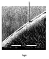
- the resulting gel-like coating on the inner surface of the mold is shown in Figure 6 and is approximately 10 ⁇ 3 ⁇ m thick.
- Figure 6 shows an environmental scanning electron microscope (ESEM) micrograph of a gel-like coating on the inside of a glass mold, in which the mixture formulation was 1% HEMA, 99% water, 0.01 %APS, 0.01% SMBS, 4000 rpm.
- ESEM environmental scanning electron microscope
- Example 2 A coating with both gel-like and porous morphologies was prepared with the same methodology as Example 1; the monomer mixture used also included poly(ethylene glycol) methacrylate as a comonomer.
- the monomer mixture and rotation.conditions used in Example 2 are listed in Table 1.
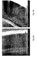
- the resulting porous materiallgel-like hybrid coating on the inner surface of the mold is shown in Figures 7a and 7b with the outer gel-like coating (the surface that is against the inside of the mold) facing forward in Figure 7a and the inner porous structure (the one against the water) facing forward in Figure 7b.
- the thickness of the coating is approximately 30 ⁇ 5 ⁇ m thick.
- the micrograph in Figures 7a and 7b were taken after removing the coating from the glass mold.
- Figure 7a shows a scanning electron microscope (SEM) micrograph of the outer surface of a porous coating applied to the inside of a glass mold, in which the mixture is 1.9% HEMA, 0.1% PEGMA, 98% water, 0.02% APS, 0.02% SMBS, 2700 rpm.
- Figure 7b shows the inner surface of a porous coating applied to the inside of a glass mold, in which the mixture formulation is 1.9% HEMA, 0.1 % PEGMA, 98% water, 0.02% APS, 0.02% SMBS, 2700 rpm.
- a porous material can have an outer coating applied to it using this technology.
- the coating that can be either gel-like or have porous morphology or both was prepared with similar methodology as in Example 1.
- a plug of porous material Prior to the injection of a homogeneous mixture into the mold, a plug of porous material is inserted into the mold ( Figure 8a).
- Porous PLGA is manufactured using techniques previously described (Holy et al, Biomaterials, 20, 1177-1185, 1999), however the porous material may be made of any material, including polymers, ceramics, metals; composites, or combinations thereof.
- the homogeneous mixture listed in Table 1 as Example 3 is injected into the mold and the mold rotated at the speed listed in Table 1.
- a porous, cell-invasive tube can be manufactured with the same methodology as Example 1, except the monomer mixture used may include methyl methacrylate (MMA) as a comonomer.
- Example 5 also substitutes TEMED for SMBS as the second component in the initiating system.
- the monomer mixture and rotation conditions used in Examples 4-5 are listed in Table 1, and both result in cell invasive, porous tubes.
- a faster initiating system such as, but not limited to the APS/TEMED redox system, or increased concentrations of initiator in the homogeneous mixture is beneficial to achieve the porous structure.
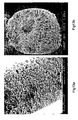
- Figures 9a and 9b show a porous wall morphology of Examples 4 and 5. Formation is due to sudden phase separation, in addition to viscoelastic particles separating, that do not coalesce.
- a semi-porous, cell-impermeable tube can be manufactured with the same methodology as Example 1, except the monomer mixture used may include methyl methacrylate (MMA) as a comonomer.
- MMA methyl methacrylate
- the monomer mixture and rotation conditions used in Examples 6-7 are listed in Table 1, and both result in semipermeable non-cell invasive, tubes.
- the rotation speed is at 10,000 rpm; the high rotation speed compacts the phase separating structure against the tube wall, resulting in gel-like wall morphology with closed cell pores that affect diffusion across the wall membrane (Figure 10a).
- the initiating system as a phase separating agent may be in a lower concentration, as slower phase separation is beneficial to achieve the non-porous, gel-like structure at lower rotation speeds (Figure 10b).
- a mixed porous/gel-like tube can be manufactured with the same methodology as Example 1, except the monomer mixture used may include MMA and/or ethylene glycol EG) which affects phase separation.
- the monomer mixture and rotation conditions used in Examples 8-9 are listed in Table 1, and both result in mixed porous and gel-like tubes manufactured with one polymerization.
- the bi-layer morphology of the cross-section of Example 8, seen in Figure 11a is due to the precipitation of a liquid-like phase at the start of the phase separation followed by a viscoelastic precipitate towards the end of the phase separation.
- Co-solvents other than water, such as EG are therefore useful for delaying or accelerating phase separation, and therefore control the bilayered morphology of the wall.
- Example 9 a porous/gel-like tube can be manufactured with the same methodology as Example 1, except faster speeds in combination with slower phase separation can induce the morphology in Figure 11b.
- a mixed porous/gel-like tube with radial porosity can be manufactured with the same methodology as Example 1, when the denser separating phase can be beaded as droplets on the inner surface of the rigid mold.
- the contact angle of the separating phase can be influenced by surface modification of the rigid mold, or changing the material of the inside of the mold.
- the wall morphology can therefore be influenced by the surface chemistry of the mold.
- the monomer mixture and rotation conditions used in Example 10 are listed in Table 1, may include co-solvents such as methyl methacrylate or ethylene glycol to influence the solubility of the separated phase.
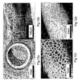
- Figures 12a and 12b are micrographs of the porous/gel-like tube with radial porosity cross-section, with Figure 12c showing the outer longitudinal morphology of the same formulation.
- the hollow structure shown in the optical micrograph in Figure 12d was synthesized with the same formulation as Example 10, but was formed in a silane-treated glass mold.
- the silanating agent was Sigmacote from Sigma-Aldrich.
- the Sigmacote solution was drawn up into glass molds and then dried in an oven to evaporate the solvent.
- Contact angle studies on glass slides showed the water contact angle changed from 44.7 ⁇ 3°/11.6 ⁇ 1.8° to 47 ⁇ 0.3°/44 ⁇ 0.4° after surface modification.
- the glass mold was then used with the formulation listed as Example 10 in Table 1.
- the hollow fiber membranes had equilibrium water contents between 42% and 57%; elastic moduli between 22 kPa and 400 kPa, and diffusive permeabilities between 10 -7 and 10 -9 cm 2 s -1 for vitamin B12 and dextran 10kD. Similar mechanical strengths of the tube walls could be achieved with significantly different permeabilities, reflecting their intrinsic microstructures. The beading described in Example 10 permits highly diffusive hollow structures while maintaining good mechanical strength.
- a porous tube with pores that are radial in nature can be manufactured with the same methodology as Example 1, with a monomer formulation mixture and rotation conditions listed in Table 1 as Example 11.
- the wall morphology is predominantly gel, with channels or pores that penetrate in a radial manner that does not require beading as in Example 10.
- An example of this morphology is shown in Figure 13a.
- a porous tube with fibers that are radial can be manufactured with the same methodology as Example 1, with a monomer formulation mixture and rotation conditions listed in Table 1 for Example 12.
- the wall morphology is predominantly space, with fibers that penetrate in a radial manner.
- the inner lumen of the formed hollow structure is small relative to the wall thickness and an example of this morphology is shown in Figure 13b.
- the prevention of sedimentation of low concentrations was achieved with a slow rotation rate.
- This surprising result demonstrates the profound effect of rotation rate on the wall morphology, especially compared to Example 2 ( Figure7a and 7b) which has the similar monomer concentrations, but significantly different rotation rates.
- Multi-layered hollow structures are possible by forming one layer and using the formed hollow structure as the surface coating of the mold and the hollow structure process repeated as many times as desired.
- the multi-layered hollow structures can be manufactured using any or all of the types of tubes described in the examples, made from any material, similar or different materials, in any order required, as many times as required. An example is shown in Figure 14.
- Example 14 Smooth surface morphology the inner layer of a tube with the mixture formulation listed in Table 1 as Example 14 can be manufactured with the same methodology as Example 1.
- a tube with a smooth inner surface is shown in Figure 15.
- Dimpled/rough surface morphology on the inner layer of a tube which can be made using the mixture formulation listed in Table 1 as example 15, can be manufactured with the same methodology as Example 1.
- a tube with a dimpled/rough inner surface is shown in Figure 16a.
- a lateral cross-section of the tube showing a gel-like/porous wall morphology and a dimpled/rough inner surface is shown in Figure 16b.
- Very small diameter micro-tubes can be manufactured with the same methodology as Example 1, except the mold size is very narrow.
- Figure 18 is a tube that was manufactured from a mixture formulation listed in Table 1 as example 17 in small diameter capillary tubing with an internal diameter of 450 ⁇ m. Smaller tubing can be created by using molds with an internal diameter of 10 ⁇ m and larger.
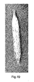
- Figure 19 is a tube that was manufactured from a mixture formulation listed in Table 1 as example 18, in a mold with a variable diameter. Any example formulation can be used to create this shape of hollow structure.
- a tapered hollow structure with changing dimensions along it length can be manufactured with the same methodology as example 1, except the sealed mold was placed into the chuck of a drill that had been mounted at a predetermined angle between 0 and 90° from the horizontal plane.
- a hollow structure with variable wall thickness or holes along the length can be manufactured with the same methodology as example 1, except the sealed mold has some inner surface morphologies, such as in Figure 2a-d. Any example formulation can be used to create this shape of hollow structure.
- Hollow structures can be manufactured from the liquid-liquid phase separation of a polymer solution using temperature as the phase separating agent.
- Poly(lactic-co-glycolic acid) was dissolved in a 87:13 (wt%) dioxane/water mixture at 60°C to create a solution that is injected into pre-heated glass molds. After injecting in a sealed glass mold, removing all air from the mold, it was placed in the chuck of a drill at room temperature and spun at 4000 rpm. The mold was allowed to cool to room temperature, which induced liquid-liquid phase separation and gelation. The mold was then frozen and the dioxane/water mixture removed by placing in a freeze-dryer. The formed tube is then removed from the mold.
- N-2-(hydroxypropyl) methacrylamide (30 vol%) was polymerized in the presence of excess acetone/dimethyl sulfoxide (DMSO) (93:7 v/v), with a crosslinking agent, preferably, but not limited to methylene bisacrylamide (1 mol%), using azobisisobutyronitrile (AIBN) as an initiating system.
- a crosslinking agent preferably, but not limited to methylene bisacrylamide (1 mol%)
- AIBN azobisisobutyronitrile
- a monomeric sugar may or may not be also added to the polymerization mixture.
- the mixture was fully mixed, and injected into a cylindrical glass mold as described for Example 1 using the mixture formulation listed in Table 1 as example 22.
- the sealed mold was placed in the chuck of a stirring drill that had been mounted horizontally, using a spirit level and rotated at 4000 rpm at 50°C for 24 hours.
- the resulting hollow structure on the inner surface of the mold is removed from the mold.
Landscapes
- Health & Medical Sciences (AREA)
- Engineering & Computer Science (AREA)
- Mechanical Engineering (AREA)
- Chemical & Material Sciences (AREA)
- Animal Behavior & Ethology (AREA)
- Veterinary Medicine (AREA)
- Medicinal Chemistry (AREA)
- Pharmacology & Pharmacy (AREA)
- Epidemiology (AREA)
- Life Sciences & Earth Sciences (AREA)
- Bioinformatics & Cheminformatics (AREA)
- General Health & Medical Sciences (AREA)
- Public Health (AREA)
- Nanotechnology (AREA)
- Moulding By Coating Moulds (AREA)
- Artificial Filaments (AREA)
- Manufacture Of Porous Articles, And Recovery And Treatment Of Waste Products (AREA)
- Extraction Or Liquid Replacement (AREA)
- Lubricants (AREA)
- Farming Of Fish And Shellfish (AREA)
- Structures Of Non-Positive Displacement Pumps (AREA)
Claims (28)
- Verfahren für das Herstellen eines Produkts, umfassend:a) das Füllen eines Innenraums einer Form (A) mit einer Lösung (E) derart, dass im Wesentlichen die gesamte Luft daraus verdrängt wird, wobei die Lösung (E) mindestens zwei Komponenten umfasst, die durch ein Phasentrennungsmittel in mindestens zwei Phasen phasengetrennt werden können;b) das Rotieren der Form (A), die die Lösung (E) enthält, mit einer wirksamen Rotationsgeschwindigkeit in Gegenwart des Phasentrennungsmittels, um die Phasentrennung zwischen den mindestens zwei Komponenten in mindestens zwei Phasen auszulösen, derart, dass unter Rotation mindestens eine der Phasen (J) sich auf einer Innenfläche (K) der Form (A) absetzt undc) das Bilden des Produkts durch Stabilisieren mindestens einer der Phasen (J), die auf der Innenfläche (K) der Form (A) abgesetzt worden ist.
- Verfahren nach Anspruch 1 umfassend das Entfernen des Produkts von der Form.
- Verfahren nach Anspruch 1 oder 2, wobei die mindestens zwei Komponenten mindestens ein Monomer und mindestens ein Lösungsmittel umfassen und wobei die Lösung eine im Wesentlichen homogene Lösung ist, wobei mindestens eine der Phasen, die auf der Innenfläche abgesetzt werden, mindestens das Monomer umfasst und wobei der Schritt des Stabilisierens der abgesetzten Phase die Gelbildung des Monomers durch Polymerisation desselben umfasst.
- Verfahren nach Anspruch 3, wobei das Phasentrennungsmittel aus der Gruppe ausgewählt ist bestehend aus Licht, pH-Wert, Initiatoren, Änderung der Temperatur, Bildung eines chemischen Produkts innerhalb der Form, Änderungen der kationischen und/oder anionischen Konzentrationen, elektrischen und magnetischen Feldern.
- Verfahren nach Anspruch 4, wobei der Initiator aus der Gruppe ausgewählt ist bestehend aus Radikalinitiatoren, Wärme- und Fotoinitiatoren und Redoxinitiatoren.
- Verfahren nach Anspruch 1 oder 2, wobei mindestens zwei Komponenten mindestens ein Polymer umfassen, das in mindestens einem Lösungsmittel gelöst ist, und wobei die Lösung eine im Wesentlichen homogene Lösung ist, wobei mindestens eine der Phasen, die auf der Innenfläche abgesetzt werden, mindestens das Polymer umfassen und wobei der Schritt des Stabilisierens der abgesetzten Phase die Gelbildung derselben umfasst.
- Verfahren nach Anspruch 6, wobei das Phasentrennungsmittel aus der Gruppe ausgewählt ist bestehend aus Licht, pH-Wert, Initiatoren, Änderung der Temperatur, Bildung eines chemischen Produkts innerhalb der Form, Änderungen der kationischen und/oder anionischen Konzentrationen, elektrischen und magnetischen Feldern.
- Verfahren nach Anspruch 6, wobei die Gelbildung durch Aussetzen einem Mittel gegenüber erreicht wird, das aus der Gruppe ausgewählt ist Licht, pH-Wert, Initiatoren, Änderung der Temperatur, Bildung eines chemischen Produkts innerhalb der Form, Änderungen der kationischen und/oder anionischen Konzentrationen, elektrischen und magnetischen Feldern.
- Verfahren nach den Ansprüchen 3 oder 6, wobei die hohle Form eine zylindrische Röhre ist, derart, dass das Produkt eine polymere Röhre ist.
- Verfahren nach Anspruch 9, wobei die zylindrische Röhre vorgewählte Oberflächenmerkmale auf der Innenfläche der zylindrischen Röhre umfasst.
- Verfahren nach den Ansprüchen 1 oder 2 umfassend das Einsetzen einer porösen Struktur in die Form vor dem Füllen der Form mit der Lösung und wobei das Produkt schichtförmig auf eine Außenfläche der porösen Struktur aufgebracht wird.
- Verfahren nach den Ansprüchen 3 oder 6, wobei die Lösung ein Vernetzungsmittel umfasst.
- Verfahren nach Anspruch 12, wobei das Vernetzungsmittel aus der Gruppe ausgewählt ist bestehend aus einem multifunktionellen Methacrylat, Acrylat, Acrylamid, Methacrylamid, 1,5-Hexadien-3,4-diol, multifunktionellen 1,5-Hexadien-(HD-)Sternpolymeren von Poly(ethylenoxid).
- Verfahren nach Anspruch 3, wobei das Monomer aus der Gruppe ausgewählt ist bestehend aus Acrylaten, Methacrylaten, Acrylsäure, Methacrylsäure, Acrylamid, Methacrylamid und Derivaten derselben; N-Vinylpyrrolidon, Acenaphthalin, N-Vinylacetamid, Phenylacetylen, Acrolein, Methylacrolein, N-Vinylpyridin, Vinylacetat, Vinylchlorid, Vinylfluorid, Vinylmethylketon, Vinylidenchlorid, Styrol und Derivaten desselben, Propen, Acrylnitril, Methacrylnitril, Acryloylchlorid, Allylacetat, Allylchlorid, Allylbenzol, Butadien und Derivaten derselben, N-Vinylcaprolactam, N-Vinylcarbazol, Cinnamaten und Derivaten derselben, Citraconimid und Derivaten desselben, Crotonsäure, Diallylphthalat, Ethylen und Derivaten desselben; Fumaraten und Derivaten derselben, Hexen und Derivaten desselben, Isopren und Derivaten desselben; Itaconat und Derivaten desselben; Itaconamid und Derivaten desselben; Diethylmaleat, 2-(Acryloyloxy)ethyldiethylphosphat, Vinylphosphonaten und Derivaten derselben; Maleinsäureanhydrid, Maleimid, Siliconmonomeren und Derivaten derselben und irgendeiner Kombination derselben.
- Verfahren nach Anspruch 3 oder 6, wobei das Lösungsmittel aus der Gruppe ausgewählt ist bestehend aus nucleophilen oder elektrophilen Molekülen ausgewählt aus der Gruppe bestehend aus Wasser, Alkoholen, Ethylenglykol, Ethanol, Aceton, Poly(ethylenglykol), Dimethylsulfoxid, Dimethylformamid, Alkanen und Derivaten derselben, Acetonitril, Essigsäure, Benzol, Essigsäureanhydrid, Benzylacetat, Tetrachlorkohlenstoff, Chlorbenzol, n-Butanol, 2-Chlorethanol, Chloroform, Cyclohexan, Cyclohexanol, Dichlormethan, Diethylether, Di(ethylenglykol), Di(ethylenglykol)monomethylether, 1,4-Dioxan, N,N'-Dimethylacetamid, N,N'-Dimethylformamid, Ethylacetat, Formaldehyd, n-Heptan, Hexachlorethan, Hexan, Isobutanol, Isopropanol, Methanol, Methylethylketon, Nitrobenzol, n-Octan, n-Pentanol, Propylacetat, Propylenglykol, Pyridin, Tetrahydrofuran, Toluol, Trichlorethylen, o-Xylol und p-Xylol, einem Monomer, einem flüssigen Vernetzungsmittel oder Mischungen derselben.
- Verfahren nach Anspruch 3, wobei das Lösungsmittel das Monomer, jedoch kein Polymer oder aus dem Monomer gebildetes vernetztes Polymer löslich macht.
- Verfahren nach Anspruch 3, wobei mindestens ein Monomer im Bereich von circa 0,001 Gew.-% bis circa 60 Gew.-% vorliegt.
- Verfahren nach Anspruch 6, wobei das Polymer aus der Gruppe ausgewählt ist bestehend aus Polyacrylaten, Polysulfonen, Peptidsequenzen, Proteinen, Oligopeptiden, Collagen, Fibronectin, Laminin, Polymethacrylaten, Polyacetaten, Polyestern, Polyamiden, Polycarbonaten, Polyanhydriden, Polyaminosäuren, Cellulose, Hyaluronsäure, Natriumhyaluronat, Alginat, Agarose, Chitosan, Chitin und Mischungen derselben.
- Verfahren nach Anspruch 1 umfassend das physikalische oder chemische Modifizieren der Innenfläche der Form auf der durch Induzieren der Perlbildung oder des Ausbreitens der abgetrennten flüssigen Phase vorgewählte Morphologien in die Wand des Produkts induziert werden.
- Verfahren nach Anspruch 19 mit Molekülen, die Silaniermittel umfassen.
- Verfahren nach den Ansprüchen 3 oder 6, einschließlich des Schritts des Entfernens des Lösungsmittels und einschließlich des Wiederholens der Schritte a), b) und c) mindestens einmal zur Bildung eines mehrschichtigen Produkts.
- Verfahren nach Anspruch 19, wobei die vorgewählten Wandmorphologien aus einer Gruppe ausgewählt sind bestehend aus einer porösen Struktur, einer Gelstruktur und überlappenden Bereichen einer porösen/Gelstruktur.
- Verfahren nach Anspruch 19, wobei die vorgewählten Wandmorphologien eine überwiegende Gelmorphologie mit porösen Kanälen umfassen, die von einer Peripherie zu einer Lumenseite führen, was zur Fleckenbildung auf einer äußeren Wandfläche führt.
- Verfahren nach Anspruch 19, wobei die Wandstruktur als Reservoir für die Abgabe von Arzneimitteln, Therapeutika, Zellen, Zellprodukten, Genen, Virenvektoren, Proteinen, Peptiden, Hormonen, Kohlehydraten, Wachstumsfaktoren verwendet werden.
- Verfahren nach Anspruch 1, wobei die Lösung Mikrosphären enthält, die vorgewählte Bestandteile enthalten, und wobei das Produkt die Mikrosphären entweder gleichförmig verteilt oder in einem Gradienten innerhalb der Wandstruktur des Produkts enthält.
- Verfahren nach Anspruch 12, wobei das Vernetzungsmittel aus der Gruppe ausgewählt ist bestehend aus Ethylenglykoldimethacrylat (EDMA), Hexamethylendimethacrylat (HDMA), Poly(ethylenglykol)dimethacrylat, 2,3-Dihydroxybutandiol-1,4-dimethacrylat (BHDMA) und 1,4-Butandioldimethacrylat (BDMA).
- Verfahren nach Anspruch 3, wobei das Monomer aus der Gruppe ausgewählt ist bestehend aus 2-Hydroxyethylmethacrylat, Methylmethacrylat, 2-Polyethylenglykolethylmethacrylat, Ethylacrylat, 2-Hydroxyethylacrylat, 2-Chlorethylmethacrylat, Butylmethacrylat, Glycidylmethacrylat, Hydroxypropylmethacrylat; Hydroxypropylmethacrylamid, N,N-Diethylacrylamid, N,N-Dimethylacrylamid, 2-Chlorethylacrylamid, 2-Nitrobutylacrylamid; 1,1-Diphenylethylen, Chlortrifluorethylen, Dichlorethylen, Tetrachlorethylen; Isopropenylacetat, Isopropenylmethylketon, Isopropenylisocyanat; und Kombinationen derselben.
- Verfahren nach Anspruch 6, wobei das Polymer aus der Gruppe ausgewählt ist bestehend aus Poly(methylmethacrylat), Poly(ethoxyethylmethacrylat), Poly(hydroxyethylmethacrylat); Poly(N-vinylpyrrolidon), Polyvinylacetat, Polyvinylalkohol, Poly(hydroxypropylmethacrylamid), Poly(caprolacton), Poly(dioxanon)polyglykolsäure, Polymilchsäure, Copolymeren von Milch- und Glykolsäuren und Polytrimethylencarbonaten, Poly(butadien), Polystyrol, Polyacrylnitril, Poly(chloropren), Neopren, Poly(isobuten), Poly(isopren), Polypropylen, Polytetrafluorethylen, Poly(vinylidenfluorid), Poly(chlortrifluorethylen), Poly(vinylchlorid), Poly(oxymethylen), Poly(ethylenterephthalat), Poly(oxyethylen)poly(oxyterephthaloyl); Poly[imino(1-oxohexamethylen)], Poly(iminoadipoyliminohexamethylen), Poly(iminohexamethyleniminosebacoyl), Poly[imino(1-oxodeodcamethylen)] und Mischungen derselben.
Applications Claiming Priority (3)
| Application Number | Priority Date | Filing Date | Title |
|---|---|---|---|
| US20391000P | 2000-05-12 | 2000-05-12 | |
| US203910P | 2000-05-12 | ||
| PCT/CA2001/000680 WO2001085417A1 (en) | 2000-05-12 | 2001-05-11 | Method of producing structures using centrifugal forces |
Publications (2)
| Publication Number | Publication Date |
|---|---|
| EP1303387A1 EP1303387A1 (de) | 2003-04-23 |
| EP1303387B1 true EP1303387B1 (de) | 2006-06-28 |
Family
ID=22755799
Family Applications (1)
| Application Number | Title | Priority Date | Filing Date |
|---|---|---|---|
| EP01931299A Expired - Lifetime EP1303387B1 (de) | 2000-05-12 | 2001-05-11 | Verfahren zur herstellung von strukturen durch gebrauch von zentrifugalen kräften |
Country Status (10)
| Country | Link |
|---|---|
| US (2) | US6787090B2 (de) |
| EP (1) | EP1303387B1 (de) |
| JP (1) | JP2003532556A (de) |
| AT (1) | ATE331599T1 (de) |
| AU (2) | AU5812701A (de) |
| CA (1) | CA2408638C (de) |
| DE (1) | DE60121170T2 (de) |
| ES (1) | ES2267764T3 (de) |
| PT (1) | PT1303387E (de) |
| WO (1) | WO2001085417A1 (de) |
Cited By (1)
| Publication number | Priority date | Publication date | Assignee | Title |
|---|---|---|---|---|
| US7722733B2 (en) | 2004-03-29 | 2010-05-25 | Baxter International Inc. | Method for sterile connection of tubing |
Families Citing this family (18)
| Publication number | Priority date | Publication date | Assignee | Title |
|---|---|---|---|---|
| US6969480B2 (en) * | 2000-05-12 | 2005-11-29 | Matregen Corp. | Method of producing structures using centrifugal forces |
| DE10205191C1 (de) * | 2002-02-08 | 2003-10-09 | Hobas Engineering Gmbh Klagenf | Im Schleuderverfahren hergestelltes mehrschichtiges Kunststoffrohr |
| US7332211B1 (en) * | 2002-11-07 | 2008-02-19 | Massachusetts Institute Of Technology | Layered materials including nanoparticles |
| US7837913B2 (en) * | 2004-08-11 | 2010-11-23 | California Institute Of Technology | High aspect ratio template and method for producing same |
| WO2006122414A1 (en) * | 2005-05-17 | 2006-11-23 | Matregen Corp. | Depot for sustained and controlled delivery of methotrexate |
| US20090035446A1 (en) * | 2005-09-06 | 2009-02-05 | Theraject, Inc. | Solid Solution Perforator Containing Drug Particle and/or Drug-Adsorbed Particles |
| WO2008058036A1 (en) * | 2006-11-03 | 2008-05-15 | R & D Green Materials, Llc | Process for preparing biodegradable articles |
| EP2135694A4 (de) * | 2007-03-15 | 2010-08-18 | Honda Motor Co Ltd | Hohlglied, zylinderhülse und herstellungsverfahren dafür |
| US20090326128A1 (en) * | 2007-05-08 | 2009-12-31 | Javier Macossay-Torres | Fibers and methods relating thereto |
| US8721319B2 (en) | 2008-03-17 | 2014-05-13 | Board of Regents of the University to Texas System | Superfine fiber creating spinneret and uses thereof |
| GB0811856D0 (en) * | 2008-06-27 | 2008-07-30 | Ucl Business Plc | Magnetic microbubbles, methods of preparing them and their uses |
| US8148445B1 (en) * | 2009-01-14 | 2012-04-03 | Novartis Ag | Ophthalmic and otorhinolaryngological device materials containing a multi-arm PEG macromer |
| US8329219B2 (en) | 2009-12-22 | 2012-12-11 | Cook Biotech Incorporated | Methods for producing ECM-based biomaterials |
| US8647541B2 (en) | 2011-02-07 | 2014-02-11 | Fiberio Technology Corporation | Apparatuses and methods for the simultaneous production of microfibers and nanofibers |
| US9457398B2 (en) | 2011-06-10 | 2016-10-04 | Jean-Paul Ciardullo | Spherical centrifuge |
| US9913804B2 (en) | 2015-12-31 | 2018-03-13 | Incube Labs, Llc | Solid drug storage apparatus, formulations and methods of use |
| CA3074944A1 (en) | 2017-09-08 | 2019-03-14 | Board Of Regents Of The University Of Texas System | Mechanoluminescence polymer doped fabrics and methods of making |
| US11427937B2 (en) | 2019-02-20 | 2022-08-30 | The Board Of Regents Of The University Of Texas System | Handheld/portable apparatus for the production of microfibers, submicron fibers and nanofibers |
Family Cites Families (17)
| Publication number | Priority date | Publication date | Assignee | Title |
|---|---|---|---|---|
| DE1514410A1 (de) * | 1951-01-28 | 1969-10-02 | Siemens Ag | Verfahren zum Herstellen von Rotationskoerpern mit einer magnetischen Randzone |
| GB1380262A (en) * | 1971-03-10 | 1975-01-08 | Ici Ltd | Shaped articles |
| CH644768A5 (de) * | 1977-08-25 | 1984-08-31 | Sandoz Ag | Verfahren zur herstellung von mikrokugeln. |
| DE3406148A1 (de) * | 1984-02-21 | 1985-09-05 | Philips Patentverwaltung Gmbh, 2000 Hamburg | Verfahren zur herstellung von rohrfoermigen koerpern und vorrichtung zur durchfuehrung des verfahrens |
| US4666640A (en) * | 1986-02-13 | 1987-05-19 | Neefe Charles W | Method of making a spin cast gradient light absorbing contact lens |
| GB8621322D0 (en) | 1986-09-04 | 1986-10-15 | Mcdonald P J | Imaging solids |
| JPH01247435A (ja) * | 1988-03-28 | 1989-10-03 | Sekisui Chem Co Ltd | 多孔体の製造方法 |
| US5094895A (en) * | 1989-04-28 | 1992-03-10 | Branca Phillip A | Composite, porous diaphragm |
| AU651654B2 (en) * | 1992-01-14 | 1994-07-28 | Endo Pharmaceuticals Solutions Inc. | Manufacture of water-swellable hydrophilic articles and drug delivery devices |
| US5266325A (en) | 1990-09-28 | 1993-11-30 | Hydro Med Science Division Of National Patent Development Corp. | Preparation of homogeneous hydrogel copolymers |
| JPH04348117A (ja) | 1991-07-17 | 1992-12-03 | Mitsubishi Rayon Co Ltd | ポリオルガノシロキサン系グラフト共重合体 |
| KR950002826B1 (ko) * | 1991-08-09 | 1995-03-27 | 한국과학기술연구원 | 열유도 상분리법을 이용한 다공성 폴리올레핀 분리막의 제조방법 |
| JPH06202087A (ja) * | 1992-12-28 | 1994-07-22 | Sumitomo Electric Ind Ltd | 複合膜の製造方法および液晶素子 |
| US5532282A (en) * | 1994-12-16 | 1996-07-02 | Neeco, Inc. | Polyolefin-based composition for rotational molding |
| US5868976A (en) | 1997-03-14 | 1999-02-09 | Koch Membrane Systems, Inc. | Process of making a dialysis membrane |
| US6090486A (en) * | 1999-04-22 | 2000-07-18 | Virginia Polytechnic Institute & State University | Fiber materials for manufacturing fiber reinforced phenolic composites and adhesives with nucleophilic initiators positioned on the fiber surfaces |
| US6589470B2 (en) * | 1999-04-26 | 2003-07-08 | Robert P. Fried | Process for producing molded plastic articles |
-
2001
- 2001-05-11 DE DE60121170T patent/DE60121170T2/de not_active Expired - Fee Related
- 2001-05-11 AT AT01931299T patent/ATE331599T1/de not_active IP Right Cessation
- 2001-05-11 US US10/169,948 patent/US6787090B2/en not_active Expired - Fee Related
- 2001-05-11 AU AU5812701A patent/AU5812701A/xx active Pending
- 2001-05-11 AU AU2001258127A patent/AU2001258127B2/en not_active Ceased
- 2001-05-11 EP EP01931299A patent/EP1303387B1/de not_active Expired - Lifetime
- 2001-05-11 JP JP2001582052A patent/JP2003532556A/ja active Pending
- 2001-05-11 PT PT01931299T patent/PT1303387E/pt unknown
- 2001-05-11 WO PCT/CA2001/000680 patent/WO2001085417A1/en active IP Right Grant
- 2001-05-11 ES ES01931299T patent/ES2267764T3/es not_active Expired - Lifetime
- 2001-05-11 CA CA002408638A patent/CA2408638C/en not_active Expired - Fee Related
-
2004
- 2004-08-02 US US10/903,384 patent/US20050003127A1/en not_active Abandoned
Cited By (2)
| Publication number | Priority date | Publication date | Assignee | Title |
|---|---|---|---|---|
| US7722733B2 (en) | 2004-03-29 | 2010-05-25 | Baxter International Inc. | Method for sterile connection of tubing |
| US8162021B2 (en) | 2004-03-29 | 2012-04-24 | Baxter International | Apparatus for sterile connection of tubing |
Also Published As
| Publication number | Publication date |
|---|---|
| CA2408638A1 (en) | 2001-11-15 |
| DE60121170D1 (de) | 2006-08-10 |
| US20050003127A1 (en) | 2005-01-06 |
| PT1303387E (pt) | 2006-10-31 |
| US6787090B2 (en) | 2004-09-07 |
| JP2003532556A (ja) | 2003-11-05 |
| CA2408638C (en) | 2009-07-28 |
| EP1303387A1 (de) | 2003-04-23 |
| AU2001258127B2 (en) | 2005-11-10 |
| ATE331599T1 (de) | 2006-07-15 |
| ES2267764T3 (es) | 2007-03-16 |
| US20030039777A1 (en) | 2003-02-27 |
| AU5812701A (en) | 2001-11-20 |
| WO2001085417A1 (en) | 2001-11-15 |
| DE60121170T2 (de) | 2007-05-16 |
Similar Documents
| Publication | Publication Date | Title |
|---|---|---|
| EP1303387B1 (de) | Verfahren zur herstellung von strukturen durch gebrauch von zentrifugalen kräften | |
| US6969480B2 (en) | Method of producing structures using centrifugal forces | |
| AU2001258127A1 (en) | Method of producing structures using centrifugal forces | |
| US6331578B1 (en) | Process for preparing interpenetrating polymer networks of controlled morphology | |
| WO2006122414A1 (en) | Depot for sustained and controlled delivery of methotrexate | |
| US6074718A (en) | Self supporting hollow fiber membrane and method of construction | |
| US5202025A (en) | Porous membrane and method for preparing the same | |
| US9458357B2 (en) | ph-sensitive sacrificial materials for the microfabrication of structures | |
| EP1413350A1 (de) | Mehrschichtige, mikroporöse folie | |
| CN1112775A (zh) | 医疗用材料及其制造方法 | |
| JPWO2007018284A1 (ja) | 親水化剤によって親水化された芳香族エーテル系高分子からなる液体処理分離膜 | |
| JPH0628705B2 (ja) | 半透過性中空繊維膜の製造方法 | |
| EP0614923A1 (de) | Hydrophiles material, sowie daraus hergestelltes semipermeables membran | |
| Zhang et al. | A microfluidic approach to fabricate monodisperse hollow or porous poly (HEMA–MMA) microspheres using single emulsions as templates | |
| US7135230B2 (en) | Functional particle and preparing/plasma-treating method of the same | |
| CN109693324A (zh) | 一种聚合物微针模具的制作方法 | |
| JPH0451216B2 (de) | ||
| US20160039117A1 (en) | Method for Producing Shaped Polymeric Microparticles | |
| KR910009814B1 (ko) | 친수성 폴리프로필렌 다공질막, 그의 제조방법 및 혈장 분리장치 | |
| AU609879B2 (en) | Hydrophilic porous membrane, process for its production and plasma-separating apparatus | |
| Vergaelen | Poly (2-oxazoline) s as matrix excipient for oral drug formulations | |
| JPH067652A (ja) | 中空糸型非対称多孔質膜及びその製造方法 | |
| O’Callaghan et al. | A microfluidic platform for the synthesis of polymer and polymer-protein-based protocells | |
| JPH1057787A (ja) | 分離膜とその製造方法 | |
| CN106727425A (zh) | 一种溶菌酶plga微球的制备方法 |
Legal Events
| Date | Code | Title | Description |
|---|---|---|---|
| PUAI | Public reference made under article 153(3) epc to a published international application that has entered the european phase |
Free format text: ORIGINAL CODE: 0009012 |
|
| 17P | Request for examination filed |
Effective date: 20021212 |
|
| AK | Designated contracting states |
Designated state(s): AT BE CH CY DE DK ES FI FR GB GR IE IT LI LU MC NL PT SE TR |
|
| AX | Request for extension of the european patent |
Extension state: AL LT LV MK RO SI |
|
| 17Q | First examination report despatched |
Effective date: 20050118 |
|
| GRAP | Despatch of communication of intention to grant a patent |
Free format text: ORIGINAL CODE: EPIDOSNIGR1 |
|
| RAP1 | Party data changed (applicant data changed or rights of an application transferred) |
Owner name: MATREGEN CORP. |
|
| RIN1 | Information on inventor provided before grant (corrected) |
Inventor name: DALTON, PAUL D. Inventor name: SHOICHET, MOLLY S. |
|
| GRAS | Grant fee paid |
Free format text: ORIGINAL CODE: EPIDOSNIGR3 |
|
| GRAA | (expected) grant |
Free format text: ORIGINAL CODE: 0009210 |
|
| AK | Designated contracting states |
Kind code of ref document: B1 Designated state(s): AT BE CH CY DE DK ES FI FR GB GR IE IT LI LU MC NL PT SE TR |
|
| PG25 | Lapsed in a contracting state [announced via postgrant information from national office to epo] |
Ref country code: IT Free format text: LAPSE BECAUSE OF FAILURE TO SUBMIT A TRANSLATION OF THE DESCRIPTION OR TO PAY THE FEE WITHIN THE PRESCRIBED TIME-LIMIT;WARNING: LAPSES OF ITALIAN PATENTS WITH EFFECTIVE DATE BEFORE 2007 MAY HAVE OCCURRED AT ANY TIME BEFORE 2007. THE CORRECT EFFECTIVE DATE MAY BE DIFFERENT FROM THE ONE RECORDED. Effective date: 20060628 Ref country code: FI Free format text: LAPSE BECAUSE OF FAILURE TO SUBMIT A TRANSLATION OF THE DESCRIPTION OR TO PAY THE FEE WITHIN THE PRESCRIBED TIME-LIMIT Effective date: 20060628 |
|
| REG | Reference to a national code |
Ref country code: GB Ref legal event code: FG4D |
|
| REG | Reference to a national code |
Ref country code: CH Ref legal event code: EP |
|
| REG | Reference to a national code |
Ref country code: IE Ref legal event code: FG4D |
|
| REF | Corresponds to: |
Ref document number: 60121170 Country of ref document: DE Date of ref document: 20060810 Kind code of ref document: P |
|
| PG25 | Lapsed in a contracting state [announced via postgrant information from national office to epo] |
Ref country code: DK Free format text: LAPSE BECAUSE OF FAILURE TO SUBMIT A TRANSLATION OF THE DESCRIPTION OR TO PAY THE FEE WITHIN THE PRESCRIBED TIME-LIMIT Effective date: 20060928 Ref country code: SE Free format text: LAPSE BECAUSE OF FAILURE TO SUBMIT A TRANSLATION OF THE DESCRIPTION OR TO PAY THE FEE WITHIN THE PRESCRIBED TIME-LIMIT Effective date: 20060928 |
|
| REG | Reference to a national code |
Ref country code: PT Ref legal event code: SC4A Effective date: 20060811 |
|
| ET | Fr: translation filed | ||
| REG | Reference to a national code |
Ref country code: ES Ref legal event code: FG2A Ref document number: 2267764 Country of ref document: ES Kind code of ref document: T3 |
|
| PLBE | No opposition filed within time limit |
Free format text: ORIGINAL CODE: 0009261 |
|
| STAA | Information on the status of an ep patent application or granted ep patent |
Free format text: STATUS: NO OPPOSITION FILED WITHIN TIME LIMIT |
|
| PGFP | Annual fee paid to national office [announced via postgrant information from national office to epo] |
Ref country code: LU Payment date: 20070511 Year of fee payment: 7 |
|
| PGFP | Annual fee paid to national office [announced via postgrant information from national office to epo] |
Ref country code: MC Payment date: 20070514 Year of fee payment: 7 |
|
| PGFP | Annual fee paid to national office [announced via postgrant information from national office to epo] |
Ref country code: AT Payment date: 20070515 Year of fee payment: 7 Ref country code: CH Payment date: 20070515 Year of fee payment: 7 |
|
| PGFP | Annual fee paid to national office [announced via postgrant information from national office to epo] |
Ref country code: IE Payment date: 20070524 Year of fee payment: 7 |
|
| PGFP | Annual fee paid to national office [announced via postgrant information from national office to epo] |
Ref country code: BE Payment date: 20070531 Year of fee payment: 7 |
|
| 26N | No opposition filed |
Effective date: 20070329 |
|
| PG25 | Lapsed in a contracting state [announced via postgrant information from national office to epo] |
Ref country code: GR Free format text: LAPSE BECAUSE OF FAILURE TO SUBMIT A TRANSLATION OF THE DESCRIPTION OR TO PAY THE FEE WITHIN THE PRESCRIBED TIME-LIMIT Effective date: 20060929 |
|
| BERE | Be: lapsed |
Owner name: *MATREGEN CORP. Effective date: 20080531 |
|
| PG25 | Lapsed in a contracting state [announced via postgrant information from national office to epo] |
Ref country code: MC Free format text: LAPSE BECAUSE OF NON-PAYMENT OF DUE FEES Effective date: 20080531 |
|
| REG | Reference to a national code |
Ref country code: CH Ref legal event code: PL |
|
| PG25 | Lapsed in a contracting state [announced via postgrant information from national office to epo] |
Ref country code: CH Free format text: LAPSE BECAUSE OF NON-PAYMENT OF DUE FEES Effective date: 20080531 Ref country code: LI Free format text: LAPSE BECAUSE OF NON-PAYMENT OF DUE FEES Effective date: 20080531 |
|
| PG25 | Lapsed in a contracting state [announced via postgrant information from national office to epo] |
Ref country code: AT Free format text: LAPSE BECAUSE OF NON-PAYMENT OF DUE FEES Effective date: 20080511 |
|
| PGFP | Annual fee paid to national office [announced via postgrant information from national office to epo] |
Ref country code: PT Payment date: 20081111 Year of fee payment: 8 |
|
| PG25 | Lapsed in a contracting state [announced via postgrant information from national office to epo] |
Ref country code: BE Free format text: LAPSE BECAUSE OF NON-PAYMENT OF DUE FEES Effective date: 20080531 |
|
| PG25 | Lapsed in a contracting state [announced via postgrant information from national office to epo] |
Ref country code: IE Free format text: LAPSE BECAUSE OF NON-PAYMENT OF DUE FEES Effective date: 20080512 |
|
| PGFP | Annual fee paid to national office [announced via postgrant information from national office to epo] |
Ref country code: ES Payment date: 20090521 Year of fee payment: 9 Ref country code: NL Payment date: 20090527 Year of fee payment: 9 |
|
| PG25 | Lapsed in a contracting state [announced via postgrant information from national office to epo] |
Ref country code: CY Free format text: LAPSE BECAUSE OF FAILURE TO SUBMIT A TRANSLATION OF THE DESCRIPTION OR TO PAY THE FEE WITHIN THE PRESCRIBED TIME-LIMIT Effective date: 20060628 |
|
| PGFP | Annual fee paid to national office [announced via postgrant information from national office to epo] |
Ref country code: DE Payment date: 20090525 Year of fee payment: 9 Ref country code: FR Payment date: 20090515 Year of fee payment: 9 Ref country code: IT Payment date: 20090523 Year of fee payment: 9 |
|
| PG25 | Lapsed in a contracting state [announced via postgrant information from national office to epo] |
Ref country code: TR Free format text: LAPSE BECAUSE OF FAILURE TO SUBMIT A TRANSLATION OF THE DESCRIPTION OR TO PAY THE FEE WITHIN THE PRESCRIBED TIME-LIMIT Effective date: 20060628 |
|
| REG | Reference to a national code |
Ref country code: PT Ref legal event code: MM4A Free format text: LAPSE DUE TO NON-PAYMENT OF FEES Effective date: 20091111 |
|
| PGFP | Annual fee paid to national office [announced via postgrant information from national office to epo] |
Ref country code: GB Payment date: 20090522 Year of fee payment: 9 |
|
| PG25 | Lapsed in a contracting state [announced via postgrant information from national office to epo] |
Ref country code: PT Free format text: LAPSE BECAUSE OF NON-PAYMENT OF DUE FEES Effective date: 20091111 |
|
| PG25 | Lapsed in a contracting state [announced via postgrant information from national office to epo] |
Ref country code: LU Free format text: LAPSE BECAUSE OF NON-PAYMENT OF DUE FEES Effective date: 20080511 |
|
| REG | Reference to a national code |
Ref country code: NL Ref legal event code: V1 Effective date: 20101201 |
|
| GBPC | Gb: european patent ceased through non-payment of renewal fee |
Effective date: 20100511 |
|
| REG | Reference to a national code |
Ref country code: FR Ref legal event code: ST Effective date: 20110131 |
|
| PG25 | Lapsed in a contracting state [announced via postgrant information from national office to epo] |
Ref country code: IT Free format text: LAPSE BECAUSE OF NON-PAYMENT OF DUE FEES Effective date: 20100511 Ref country code: NL Free format text: LAPSE BECAUSE OF NON-PAYMENT OF DUE FEES Effective date: 20101201 |
|
| PG25 | Lapsed in a contracting state [announced via postgrant information from national office to epo] |
Ref country code: DE Free format text: LAPSE BECAUSE OF NON-PAYMENT OF DUE FEES Effective date: 20101201 |
|
| PG25 | Lapsed in a contracting state [announced via postgrant information from national office to epo] |
Ref country code: FR Free format text: LAPSE BECAUSE OF NON-PAYMENT OF DUE FEES Effective date: 20100531 |
|
| REG | Reference to a national code |
Ref country code: ES Ref legal event code: FD2A Effective date: 20110714 |
|
| PG25 | Lapsed in a contracting state [announced via postgrant information from national office to epo] |
Ref country code: GB Free format text: LAPSE BECAUSE OF NON-PAYMENT OF DUE FEES Effective date: 20100511 Ref country code: ES Free format text: LAPSE BECAUSE OF NON-PAYMENT OF DUE FEES Effective date: 20110704 |
|
| PG25 | Lapsed in a contracting state [announced via postgrant information from national office to epo] |
Ref country code: ES Free format text: LAPSE BECAUSE OF NON-PAYMENT OF DUE FEES Effective date: 20100512 |