EP1302256A2 - Dispositif de contrôle d'un vérin hydraulique - Google Patents
Dispositif de contrôle d'un vérin hydraulique Download PDFInfo
- Publication number
- EP1302256A2 EP1302256A2 EP02022661A EP02022661A EP1302256A2 EP 1302256 A2 EP1302256 A2 EP 1302256A2 EP 02022661 A EP02022661 A EP 02022661A EP 02022661 A EP02022661 A EP 02022661A EP 1302256 A2 EP1302256 A2 EP 1302256A2
- Authority
- EP
- European Patent Office
- Prior art keywords
- circuit arrangement
- safety
- control
- control device
- sensors
- Prior art date
- Legal status (The legal status is an assumption and is not a legal conclusion. Google has not performed a legal analysis and makes no representation as to the accuracy of the status listed.)
- Granted
Links
Images

Classifications
-
- B—PERFORMING OPERATIONS; TRANSPORTING
- B30—PRESSES
- B30B—PRESSES IN GENERAL
- B30B15/00—Details of, or accessories for, presses; Auxiliary measures in connection with pressing
- B30B15/28—Arrangements for preventing distortion of, or damage to, presses or parts thereof
-
- F—MECHANICAL ENGINEERING; LIGHTING; HEATING; WEAPONS; BLASTING
- F15—FLUID-PRESSURE ACTUATORS; HYDRAULICS OR PNEUMATICS IN GENERAL
- F15B—SYSTEMS ACTING BY MEANS OF FLUIDS IN GENERAL; FLUID-PRESSURE ACTUATORS, e.g. SERVOMOTORS; DETAILS OF FLUID-PRESSURE SYSTEMS, NOT OTHERWISE PROVIDED FOR
- F15B20/00—Safety arrangements for fluid actuator systems; Applications of safety devices in fluid actuator systems; Emergency measures for fluid actuator systems
- F15B20/002—Electrical failure
-
- F—MECHANICAL ENGINEERING; LIGHTING; HEATING; WEAPONS; BLASTING
- F15—FLUID-PRESSURE ACTUATORS; HYDRAULICS OR PNEUMATICS IN GENERAL
- F15B—SYSTEMS ACTING BY MEANS OF FLUIDS IN GENERAL; FLUID-PRESSURE ACTUATORS, e.g. SERVOMOTORS; DETAILS OF FLUID-PRESSURE SYSTEMS, NOT OTHERWISE PROVIDED FOR
- F15B20/00—Safety arrangements for fluid actuator systems; Applications of safety devices in fluid actuator systems; Emergency measures for fluid actuator systems
- F15B20/008—Valve failure
Definitions
- the invention relates to a device for controlling a hydraulic cylinder of a forming machine, in particular a press, with one between a pump and the cylinder arranged control block, with channels for hydraulic Pressure medium is provided and on the by electrical control signals controlled hydraulic valves are held that provided with sensors for switching position monitoring are, wherein the control block is designed so that hydraulic Security is guaranteed.
- the safe operation of a forming machine in the sense of the professional association with such certified hydraulic Control blocks is only in connection with a safety-related suitable electrical control guaranteed.
- This also includes safety monitoring the position of the slide of the valves via corresponding Sensors with a to the slide movement before opening an oil-carrying control edge to check whether the slide moves in the desired direction.
- Central safety controls specially developed for this purpose used. These safety controls are in in the form of a programmable logic controller known under the short name PLC Control realized.
- the manufacturer of the Forming machines must have every valve and sensor on the control block wire with the safety controller. Furthermore must for safety control depending on the version and Application of the control block a special sequence program to be written.
- the safety-relevant Information from the slide position monitoring on the control block and other safety-relevant sensors such as two-hand operation, Emergency stop, protective grille, security doors, be safely evaluated to an uncontrolled movement of the tool held on the piston of the cylinder prevent.
- the effort for the safety-related acceptance the forming machine is therefore still very large.
- the invention has for its object a control device of the type mentioned at the beginning, which create the safety-related Requirements both in terms of hardware as well as in terms of software and that as complete assembled and tested unit to the machine manufacturer is delivered.
- the electrical Circuit arrangement contains, among other things, the necessary PLC functionality with the appropriate software to get the Forming machine in a simple way with appropriate start commands to control.
- the electrical circuitry is with the necessary safety components equipped, d. H. the start and stop functions are in the safety-related parts of the forming machine control hard-wired, redundant and self-monitoring. They therefore meet the requirements for safety-related Parts for controlling and monitoring a hydraulic Forming machine.
- the invention breaks through the previous one Philosophy of an independent of the concept of the forming machine universal central security control in favor one decentrally individually on the respective hydraulic Control block tailored control concept that is independent from a higher-level control all safety-related Requirements for a hydraulic forming machine met.
- the manufacturer of the forming machine receives both regarding the hardware of the hydraulic control block and the electrical circuit arrangement as well the software of the electrical circuitry from the Monitoring organization of fully certified automation solution. This leads to a considerable simplification in the Commissioning of the forming machine and thus contributes to one Minimization of development and commissioning costs at.
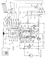
- FIG. 1 shows a schematic representation of an electrohydraulic control device 10 with a hydraulic control block 11, which controls the pressure medium supply from a pump 12 to a hydraulic cylinder 13 of a forming machine, in this exemplary embodiment a press.
- a forming tool of the press is held on the piston rod of the cylinder 13, designated 14.
- the chambers of the cylinder 13 are designated by the reference numerals 15 (for the bottom-side chamber) and 16 (for the rod-side chamber).
- the piston of the cylinder 13 is provided with the reference number 17.
- Channels for hydraulic pressure medium are arranged in the control block 11. On the control block 11, two valves 18 and 19 are held, which control the flow of the pressure medium.
- the valves 18 and 19 can be actuated by electrical signals y 18a , y 18b and y 19a , which are fed to two solenoid coils 18a and 18b of the valve 18 and a solenoid coil 19a of the valve 19, respectively.
- the valves 18 and 19 can be both directly controlled valves and pilot operated valves.
- three pressure limiting valves 20, 21 and 22 and a check valve 23 are held on the control block 11.
- the control block 11 has four hydraulic connections, which are labeled P, T, A and B.
- the pressure medium is supplied to the control block 11 via the port P.
- the ports A and B of the control block 11 are connected to the chambers 16 and 15 of the cylinder 13, respectively. If the forming tool is actuated by a plurality of cylinders, the corresponding chambers of the further cylinders are likewise connected to the connections A and B of the control block 11.
- the control block 11 is connected to a tank 25 via the connection T.
- An electrical circuit arrangement 30, which is held firmly on the hydraulic control block 11, forms with the latter. a structural unit.
- the circuit arrangement 30 is provided with interfaces 31e, 31i, 32 and 33 for electrical connecting lines. A number of electrical input signals are supplied to the circuit arrangement 30 via the interfaces 31e and 31i. Via the interface 32, which is permanently wired to the magnetic coils 18a, 18b and 19a by means of electrical lines 18a *, 18b * and 19a *, the circuit arrangement 30 outputs the electrical actuating signals y 18a , y 18b , y 19a for the valves 18 and 19 out.
- the circuit arrangement 30 communicates with a higher-level sequence control 35 via the interface 33 and a control bus 34.
- the safety-relevant sensors in FIG. 1 is provided with mechanically coded plug connections 41 which are connected within the circuit arrangement 30 by electrical lines 41 * to the interface 31e , A number of external sensors are connected to the plug connections 41 via correspondingly coded mating plugs.
- the external sensors are sensors that are considered safety-relevant in accordance with the regulations that apply to metal forming machines, and sensors that are not considered safety-relevant in this context.
- the safety-relevant sensors in FIG. 1 also include security doors (not shown for reasons of clarity) which secure access to a hazardous area.
- the two-hand press actuation 43 only allows the forming tool held on the piston rod 14 to be lowered if the operator actuates the two-hand press actuation 43 with both hands. Like the protective grille 45, the two-hand press actuation 43 is intended to prevent the operator from reaching into the press during the movement of the forming tool.
- the emergency stop switch 44 When the emergency stop switch 44 is actuated, the forming tool should be moved into a safe position as quickly as possible and should remain securely held there. 1 and 2, a displacement sensor 48 and two limit switches 49 and 50 are shown as non-safety-relevant sensors.
- the displacement sensor 48 supplies an electrical signal which is a measure of the position of the piston 17 and thus also of the forming tool held on the piston rod 14.
- the limit switches 49 and 50 emit an electrical switching signal when the piston rod 14 reaches a predeterminable position. Both limit switches can be moved along the direction of movement of the piston rod 14 and can be set to the desired position values.
- the limit switch 49 is assigned to an upper position and the limit switch 50 to a lower position.
- the reference symbols of the connecting lines leading from the external sensors 43 to 45 and 48 to 50 to the plug connections 41 are formed from the reference symbol of the respective sensor and a "*" supplementing this reference symbol.
- the reference symbols of the electrical signals of the sensors are formed from the letter "x" and an index consisting of the reference symbols of the respective sensor. So z. B. the leading from the press two-hand control 43 to the plug connections 41 with 43 * and the electrical signal of the press two-hand control is designated with x 43 .
- the hydraulic control block 11 is constructed so that it Requirements of the regulations for hydraulic safety equivalent.
- the pressure relief valve 20 limits in the usual way Way the outlet pressure of the pump 12.
- the pressure relief valve 21 limits the pressure in the chamber 16 of the cylinder 13.
- the pressure relief valve 22 ensures connection with the check valve 23 so that the piston 17th only moves down when the pressure in chamber 16 - due to a corresponding pressurization of the chamber 15 - exceeds a predeterminable value.
- the response pressure the pressure relief valve 22 is dimensioned so that the Dead weight of the piston 17, the piston rod 14 and the this held forming tool does not yet sink of the forming tool.
- the piston 17 only moves then down when the chamber 15 is additionally pressurized is applied. This is only the case if that Valve 19 is switched to the working position and the valve 18 is actuated in the direction in which the chamber 15 Pressure medium is supplied. To the piston 17 upwards move, the valve 19 must be switched to its working position be and the valve 18 operated in the direction in which is a pressure medium supply to the chamber 16, wherein at the same time pressure medium from chamber 15 via valve 18 is displaced to the tank 25.
- the valve 18 is provided with a displacement sensor 55, which emits an electrical signal x 55 , which is a measure of the position of the control slide of the valve 18.
- the output of the displacement sensor 55 is hard-wired to the interface 31i via an electrical line 55 *.
- the valve 18 is provided with a positive overlap. Due to this measure, a pressure medium flow only takes place when the control slide has covered a minimum distance. This makes it possible to detect the direction of movement of the control slide when the valve 18 is actuated by the displacement sensor 55, without pressure medium already flowing through the valve 18. If the control slide moves in the desired direction, the valve 18 is actuated further. In contrast, the control slide of the valve 18, z. B. due to a fault, in the wrong direction, the circuit arrangement 30 stops the control of the valve 18.
- the valve 19 is provided with a displacement sensor 57 which emits an electrical signal x 57 .
- the output signal x 57 of the displacement sensor 57 is a measure of the position of the control slide of the valve 19.
- the output of the displacement sensor 57 is hard-wired to the interface 31i of the circuit arrangement 30 via an electrical line 57 *.
- the linking of the electrical signals to that of the circuit arrangement 30 from the control block 11 via the interface 31i and from external sensors 43 to 45 and 48 to 50 supplied via the plug connections 41 and the interface 31e are done in digital form by a microprocessor 60.
- the microprocessor 60 is together with memory chips 61 and other electronic not shown Blocks arranged on a circuit board 62.
- the Signal linking takes place according to an algorithm that works accordingly the structure and purpose of the control block 11 is formed. Details of digital signal linking by the microprocessor 60 are as follows not described, since such signal links are basically known are.
- control block 11 is certified for hydraulic safety and that the electrical connections 18a *, 18b *, 19a *, 55 *, 57 * between the electrical held on the control block 11 Components and the interfaces 31i and 32 of the circuit arrangement 30 as well as the electrical connections 41 * between the interface 31e and the mechanically coded Plug connections 41 are hard-wired at the factory.
- This Measures allow the control block 11 and the Circuit arrangement 30 existing control device 10 together with the algorithm for signal linking in the To certify circuit arrangement 30. So there is one Type-tested device for controlling a hydraulic Cylinders of a metal forming machine that are complete assembled and tested. The mix-up safe Connections prevent errors when connecting the external sensors.
- the circuit arrangement 30 contains the for PLC functionality required for the respective application. In addition, all are in the circuit arrangement 30 safety components integrated. I.e. the Start and stop functions in the safety-related parts the control of the forming machine are hardwired and self-monitoring.
- the control device thus corresponds 10 the requirements for safety-related Parts of control and monitoring devices for hydraulic Forming machines.
- the bus 34 is used for communication Circuit arrangement 30 with the higher-level sequence control 35.
- the sequence control 35 is used to specify setpoints and parameters, to release processing steps and for visualization. Because there are no security-related issues Data transmitted over bus 34 is for data transmission between the sequencer 35 and the circuit arrangement 30 of the control unit 10 - unlike one central safety control - no safety bus required.
- FIG. 2 shows a partial area of that shown in FIG. 1 Control device.
- Another bus 66 serves as the AS-Interface bus EN 50295 is formed.
- AS-Interface bus EN 50295 is formed.
- security-relevant Sensors such as sensors 43 to 45
- sensors 48 to 50 are connected to the AS-Interface bus.
- the connection of the Sensors on the bus 66 take place via interfaces 43s, 44s, 45s, 48s, 49s and 50s.
- an interface serves the bus 66 to the circuit arrangement 30 68, which has an internal bus section 69 the interface 31e is wired.
- a safety monitor via a further interface 70 72 connected.
- the safety monitor 72 detects the safety-relevant ones Signals, d. H. the signals of the safety-relevant Sensors 43 to 45, and leads them to the Interface 31e via a line 73 to.
- the not security relevant Signals, d. H. the signals of the non-safety-relevant Sensors 48 to 50 are the interface 31e fed directly via the bus section 69.
- the configuration of the control device 10 only requires the bus 66 to be connected to the interface 68.
- the trapezoidal cross-section ensures the AS-Interface bus system of the two-wire connecting the individual interfaces Cable for a connection of the external sensors to the interface 68.
- the safety-relevant Safety monitor 72 evaluating signals arranged within the circuit arrangement 30 and with the other components hard-wired. The security monitor 72 and its wiring can therefore be included in the safety test the control device 10 are included.
- the electrical signals from the external To supply sensors to the electrical circuit arrangement 30, consists of connecting the safety-relevant external sensors 43 to 45 (as in FIG. 1) via mechanically coded plug connections with the circuit arrangement 30 to connect and the non-security external sensors 48 to 50 (as in FIG. 2) via a Data bus, e.g. B. an AS-Interface data bus with the electrical Circuit arrangement 30 to connect.
- a Data bus e.g. B. an AS-Interface data bus with the electrical Circuit arrangement 30 to connect.
- the safety monitor 72 shown in FIG. 2 is not required, since only the signals of the safety-relevant external sensors are transmitted.
- the signals of the external safety-relevant sensors but also the signals of the external non-safety-relevant sensors of the electrical circuit arrangement 30 via confusion-proof Connections fed.
Applications Claiming Priority (2)
| Application Number | Priority Date | Filing Date | Title |
|---|---|---|---|
| DE10150768A DE10150768A1 (de) | 2001-10-13 | 2001-10-13 | Einrichtung zur Steuerung eines hydraulischen Zylinders |
| DE10150768 | 2001-10-13 |
Publications (3)
| Publication Number | Publication Date |
|---|---|
| EP1302256A2 true EP1302256A2 (fr) | 2003-04-16 |
| EP1302256A3 EP1302256A3 (fr) | 2003-06-04 |
| EP1302256B1 EP1302256B1 (fr) | 2004-08-25 |
Family
ID=7702522
Family Applications (1)
| Application Number | Title | Priority Date | Filing Date |
|---|---|---|---|
| EP02022661A Expired - Lifetime EP1302256B1 (fr) | 2001-10-13 | 2002-10-10 | Dispositif de contrôle d'un vérin hydraulique |
Country Status (4)
| Country | Link |
|---|---|
| EP (1) | EP1302256B1 (fr) |
| AT (1) | ATE274384T1 (fr) |
| DE (2) | DE10150768A1 (fr) |
| ES (1) | ES2223023T3 (fr) |
Cited By (6)
| Publication number | Priority date | Publication date | Assignee | Title |
|---|---|---|---|---|
| WO2005119382A1 (fr) * | 2004-06-01 | 2005-12-15 | Siemens Aktiengesellschaft | Commande programmable utilisee en technique d'automatisation |
| EP1995601A1 (fr) * | 2007-05-24 | 2008-11-26 | Maprotec Société Anonyme | Répartiteur pour des capteurs détecteurs de proximité |
| DE102009020643A1 (de) | 2009-05-09 | 2010-11-11 | Robert Bosch Gmbh | Ventilanordnung mit integrierter Sicherheitsfunktion |
| CN102303421A (zh) * | 2011-09-20 | 2012-01-04 | 天津市天锻压力机有限公司 | 液压机运行速度的控制系统及控制方法 |
| US10400905B2 (en) | 2015-09-17 | 2019-09-03 | Robert Bosch Gmbh | Control device for controlling a valve arrangement and method for controlling a safety arrangement comprising said control device and said valve arrangement |
| CN110978611A (zh) * | 2020-03-03 | 2020-04-10 | 湖南华星能源仪器有限公司 | 一种适用生物燃料工业分析的控制系统 |
Families Citing this family (2)
| Publication number | Priority date | Publication date | Assignee | Title |
|---|---|---|---|---|
| DE10340506B4 (de) * | 2003-09-03 | 2006-05-04 | Sauer-Danfoss Aps | Ventilanordnung zur Steuerung eines Hydraulikantriebes |
| DE10340504B4 (de) * | 2003-09-03 | 2006-08-24 | Sauer-Danfoss Aps | Ventilanordnung zur Steuerung eines Hydraulikantriebs |
Citations (3)
| Publication number | Priority date | Publication date | Assignee | Title |
|---|---|---|---|---|
| DE3440849A1 (de) * | 1984-11-08 | 1986-05-07 | Mannesmann Rexroth GmbH, 8770 Lohr | Hydraulische steuervorrichtung |
| US5027631A (en) * | 1987-12-04 | 1991-07-02 | Amada Company, Limited | Method and device for controlling the stroke of a press machine |
| DE19515640A1 (de) * | 1995-04-28 | 1996-10-31 | Rexroth Mannesmann Gmbh | Schaltungsanordnung für die elektrische Ansteuerung eines Fluidik-Ventils |
Family Cites Families (9)
| Publication number | Priority date | Publication date | Assignee | Title |
|---|---|---|---|---|
| DE2319626C2 (de) * | 1973-04-18 | 1984-04-26 | Maschinenfabrik Müller-Weingarten AG, 7987 Weingarten | Elektrische Sicherheitssteuerung für Pressen, Stanzen und dergleichen |
| DE2649793C2 (de) * | 1976-10-29 | 1983-09-08 | Hartmann & Lämmle GmbH & Co KG, 7255 Rutesheim | Sicherheitssteuerung für eine hydraulisch betätigbare Presse |
| DD204526A1 (de) * | 1982-03-12 | 1983-11-30 | Dietrich Richter | Schaltungsanordnung zur fehlersicheren ueberwachung einer speicherprogrammierbaren pressensicherheitssteuerung |
| DD249166A3 (de) * | 1985-04-09 | 1987-09-02 | Werkzeugmaschinenfabrik Zeulen | Sicherheitsschaltung fuer pressen |
| DE3732717A1 (de) * | 1987-09-29 | 1989-04-06 | Smg Sueddeutsche Maschinenbau | Sicherheitssteuerung fuer hydraulische pressen |
| DD274072A1 (de) * | 1988-07-11 | 1989-12-06 | Werkzeugmaschinenfabrik Zeulen | Schaltungsanordnung fuer eine pressensicherheitssteuerung |
| IT1250831B (it) * | 1991-07-31 | 1995-04-21 | Fiat Auto Spa | Sistema per il controllo in sicurezza intrinseca della sterzatura delle ruote posteriori di un autoveicolo. |
| DE29901062U1 (de) * | 1999-01-22 | 2000-06-29 | Netz Horst | Grundverdrahtungssystem für Elektroverteilung |
| DE19952023C2 (de) * | 1999-10-28 | 2003-05-15 | Grote & Hartmann | Steckverbinderkupplung |
-
2001
- 2001-10-13 DE DE10150768A patent/DE10150768A1/de not_active Withdrawn
-
2002
- 2002-10-10 DE DE50200890T patent/DE50200890D1/de not_active Expired - Lifetime
- 2002-10-10 EP EP02022661A patent/EP1302256B1/fr not_active Expired - Lifetime
- 2002-10-10 AT AT02022661T patent/ATE274384T1/de not_active IP Right Cessation
- 2002-10-10 ES ES02022661T patent/ES2223023T3/es not_active Expired - Lifetime
Patent Citations (3)
| Publication number | Priority date | Publication date | Assignee | Title |
|---|---|---|---|---|
| DE3440849A1 (de) * | 1984-11-08 | 1986-05-07 | Mannesmann Rexroth GmbH, 8770 Lohr | Hydraulische steuervorrichtung |
| US5027631A (en) * | 1987-12-04 | 1991-07-02 | Amada Company, Limited | Method and device for controlling the stroke of a press machine |
| DE19515640A1 (de) * | 1995-04-28 | 1996-10-31 | Rexroth Mannesmann Gmbh | Schaltungsanordnung für die elektrische Ansteuerung eines Fluidik-Ventils |
Cited By (7)
| Publication number | Priority date | Publication date | Assignee | Title |
|---|---|---|---|---|
| WO2005119382A1 (fr) * | 2004-06-01 | 2005-12-15 | Siemens Aktiengesellschaft | Commande programmable utilisee en technique d'automatisation |
| EP1995601A1 (fr) * | 2007-05-24 | 2008-11-26 | Maprotec Société Anonyme | Répartiteur pour des capteurs détecteurs de proximité |
| FR2916536A1 (fr) * | 2007-05-24 | 2008-11-28 | Maprotec Sa | Repartiteur pour des capteurs detecteurs de proximite. |
| DE102009020643A1 (de) | 2009-05-09 | 2010-11-11 | Robert Bosch Gmbh | Ventilanordnung mit integrierter Sicherheitsfunktion |
| CN102303421A (zh) * | 2011-09-20 | 2012-01-04 | 天津市天锻压力机有限公司 | 液压机运行速度的控制系统及控制方法 |
| US10400905B2 (en) | 2015-09-17 | 2019-09-03 | Robert Bosch Gmbh | Control device for controlling a valve arrangement and method for controlling a safety arrangement comprising said control device and said valve arrangement |
| CN110978611A (zh) * | 2020-03-03 | 2020-04-10 | 湖南华星能源仪器有限公司 | 一种适用生物燃料工业分析的控制系统 |
Also Published As
| Publication number | Publication date |
|---|---|
| EP1302256B1 (fr) | 2004-08-25 |
| DE10150768A1 (de) | 2003-04-17 |
| ES2223023T3 (es) | 2005-02-16 |
| EP1302256A3 (fr) | 2003-06-04 |
| ATE274384T1 (de) | 2004-09-15 |
| DE50200890D1 (de) | 2004-09-30 |
Similar Documents
| Publication | Publication Date | Title |
|---|---|---|
| EP2622229B1 (fr) | Appareil d'entretien à air comprimé et dispositif de commande d'utilisateur équipé de ce dernier | |
| DE102004028437B3 (de) | Ventilanordnung | |
| EP1589386B1 (fr) | Système de commande de processus | |
| EP2220377B1 (fr) | Mécanisme à soupape | |
| EP1264110B1 (fr) | Dispositif pour commander un actionneur hydraulique | |
| EP1266147B1 (fr) | Systeme fluidique a fonction de securite | |
| DE102004052602B4 (de) | Ventilanordnung | |
| EP1302256B1 (fr) | Dispositif de contrôle d'un vérin hydraulique | |
| EP2246756B1 (fr) | Procédé et appareil de commande destinés à commander un composant d'automatisation industriel lié à la sécurité | |
| EP1969435B1 (fr) | Dispositif pour commander au moins une machine | |
| DE102016106616B4 (de) | Elektrohydraulischer Steuerkreis für einen Großmanipulator | |
| WO2007096126A1 (fr) | Concept de sécurité pour un dispositif de positionnement à engrenage | |
| EP2154587B1 (fr) | Système de positionnement d'un actionneur | |
| EP2835699B1 (fr) | Dispositif et procédé de configuration et/ou de programmation d'un contrôleur de sécurité | |
| DE102010016492A1 (de) | Werkzeugzustandsüberwachung | |
| EP2805063B1 (fr) | Procédé de configuration d'un module de commande fluidique, produit logiciel informatique et système fluidique | |
| EP1846681B1 (fr) | Dispositif pour commander le mouvement de commutation d'une soupape | |
| EP1780422B1 (fr) | Système modulaire permettant un libre choix pour le contrôle d'éléments hydrauliques | |
| DE102012005224A1 (de) | Fluidsystem und Verfahren zum Betreiben eines Fluidsystems | |
| DE4232234C1 (de) | Vorrichtung zur Einstellung und Überwachung des Spanndrucks eines kraftbetätigten Spannfutters | |
| DE10351105B4 (de) | Elektrische Schaltunganordnung zur Steuerung der Schaltbewegung von Ventilen | |
| EP0884486A1 (fr) | Dispositif de serrage électrohydraulique | |
| EP2916182A1 (fr) | Module de commande de sécurité et dispositif de commande pour une machine de traitement à entraînement fluidique | |
| DE102014226617A1 (de) | Antriebsregelvorrichtung für einen elektro-hydraulischen Antrieb | |
| DE4432237A1 (de) | Steuerung für mobile Arbeitsmaschinen |
Legal Events
| Date | Code | Title | Description |
|---|---|---|---|
| PUAI | Public reference made under article 153(3) epc to a published international application that has entered the european phase |
Free format text: ORIGINAL CODE: 0009012 |
|
| AK | Designated contracting states |
Designated state(s): AT BE BG CH CY CZ DE DK EE ES FI FR GB GR IE IT LI LU MC NL PT SE SK TR |
|
| AX | Request for extension of the european patent |
Extension state: AL LT LV MK RO SI |
|
| PUAL | Search report despatched |
Free format text: ORIGINAL CODE: 0009013 |
|
| AK | Designated contracting states |
Designated state(s): AT BE BG CH CY CZ DE DK EE ES FI FR GB GR IE IT LI LU MC NL PT SE SK TR |
|
| AX | Request for extension of the european patent |
Extension state: AL LT LV MK RO SI |
|
| 17P | Request for examination filed |
Effective date: 20031203 |
|
| AKX | Designation fees paid |
Designated state(s): AT BE BG CH CY CZ DE DK EE ES FI FR GB GR IE IT LI LU MC NL PT SE SK TR |
|
| GRAP | Despatch of communication of intention to grant a patent |
Free format text: ORIGINAL CODE: EPIDOSNIGR1 |
|
| GRAS | Grant fee paid |
Free format text: ORIGINAL CODE: EPIDOSNIGR3 |
|
| GRAA | (expected) grant |
Free format text: ORIGINAL CODE: 0009210 |
|
| AK | Designated contracting states |
Kind code of ref document: B1 Designated state(s): AT BE BG CH CY CZ DE DK EE ES FI FR GB GR IE IT LI LU MC NL PT SE SK TR |
|
| PG25 | Lapsed in a contracting state [announced via postgrant information from national office to epo] |
Ref country code: NL Free format text: LAPSE BECAUSE OF FAILURE TO SUBMIT A TRANSLATION OF THE DESCRIPTION OR TO PAY THE FEE WITHIN THE PRESCRIBED TIME-LIMIT Effective date: 20040825 Ref country code: FI Free format text: LAPSE BECAUSE OF FAILURE TO SUBMIT A TRANSLATION OF THE DESCRIPTION OR TO PAY THE FEE WITHIN THE PRESCRIBED TIME-LIMIT Effective date: 20040825 Ref country code: BG Free format text: LAPSE BECAUSE OF FAILURE TO SUBMIT A TRANSLATION OF THE DESCRIPTION OR TO PAY THE FEE WITHIN THE PRESCRIBED TIME-LIMIT Effective date: 20040825 Ref country code: EE Free format text: LAPSE BECAUSE OF FAILURE TO SUBMIT A TRANSLATION OF THE DESCRIPTION OR TO PAY THE FEE WITHIN THE PRESCRIBED TIME-LIMIT Effective date: 20040825 Ref country code: GB Free format text: LAPSE BECAUSE OF FAILURE TO SUBMIT A TRANSLATION OF THE DESCRIPTION OR TO PAY THE FEE WITHIN THE PRESCRIBED TIME-LIMIT Effective date: 20040825 Ref country code: CY Free format text: LAPSE BECAUSE OF FAILURE TO SUBMIT A TRANSLATION OF THE DESCRIPTION OR TO PAY THE FEE WITHIN THE PRESCRIBED TIME-LIMIT Effective date: 20040825 Ref country code: IE Free format text: LAPSE BECAUSE OF FAILURE TO SUBMIT A TRANSLATION OF THE DESCRIPTION OR TO PAY THE FEE WITHIN THE PRESCRIBED TIME-LIMIT Effective date: 20040825 Ref country code: SK Free format text: LAPSE BECAUSE OF FAILURE TO SUBMIT A TRANSLATION OF THE DESCRIPTION OR TO PAY THE FEE WITHIN THE PRESCRIBED TIME-LIMIT Effective date: 20040825 Ref country code: TR Free format text: LAPSE BECAUSE OF FAILURE TO SUBMIT A TRANSLATION OF THE DESCRIPTION OR TO PAY THE FEE WITHIN THE PRESCRIBED TIME-LIMIT Effective date: 20040825 Ref country code: FR Free format text: LAPSE BECAUSE OF FAILURE TO SUBMIT A TRANSLATION OF THE DESCRIPTION OR TO PAY THE FEE WITHIN THE PRESCRIBED TIME-LIMIT Effective date: 20040825 |
|
| REG | Reference to a national code |
Ref country code: GB Ref legal event code: FG4D Free format text: NOT ENGLISH |
|
| REG | Reference to a national code |
Ref country code: CH Ref legal event code: EP |
|
| REG | Reference to a national code |
Ref country code: IE Ref legal event code: FG4D Free format text: GERMAN |
|
| REF | Corresponds to: |
Ref document number: 50200890 Country of ref document: DE Date of ref document: 20040930 Kind code of ref document: P |
|
| PG25 | Lapsed in a contracting state [announced via postgrant information from national office to epo] |
Ref country code: AT Free format text: LAPSE BECAUSE OF NON-PAYMENT OF DUE FEES Effective date: 20041010 Ref country code: LU Free format text: LAPSE BECAUSE OF NON-PAYMENT OF DUE FEES Effective date: 20041010 |
|
| PG25 | Lapsed in a contracting state [announced via postgrant information from national office to epo] |
Ref country code: BE Free format text: LAPSE BECAUSE OF NON-PAYMENT OF DUE FEES Effective date: 20041031 Ref country code: MC Free format text: LAPSE BECAUSE OF NON-PAYMENT OF DUE FEES Effective date: 20041031 |
|
| PG25 | Lapsed in a contracting state [announced via postgrant information from national office to epo] |
Ref country code: DK Free format text: LAPSE BECAUSE OF FAILURE TO SUBMIT A TRANSLATION OF THE DESCRIPTION OR TO PAY THE FEE WITHIN THE PRESCRIBED TIME-LIMIT Effective date: 20041125 Ref country code: GR Free format text: LAPSE BECAUSE OF FAILURE TO SUBMIT A TRANSLATION OF THE DESCRIPTION OR TO PAY THE FEE WITHIN THE PRESCRIBED TIME-LIMIT Effective date: 20041125 |
|
| REG | Reference to a national code |
Ref country code: SE Ref legal event code: TRGR |
|
| REG | Reference to a national code |
Ref country code: ES Ref legal event code: FG2A Ref document number: 2223023 Country of ref document: ES Kind code of ref document: T3 |
|
| LTIE | Lt: invalidation of european patent or patent extension |
Effective date: 20040825 |
|
| NLV1 | Nl: lapsed or annulled due to failure to fulfill the requirements of art. 29p and 29m of the patents act | ||
| GBV | Gb: ep patent (uk) treated as always having been void in accordance with gb section 77(7)/1977 [no translation filed] |
Effective date: 20040825 |
|
| REG | Reference to a national code |
Ref country code: IE Ref legal event code: FD4D |
|
| BERE | Be: lapsed |
Owner name: BOSCH REXROTH A.G. Effective date: 20041031 |
|
| PLBE | No opposition filed within time limit |
Free format text: ORIGINAL CODE: 0009261 |
|
| STAA | Information on the status of an ep patent application or granted ep patent |
Free format text: STATUS: NO OPPOSITION FILED WITHIN TIME LIMIT |
|
| 26N | No opposition filed |
Effective date: 20050526 |
|
| EN | Fr: translation not filed | ||
| PG25 | Lapsed in a contracting state [announced via postgrant information from national office to epo] |
Ref country code: CH Free format text: LAPSE BECAUSE OF NON-PAYMENT OF DUE FEES Effective date: 20061031 Ref country code: LI Free format text: LAPSE BECAUSE OF NON-PAYMENT OF DUE FEES Effective date: 20061031 |
|
| REG | Reference to a national code |
Ref country code: CH Ref legal event code: PL |
|
| BERE | Be: lapsed |
Owner name: *BOSCH REXROTH A.G. Effective date: 20041031 |
|
| PG25 | Lapsed in a contracting state [announced via postgrant information from national office to epo] |
Ref country code: PT Free format text: LAPSE BECAUSE OF NON-PAYMENT OF DUE FEES Effective date: 20050125 |
|
| PGFP | Annual fee paid to national office [announced via postgrant information from national office to epo] |
Ref country code: CZ Payment date: 20081001 Year of fee payment: 7 |
|
| PGFP | Annual fee paid to national office [announced via postgrant information from national office to epo] |
Ref country code: ES Payment date: 20081027 Year of fee payment: 7 |
|
| PGFP | Annual fee paid to national office [announced via postgrant information from national office to epo] |
Ref country code: SE Payment date: 20081027 Year of fee payment: 7 |
|
| EUG | Se: european patent has lapsed | ||
| PG25 | Lapsed in a contracting state [announced via postgrant information from national office to epo] |
Ref country code: CZ Free format text: LAPSE BECAUSE OF NON-PAYMENT OF DUE FEES Effective date: 20091010 |
|
| REG | Reference to a national code |
Ref country code: ES Ref legal event code: FD2A Effective date: 20110310 |
|
| PG25 | Lapsed in a contracting state [announced via postgrant information from national office to epo] |
Ref country code: SE Free format text: LAPSE BECAUSE OF NON-PAYMENT OF DUE FEES Effective date: 20091011 |
|
| PG25 | Lapsed in a contracting state [announced via postgrant information from national office to epo] |
Ref country code: ES Free format text: LAPSE BECAUSE OF NON-PAYMENT OF DUE FEES Effective date: 20110309 |
|
| PG25 | Lapsed in a contracting state [announced via postgrant information from national office to epo] |
Ref country code: ES Free format text: LAPSE BECAUSE OF NON-PAYMENT OF DUE FEES Effective date: 20091011 |
|
| PGFP | Annual fee paid to national office [announced via postgrant information from national office to epo] |
Ref country code: DE Payment date: 20151215 Year of fee payment: 14 Ref country code: IT Payment date: 20151026 Year of fee payment: 14 |
|
| REG | Reference to a national code |
Ref country code: DE Ref legal event code: R119 Ref document number: 50200890 Country of ref document: DE |
|
| PG25 | Lapsed in a contracting state [announced via postgrant information from national office to epo] |
Ref country code: DE Free format text: LAPSE BECAUSE OF NON-PAYMENT OF DUE FEES Effective date: 20170503 |
|
| PG25 | Lapsed in a contracting state [announced via postgrant information from national office to epo] |
Ref country code: IT Free format text: LAPSE BECAUSE OF NON-PAYMENT OF DUE FEES Effective date: 20161010 |